

Page 1
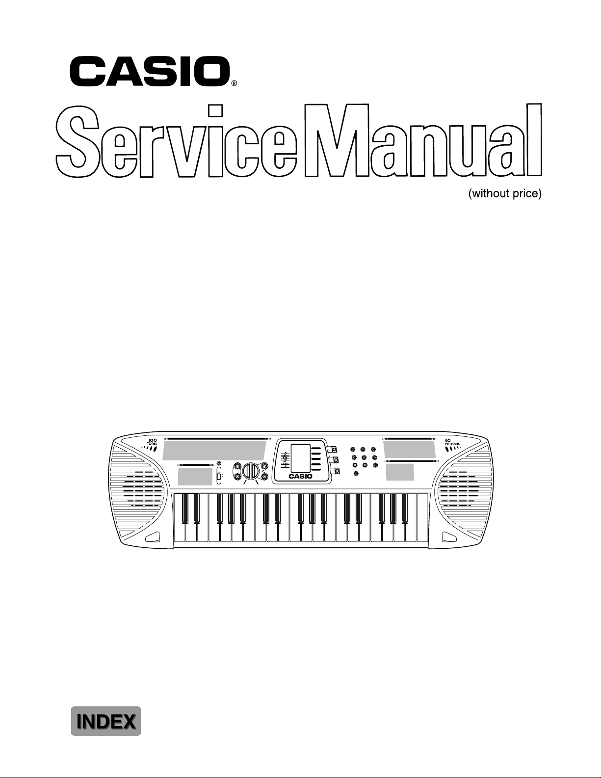
SA-65
POWER
ON
OFF
VOLUME
START/STOP MELODY OFF
MUSICAL INFORMATION SYSTEM
VOLUME
TEMPO
TONE
PATTERN
SONG BANK
TEMPO
78 9
TONE
45 6
PATTERN
1023
SONG
BANK
10 SONG BANK
SA-65
ELECTRONIC KEYBOARD
Page 2

CONTENTS
Specifications . . . . . . . . . . . . . . . . . . . . . . . . . . . . . . . . . . . . . . . . . . 1
Block Diagram . . . . . . . . . . . . . . . . . . . . . . . . . . . . . . . . . . . . . . . . . 2
Circuit Description . . . . . . . . . . . . . . . . . . . . . . . . . . . . . . . . . . . . . . . . 2
Waveforms . . . . . . . . . . . . . . . . . . . . . . . . . . . . . . . . . . . . . . . . . . 5
Printed Circuit Board . . . . . . . . . . . . . . . . . . . . . . . . . . . . . . . . . . . . . . 6
Schematic Diagrams . . . . . . . . . . . . . . . . . . . . . . . .. . . . . . . . . . . . . . 7
Exploded View . . . . . . . . . . . . . . . . . . . . . . . . . . . . . . . . . . . . . . . . . 9
Parts List . . . . . . . . . . . . . . . . . . . . . . . . . . . . . . . . . . . . . . . . . 11
Page 3
SPECIFICATIONS
GENERAL
Keyboard: 37 keys, 3 octaves (mini-size)
Polyphony: 4 notes maximum
Tones: 100
Patterns: 30 (RHYTHM, FREE SESSION, FUNNY)
Song band: 10 tunes; melody off
Tuning: Fixed; A4 = approx. 442 Hz
Speakers: Two; 8.0cm (output: 0.5 W + 0.5 W)
Input terminals: AC adaptor (7.5 V DC)
Power supply: Two-way
Five AA-size batteries
Battery Life: Approximately six hours on R6P (SUM-3) manganese batteries
AC Adaptor (AD-1)
Power consumption: 7.5 V 2.3 W
Dimensions (HWD): 74 × 650 × 211 mm
(2-15/16 × 25-5/8 × 8-5/16 inches)
Weight: Approximately 1.6 kg (3.53 lbs) (without batteries)
ELECTRICAL
Current drain with 7.5 V DC:
No sound output 33 mA ± 20 %
Maximum volume 230 mA ± 20 %
with keys G3, A#3, B3 and C4 pressed
in Car Horn tone, Volume: Maximum
Speaker output level 1060 mV ± 20 %
with key C2 pressed in Street Organ tone
Volume: Maximum
Minimum operating voltage: 5.5 V
Nomenclature of Keys
C#3
D#3 F#3 G#3 A#3 C#4 D#4 F#4 G#4 A#4 C#5 D#5 F#5 G#5 A#5
C3 D3 E3 F3 G3 A3 B3 C4 D4 E4 F4 G4 A4 B4 C5 D5 E5 F5 G5 A5 B5 C6
— 1 —
Page 4
BLOCK DIAGRAM
S1 ~ S14
S18 ~ S20
S31 ~ S46
Speaker
LCD
LCD Driver
KS0035
IC102
Amplifier
AN8053N
IC101
COM1, COM2
KO8 ~ KO11
Filter
Q101
VDD
CPU
MSM6387B-A28
LSI101
OUT
Oscillator
Q102, X101
KO0 ~ KO7
KI0 ~ KI7
Keyboard
Switches
CIRCUIT DESCRIPTION
Key Matrix
KI0 KI1 KI2 KI3 KI4 KI5 KI6 KI7
KO0 C3 C#3 D3 D#3 E3
KO1 F3 F#3 G3 G#3 A3 A#3 B3 C4
KO2 C#4 D4 D#4 E4 F4 F#4 G4 G#4
KO3 A4 A#4 B4 C5 C#5 D5 D#5 E5
KO4 F5 F#5 G5 G#5 A5 A#5 B5 C6
KO5 0 1 23 4
KO6 5 6789
KO7
Song
Bank Stop Down
Pattern Tone
Tempo
Volume
Start/ Volume
Up Off
Up Down
Melody
Tempo
— 2 —
Page 5
CPU (LSI101: MSM6387B-A28)
Containing a sound data ROM and a DAC (Digital to Analog Convertor), the CPU provides sound waveform
in accodance with the pressed key and the selected tone.
The following table shows the pin functions of LSI101.
Pin No. Terminal In/Out Function
1, 2 TEST1, TEST2
3 RESET In Power ON reset terminal. On: +5 V Off: 0 V
4 AVDD In +5 V source for the built-in DAC
5 OUT Out Sound waveform output
6 AGND In Ground (0 V) source for the built-in DAC
7 GND In Ground (0 V) source
8 COSI In 21.725 MHz clock pulse input
9 COSO
10 VDD In +5 V source
11 ~ 18 KI0 ~ KI7 In Input terminals from keys and switches
19 KO11 Out Display data output
20 KO10 Out Bit clock output
21 KO9 Out Chip enable signal for the LCD driver
22 KO8 Out Display blanking output
23 ~ 30 KO7 ~ KO0 Out Key scan signal outputs
—
—
Not used. Connected to ground.
Not used
LCD Driver (IC102 : KS0035)
The KS0035 is an LCD driver for a segment type LCD, and it can drive up to 53 segments.
The following table shows the pin functions of IC102.
Pin No. Terminal In/Out Function
1 ~ 14 S1 ~ S14 Out Segment output
15 ~ 17 S15 ~ S17
18 ~ 20 S18 ~ S20 Out Segment output
21 ~ 30 S21 ~ S29
31 ~ 47 S30 ~ S46 Out Segment output
36 S35
48 ~ 54 S47 ~ S53
55 OSC In Terminal for the internal clock generator
56 VDD In +5 V source
57 –INH In Display blanking input
58 VLCD In +5 V source for the internal driver
59 VSS In Ground (0 V) source
60 CE In Chip enable input
61 CLK In Bit clock input
62 DATA In Display data input
63, 64 COM1, COM2 Out Common out put
—
—
—
—
Not used
Not used
Not used
Not used
— 3 —
Page 6

Filter Block
Since the sound signal from the CPU is a stepped waveform, the filter block is added to smooth the waveform.
AVDD
Q101
2SC1740SR
R106
C106 R105
To power amp.
R104
AG
Amplifier/Voltage Regulator
(IC101: AN8053N)
The right figure shows the internal block of IC101.
From CPU
C108
AG
VCC NC CONT
16 9
15 14 13 12 11 10
POWER
1 3456782
SPO NC SP GND PC-1 PC-2 SPI SPM VREF
5 V
VREG NC NC NC PRE GND
5V REG
–
SP AMP
+
VREF
— 4 —
Page 7

1
2
3
WAVEFORMS
4
5
1 Main clock COSI
MSM6387B-A28 pin 8
6
7
2 Key scan signal KO0
MSM6387B-A28 pin 30
3 Key scan signal KO1
MSM6387B-A28 pin 29
8
4 Sound waveform
MSM6387B-A28 pin 5
5 Clock for LCD driver
KS0035 pin 55
Tone : Flute (No. 23)
Volume : 5 (Max.)
6 Chip enable signal KO9 (CE)
MSM 6387B-A28 pin 21
7 Clock for LCD driver KO10 (CLK)
MAM6387B-A28 pin 20
8 Display data KO11 (DATA)
MSM6387B-A28 pin 19
— 5 —
Page 8

Main PCB JCM548-MA1M
PRINTED CIRCUIT BOARD
8
5
7
6
4
1
3
2
— 6 —
Page 9

Main PCB JCM548-MA1M
1
4
3
2
5
6
7
8
SCHEMATIC DIAGRAMS
— 7 —
Page 10

Keyboard PCB JCM548-KY1M
— 8 —
Page 11

R-1
EXPLODED VIEW
3
10
5
10
8
4
11
14
1
2
9
13
12
6
15
R-2
7
— 9 —
Page 12

PARTS LIST
SA-65
Notes: This parts list does not include the cosmetic parts, which
parts are marked with item No. "R-X" in the exploded
view.
Contact our spare parts department if you need these
parts for refurbish.
1. Prices and specifications are subject to change without prior notice.
2. As for spare parts order and supply, refer to the
"GUIDEBOOK for Spare parts Supply", published
seperately.
3. The numbers in item column correspond to the same
numbers in drawing.
Page 13

Item Code No. Parts Name Specification Q R
Electrical Parts
1 6926 1200 PCB/ASSY (MA1M) M140578*1 1 B
LSI1 2012 5610 LSI/MC (CPU) MSM6387B-A28 1 A
IC101 2114 3269 IC/LINEAR (AMP) AN8053N 1 A
IC102 2114 5793 IC/MOS (LCD DRIVER) KS0035 1 A
Q101 2220 1409 TRANSISTOR 2SC1740SR-TP-T 1 B
Q102 2220 1387 TRANSISTOR 2SC1740SQ-TP-T 1 B
D101 2390 3018 DIODE 1T2 1 B
D102 2390 1323 DIODE RB100A-T32-T 1 B
D103 2310 7848 DIODE/ZENER RD4.3ESB2-T1-T 1 B
D104-D111 2390 1344 DIODE 1SS133T-77-T 8 B
LED101 2370 1383 LED TLR124(TPJ56,KT) 1 B
X101 2590 1897 OSCILLATOR/CERAMIC EFO-EN2175C4 1 B
J101 3501 3731 JACK/POWER HEC2305-01-250 1 A
2 6926 1230 PCB/ASSY (KY) M140580*1 1 B
D201-D237 2390 1344 DIODE 1SS133T-77-T 37 B
Mechanical Parts
3 6926 1000 PANEL/DISPLAY M340626-1 1 C
4 6921 5031 KNOB M311856A-1 1 B
5 6926 1290 KEY SET/BLACK M140541-1 1 A
6 6926 1280 KEY SET/WHITE M140540-1 1 A
7 6926 1210
8 6926 1300 RUBBER/INTERCONNECTOR M440442-2 2 B
9 3335 6569 LCD CG161-TS(A) 1 B
10 3831 1076 SPEAKER 300RB326 2 B
11 6926 1030 RUBBER/BUTTON M240595-1 1 B
12 6926 1020 RUBBER/BUTTON M240596-1 1 B
13 6926 1010
14 6909 5890 SWITCH/SLIDE KONB CSB-12D 1 B
15 6926 1040 RUBBER/CONTACT M240594-1 1 B
COVER/BATTERY
RUBBER/BUTTON
M340646*1 1 B
M240597-1 1 B
Notes: Q – Quantity per unit
R – Rank
— 11 —
Page 14

MA0600571A
8-11-10, Nishi-Shinjuku
Shinjuku-ku, Tokyo 160, Japan
Telephone: 03-3347-4926
 Loading...