

Page 1
RE-700(ZX-735)
INDEX
AUG. 1995
(without price)
R
Page 2

CONTENTS
OUTLINE ....................................................................................................................... 1
SPECIFICATIONS ......................................................................................................... 1
GENERAL GUIDE ......................................................................................................... 3
BATTERY REPLACEMENT.......................................................................................... 6
RESET OPERATION..................................................................................................... 7
TO SAVE THE DATA TO ANOTHER MACHINE.......................................................... 8
LSI PIN FUNCTION..................................................................................................... 10
DIAGNOSTIC PROGRAM........................................................................................... 12
ERROR MESSAGES................................................................................................... 13
SCHEMATIC DIAGRAM.............................................................................................. 14
EXPLODED VIEW ....................................................................................................... 15
PARTS LIST ............................................................................................................... .16
Page 3

OUTLINE
The unit checks spelling for you, and tells you the correct hyphenation of a word using a dictionary of
approximately 115,000 words. You can even use wild card characters to look up words. The unit has also the
digital diary functions such as Telephone Directory, Schedule, Memo, Secret, Timekeeping, Alarm and
Calculator mode.
SPECIFICATIONS
Spell Check/Hyphenation Mode
Automatic spell checking and hyphenation advice based on dictionary of approximately 115,000 words.
Telephone Directory Mode
Storage and recall of telephone directory data (name, telephone number, address, etc.). Each item can contain
up to 380 characters. Includes secret memory area and auto sort function.
Schedule Mode
Storage and recall of appointments for any date in the range of January 1901 through December 2099. Each
item can contain up to 372 characters. Includes secret memory area and auto sort function.
Data Memo Mode
Storage and recall of memos. Each item can contain up to 381 characters. Includes secret memory area and
auto sort function.
Timekeeping Mode
Average of accuracy ± 3 seconds per day under normal temperatures; year/month/date, hour/minute/seconds,
AM/PM, day of the week, daylight saving/standard time; full automatic calendar; 12/24 hour timekeeping
format
Alarm Mode
Daily Alarm (20-second electronic buzzer); Schedule Alarm (20-second electronic buzzer); Hourly Time Signal
(beeps every hour on the hour)
Calculator Mode
10-digit arithmetic calculations; constant calculations; memory calculations; 20-digit approximations; percentage calculations; square roots; sigh changes; function command signs.
Other functions
Contrast adjustment
— 1 —
Page 4
General
Display: Liquid crystal display
Memory Capacity: 27,014 bytes
Power Supply: Two lithium batteries (CR2032) ... Main and Back-up
Power Consumption: 0.05 W
Battery Life*: Main battery - approximately 200 hours (continuous display of main menu
screen)
approximately 1 year (1 hour use per day)
Back-up battery - approximately 2 years after the low main battery warning
appears on the display
* The batteries that come installed in this unit when you purchase it are for factory
test purposes, so they will probably not provide normal service life.
Auto Power Off: Approximately 6 minutes after last key operation
Ambient Temperature
Range: 0°C ~ 40°C (32°F ~ 104°F)
Dimensions: Folded: 12.4 (H) × 141 (W) × 82 (D) mm
(1/2" (H) × 5 1/2" (W) × 3 1/4" (D))
Unfolded: 10.6 (H) × 141 (W) × 159.5 (D) mm
(3/8" (H) × 5 1/2" (W) × 6 1/4" (D))
Weight: 105.7 g (3.7 oz) including batteries
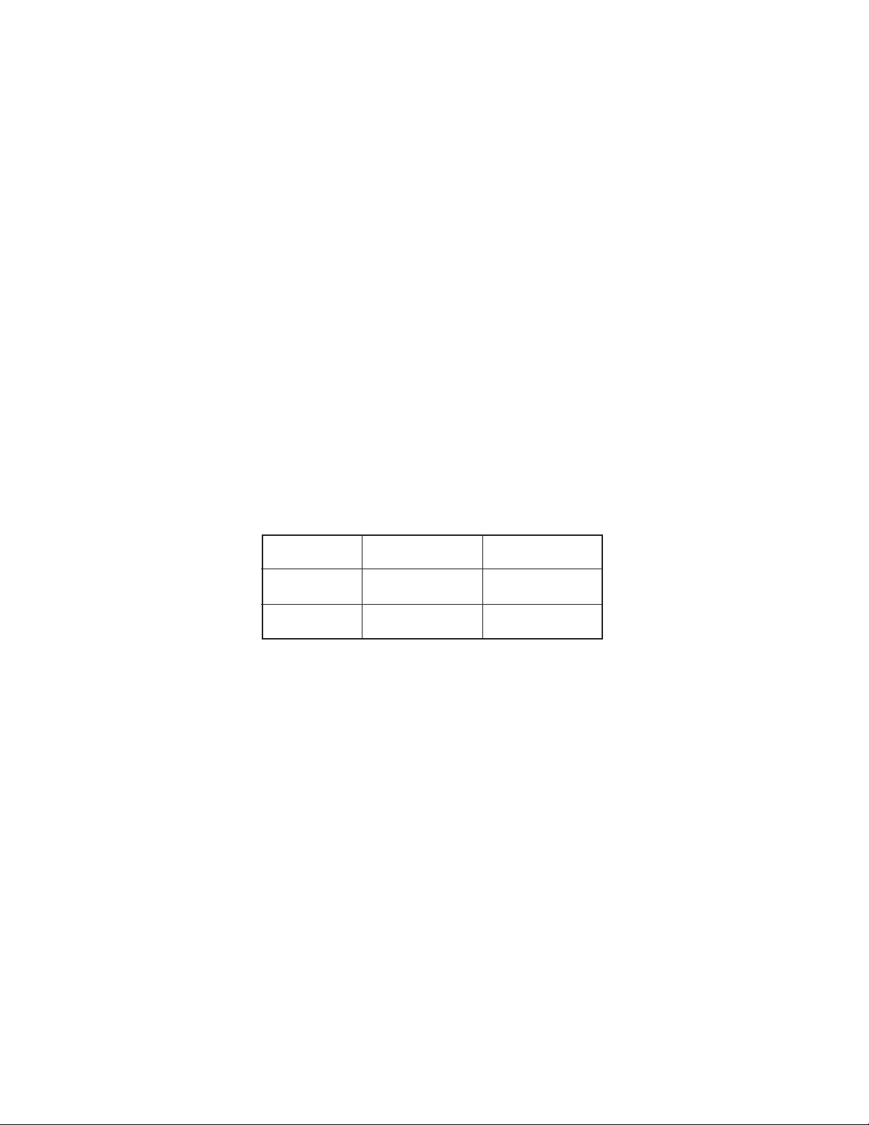
Current Consumption:
TYP [µA] Max [µA]
ON (MENU) 205.00 244.25
OFF — 8.25
— 2 —
Page 5
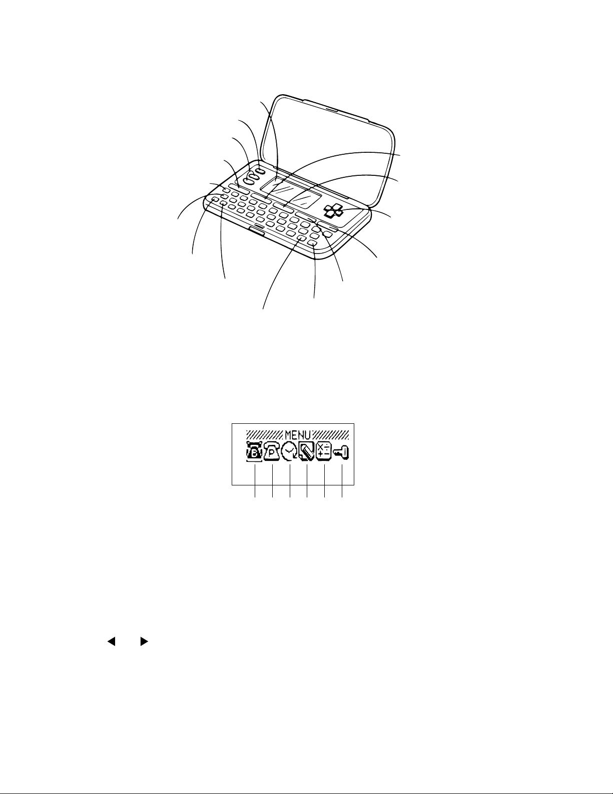
GENERAL GUIDE
Display
OFF Key
SEARCH Keys
SPELL/HYPHEN Key
CODE Key
C/CLR Key
AC/ON Key
SHIFT Key
SPACE/Return Key
Displaying the Main Menu Screen
Press MENU to display the main menu screen.
Main Menu Screen
MENU Key
TIME/ALARM Key
Cursor Keys
FUNCTION Key
ALPHA/NUMBER Key
EXE Key
123456
Menu Icons
1 Telephone Directory Business Mode
2 Telephone Directory Personal Mode
3 Schedule Mode
To change modes
1. Display the main menu screen.
2. The icon of the currently selected mode is highlighted on the display.
Use and to change the selected menu icon.
3. When the icon for the mode you want is selected (highlighted), press EXE.
• Press the TIME/ALARM key to enter the Timekeeping Mode and Alarm Mode. Each press of this key
switches between the two modes.
• Press the SPELL/HYPHEN key to enter the Spell Check Mode and Hyphenation Mode. Each press of
this key switches between the two modes.
— 3 —
4 Data Memo Mode
5 Calculator Mode
6 Secret Memory Area
Page 6
Using FUNCTION key
Use this key to access special functions and to perform other functions not marked on the keys. Use the
following sequence to access such functions.
1.Press FUNCTION.
2.Use and to move the highlighting to the function you want.
3.Press EXE to execute the function.
4.If another function menu appears, repeat step 2 and 3.
• To return to the previous display, press FUNCTION.
• To clear a displayed function menu, press AC.
To adjust the display contrast
1.Display the main menu screen.
2.To make the figures on the display darker, press . To make them lighter, press .
To switch the key input tone on and off
1.Press TIME/ALARM to enter the Alarm Mode.
2.Press FUNCTION.
3.Use to select “Sound”, and then press EXE.
4.Use to select “Key Tone”, and then use and to switch it on and off.
5.Press EXE to complete the setting operation.
About the “Check time!” display
When the message “Check time!” appears on the display, pressing any key displays the current time setting.
Check to make sure that the setting is correct before performing any other operation.
Low Battery Warning
A low battery warning protects against loss and corruption of data stored in memory due to weak battery power.
Replace the main battery immediately if the following display appears.
Main Battery
Getting Weak!
Replace it!
• Whenever the above display appears, only the OFF key is operational. Power switches off automatically
approximately 30 seconds after the low battery warning message appears.
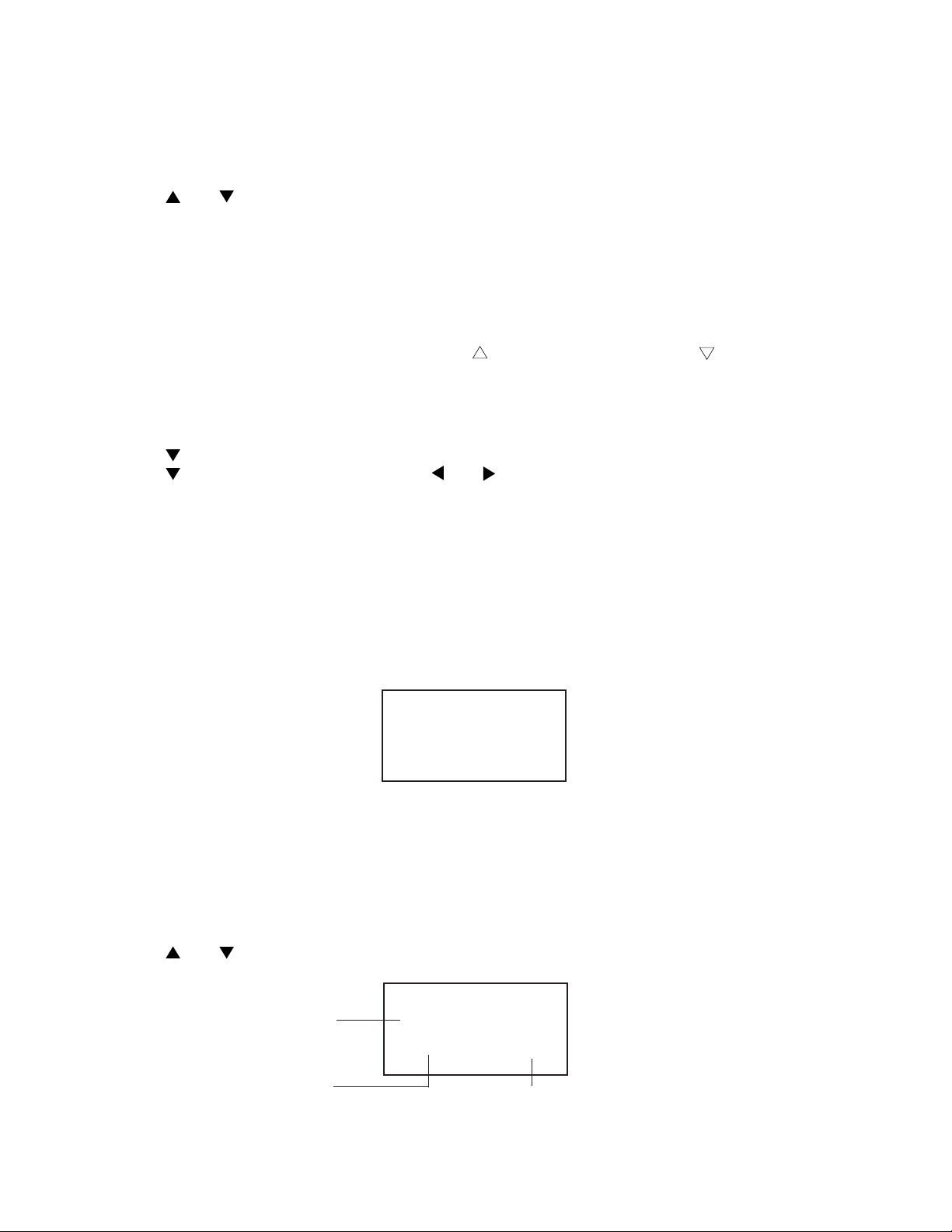
Memory Capacity Screen
To display the memory capacity
1.While the main menu is displayed, or any time you are in the Telephone Directory, Schedule, Data Memo
or Spell Check/Hyphenation Mode, press FUNCTION.
2.Use and to select “Memory Capacity” and then press EXE.
Memory Capacity
Remaining memory
(Unit: bytes)
Memory used
(Unit: bytes)
Free 25526
Used 1488 %
5
Memory used
— 4 —
Page 7

• The memory values shown on the previous page are the total for both the open memory area and the
secret memory area.
• Press AC to clear the memory capacity screen.
To display the number of items in each mode
1.While the main menu is displayed, press FUNCTION.
2.Use and to select "Number of Items" and press EXE.
Open Memory Area
Tel (Busi) : 27
Tel (Pers) : 50
Schedule : 1
Secret Memory Area
Tel (Busi) : 3
Tel (Pers) : 4
Schedule : 2
• If you perform the above procedure while in the open memory area, the number of items stored in the
open memory area only are displayed. To see the number of items in the secret memory area, you must
perform the above operation while accessing the secret memory area.
How memory capacity is calculated
You can store up to 27,014 bytes of data in memory. There is no limit on the amount of memory you can use
in each mode, but the total amount of data stored is 27,014 bytes. The following shows how many bytes the
data in each mode takes up. One character (each newline operation counts as a character also) takes up one
byte.
Mode Bytes per Data Item
Telephone Directory (name) + (telephone number) + (address, etc.) + 4
Schedule (description) + 12
Data Memo (memo name) + (memo contents) + 3
Examples:
Telephone Directory
When all items use 8 characters for the name, 10 characters for the phone number, and 20 characters
for the address, you can store approximately 640 items.
Schedule
When all items use 20 characters, you can store approximately 840 items.
Data Memo
When all items use 10 characters for the memo name and 10 characters for the memo content, you can
store approximately 1,170 items.
— 5 —
Page 8

BATTERY REPLACEMENT
Note that the main battery and the back-up battery should be replaced separately. If you remove both batteries
from the unit at the same time, all data stored in memory will be erased. Whenever you remove both batteries
from the unit, be sure to re-install the main battery first.
Important!
• Make sure that the positive (+) side of the batteries is always facing up (so you can see it) when you install
batteries into the unit.
• Replace the back-up battery at least once every two years.
To replace the main battery
1. Loosen the screw that holds the battery compartment cover of the unit in place and remove the battery
compartment cover.
2. Loosen the screw that secures the main battery holder in place and remove the battery holder.
3. Insert a thin, pointed non-metallic object into (A) and remove the old battery.
Back-up battery
Main battery
RESET
(A)
4. Wipe off the surfaces of a new battery with a dry, soft cloth and insert it into the unit making sure that its
positive (+) side is facing up (so you can see it).
5. Replace the battery holder and secure it in place with its screw.
6. Replace the battery compartment cover and secure it in place with its screw.
To replace the back-up battery
1. Loosen the screw that holds the battery compartment cover of the unit in place and remove the battery
compartment cover.
2. Remove the back-up battery sticker.
3. Loosen the screw that secures the back-up battery holder in place and remove the battery holder.
4. Insert a thin, pointed non-metallic object into (B) and remove the old battery.
(B)
5. Wipe off the surfaces of a new battery with a dry, soft cloth and insert it into the unit making sure that its
positive (+) side is facing up (so you can see it).
6. Replace the back-up battery holder and secure it in place with its screw.
7. Do not forget to replace the sticker.
8. Replace the battery compartment cover and secure it in place with its screw.
— 6 —
Page 9

RESET OPERATION
Two kinds of reset operation can be performed. The all-reset operation deletes all data in memory. The secret
reset operation deletes only your password and the data in the secret memory area.
Important!
Be sure to perform the all-reset operation after purchasing the RE-700.
To perform all-reset
1. Switch power off.
2. Press the RESET button with a thin, pointed object.
3. Use to select “Reset”, and press EXE.
4. Use to select “Yes”, and press EXE.
5. The main menu screen appears and all data is deleted.
RESET button
To perform secret reset
1. Switch power off.
2. Press the reset button with a thin, pointed object.
3. Use to select “Del Secret Data”, and press EXE.
4. Use to select “Yes”, and press EXE.
5. The message “Check time!” appears and all data in the secret memory area and the password are deleted.
• If you want to cancel the reset operation status immediately after you press the RESET button, select
“Exit”, and press EXE.
RESET
The following are the initial settings produced by the all-reset operation.
Built-in Clock: 12:00 AM (midnight), January 1, 1996
12/24-Hour Format: 12-hour
Alarm: OFF
Alarm Time: 12:00 AM
Alarm Time Signal: OFF
Key Input Tone: ON
Date Format: Month/Day/Year
— 7 —
Page 10

TO SAVE THE DATA TO ANOTHER MACHINE
It is commonly necessary to save all data stored in the customer's unit before repairing it. For this purpose,
you can transfer the data of the RE-700 unit to another unit using the following procedure.
(1)To reset the receiving unit
Please reset the unit used to receive the data from the customer's unit.
(2)To connect transmission unit with receiving unit
Please remove the covers of battery compartments from both the transmission unit and the receiving unit,
and connect one with another as shown in the figures below;
Batteries
UNIT-1
CP51
DP1
CP52
MA713
MA713
1K51K
CP50
TX
GND
RX
DP1
CP51
CP52
3
2
1
UNIT-2
CP50
CP51
DP1
CP52
CP50
MA713
MA713
DTC114YKT
TX
1K51K
GND
RX
DTC114YKT
— 8 —
SB-61 / SB-62
3
2
1
Page 11

(3)To do data transfer
y
y
Please switch both the units on, and make them enter the TEST mode. Thus, you may start to transfer all
data of customer's unit to the reception unit as shown in the following procedures.
CUSTOMER'S BACK-UP UNIT
NO OPERATION DISPLAY DISPLAY
Press the RESET button with a thin,
1
pointed object.
2
EXE
Exit
Del Secret Data
Reset
Reset OK!
YYeess/No
3
4
5
6
7
8
9
10
11
12
13
EXE
TIME/ALARM
FUNCTION
EXE
10 0 1 1 9 0 1
EXE
ON MENU
Short the pads DP1 and CP50 for 3
seconds.
EXE
1
1
2
MENU MENU
This is TEST
To Escape
Press AC KEY
1.Service Trans
2.TEST
AC.ESC
Service Trans
1.TRANS 2.RCV
AC.ESC
Now Sending!
To Stop
Press AC ke
MENU
JAN/ 1/ 1996 MON
12:00 00 am
Date Format
12/24 Hours
TTiimmee SSeet
01/01/1901
t
12:00 am
JAN/ 1/ 1901 TUE
12:00 00 am
This is TEST
To Escape
Press AC KEY
1.Service Trans
2.TEST
AC.ESC
Service Trans
1.TRANS 2.RCV
AC.ESC
Receive OK!
To Stop
Press AC ke
14 (Succeeded)
(Failed)
15
Return to the procedure No.1.
MENU MENU
Send Error! Receive Error!
— 9 —
Page 12

LSI PIN FUNCTION
y
y
)
1. CPU (HC3009-02-F1)
Pin No. Signal In/Out Function
1 DUMMY — Not used
2 ~ 9 IO0 ~ 7 In/Out Data bus
10 CS6B0 Out Chip enable signal for ROM
11 CS7B0 Out Chip enable signal for RAM
12 DUMMY — Not used
13 WEB0 Out Write enable signal for RAM
14 OEB0 Out Output enable signal for RAM and ROM
15 ~ 32 AO0 ~ 17 Out Address bus
33 IT0 In Reception data input
34 IT2 In Interrupt signal input
35, 37 DUMMY, TRANS — Not used
36 BUFON Out Power supply control for ROM
38 ~ 44 KI1 ~ 7 In Key input signal
45 K18 In Not used
46 ~ 54 KO1, KO5 ~ 12 Out Key scan signal
55 DUMMY — Not used
56 VREG3 Out Power supply for RAM/3 (V)
57 VLCD Out 5.9 [V]
58 ~ 61 VT1 ~ 4 — VT1: 1.0 [V]; VT2: 2.9 [V]
VT3: 2.0 [V]; VT4: 3.9 [V]
62, 63 VREG1, 4 — VREG1: 2.6[V]; VREG4: 5.0[V]
64 VDB In Low battery detection
VDB<4.4 [V] Lower battery message
65, 66 VD3, 4 — VD3: 4.7[V]; VD4: 1.6[V]
67, 68 VD1, 2 — VD1: 4.7[V]; VD2: 1.6[V]
69 SW1 In 2.6 [V]
While pushing the reset button: 0 [V]
70, 71 BZ1, 2 Out Buzzer terminal
72, 73 TS1, 2 — Test for manufacturer
74 VREG2 Out 2 [V]
75 VCC In Power supply / 3 [V]
76 DUMMY — Not used
77, 78 VSS In GND/0 [V]
79 ~ 83 V0 ~ 4 Out The voltage for LCD drive
OFF: 0 [V]
V0: 3.6(Min) ~ 5.8(Max) [V]
ON
V1: 2.9(Min) ~ 4.6(Max) [V]
V2: 2.1(Min) ~ 3.5(Max) [V]
V3: 1.4(Min) ~ 2.4(Max) [V]
V4: 0.7(Min) ~ 1.2(Max) [V]
84 VSSR In GND / 0 [V]
85 ~ 108 C1 ~ 24 Out Common signal displa
109, 110 S1, S2 — Not used
111 ~ 205 S3 ~ 96 Out Segment signal for displa
206 DUMMY — Not used
207, 208 XI, XO In/Out Clock terminal (DT-26S
209 DUMMY — Not used
210, 211 PO, PI In/Out Main clock terminal (3.45 MG)
212 DUMMY — Not used
213, 214 PORT2,3 — Interrupt port
215 ~ 217 PORT4 ~ 6 In/Out For data communication
218 PORT7 — Interrupt port
219 OPT2 — Not used
— 10 —
Page 13

Pin No. Signal In/Out Function
)
220 OPT3 Out Turn on signal for Photo Sensor
22 1 OPT4 In Communication data through Photo Sensor
22 2 OPT5 Ou t Turn on signal for LED (Infrared
2. RAM (LC3564QM-85)
Pin No. Signal In/Out Function
1 NC — No connect
2 ~ 10 A0 ~ 7, A12 In Address bus
11 ~ 13 I/O 0 ~ 2 In/Out Data bus
14 GND In GND / 0 [V]
15 ~ 19 I/O 3 ~ 7 In/Out Data bus
20 CE In Chip enable signal
2 1 A1 0 In Address bus
2 2 O E In Output enable signal
23 ~ 25 A8, 9, 11 In Address bus
26 CE2 In Chip enable signal
27 WE In Write enable signal
28 VCC In Power supply / 3 [V]
— 11 —
Page 14

DIAGNOSTIC PROGRAM
g
MODE OPERATION DISPLAY NOTES
Power ON
Entering TEST
mode.
ROM / RAM
check
RAM check
ROM check
Display check
ON MENU
Short the pads DP1 and CP50 for
3 seconds.
EXE
2
1
SPACE
EXE
2
EXE
EXE
MENU
This is TEST
To Escape
Press AC KEY
1.Service Trans
2.TEST
AC.ESC
1.RAM, ROM
3.KEY
5.FCC
2.DISP
4.RESET
AC.ESC
32K RAM OK!
ROM OK!
1.RAM, ROM
3.KEY
5.FCC
2.DISP
4.RESET
AC.ESC
All dots
No display
Refer to page 8.
KEY check
RESET
EXE
EXE
EXE
3
OFF
4
•••••
SPACE
CHecker
Reversed checker
Frame
1.RAM, ROM
3.KEY
5.FCC
2.DISP
4.RESET
AC.ESC
OFF......SPACE/
1.RAM, ROM
3.KEY
5.FCC
2.DISP
4.RESET
AC.ESC
Reset!
MENU
Be sure to proceed
MENU-4, RESET
when completing
the TEST pro
ram.
— 12 —
Page 15

ERROR MESSAGES
Message
Memory Full!
No Record!
Not Found!
Password
Mismatch!
Main Battery
Getting Weak!
Replace it!
Invalid Input!
Meaning
Not enough room to store the data you
are trying to save.
You tried to perform a search operation while there is no data stored in
memory.
There is no data that matches your
search specification.
The password you input to access the
secret memory area does not match
the one that is registered.
The main battery is weak.
A spell check or hyphenation operation cannot be performed because your
input is incorrect.
Action
Press AC and then delete data you no
longer need from memory.
Input data before attempting search
operations.
Press or to recall your search
data. You can then edit the previous
data or input new data.
Input the password correctly.
Replace the battery in accordance with
the instructions on page 6 of this
manual.
Press or to display your input
and make necessary changes.
— 13 —
Page 16

SCHEMATIC DIAGRAM
— 14 —
Page 17

EXPLODED VIEW
1
2
3
4
5
6
7
8
9
10
11
12
13
16
17
12
18
19
20
21
22
23
14
15
24
25
— 15 —
Page 18

PARTS LIST
FOB Japan
N Item Code No. Parts Name Specification Q M N.R.Yen R
Unit Price
COMPONENT
N 1 6416 5530 Hard case FC1DB101053
N 2 6416 5520 Label HGG00017206
N 3 6416 5330 Display plate EL5G0016103
N 4 6416 5380 Upper cabinet FAADB291007
N 5 6416 5360 Plug FC0DB291101
N 6 6416 5350 Push button FB3DB101007
N 7 6416 5370 Rubber sheet LADB2910001
N 8 6416 5310 PCB ass'y DB29XX0300P*1
9 3122 2380 Buzzer EFB-S55C41A8
10 6408 5920 SW knob ass'y DB2AXX4A00M
11 6510 4500 Buzzer tape HGFC0000501
N 13 6416 5430 Lower cabinet FABDB101166
14 6409 6230 Battery cover label HGC00001200
N 15 6416 5410 Battery cover FADDB101006
20 6510 4440 Insulation seal HGFC0001206
21 6414 9900 Overlay mylar EL4K0004105
22 6512 1080 Nut MD100000602
23 6511 8400 Key contact rubber LADB0220105
24 6409 6120 Battery holder ECDB1011108
25 6409 6210 Battery change label HGC00001102
6411 6030 Mask tape HGC00001501
6410 9710 Screw MAB80000301
6410 2180 Screw MAA80012302
6510 4290 Screw MAB80002303
6510 4310 Screw MAA80006311
PCB ASS'Y
N 12 6416 5470 Shield plate LC540001004
N 16 5610 8920 Heat seal FX200P40081
N 17 3335 6083 LCD AC14444AY09
18 6409 6310 Battery plate (-) EF02DB10100
19 6409 6300 Battery plate (+) EF01DB20102
C1 2803 6813 Capacitor CB0011341R3
C3, 9, 13, 14, 6511 7580 Chip capacitor CP0010430T3
16, 17
C4, 5, 6, 7, 8, 10, 6511 7560 Chip capacitor CP001A432T8
19, 25
C11,12 6511 7570 Chip capacitor CP047B632T2
N C15,18,31 6414 4420 Capacitor CB0220141T3
C20 2803 7023 Chip capacitor CP015I602T6
C21 6511 7510 Chip capacitor CP018F602A7
C22,23 6511 7520 Chip capacitor CP030F602T7
C24 6054 3070 Chip capacitor CP001C640T7
C28 6511 7530 Chip capacitor CP022E612T2
N D1 2390 2583 Diode BS10MA71307
IC1 2011 3934 LSI CXK58257AM-12LB
N IC2 2012 1680 LSI uPD23C4001EJGW-C07
IC7 6510 4980 IC ABT4S690001
IC8 2105 2898 IC TC7W04F-TE12L
N LSI1 6414 7580 ICOF3009-F1 sub ass'y A314072*2
Q1 6413 4540 Transistor BB11753EL01
R11 2795 5292 Chip resistor CC5102D11T4
Notes: N – New parts R – A : Essential
M – Minimum order/supply quantity B : Stock recommended
R – Rank C : Others
Q – Quantity used per unit X : No stock recommended
— 16 —
5C
1
20 X
1
5B
1
1C
1
20 C
1
20 C
1
1C
1
1B
1
10 X
1
20 B
1
20 X
1
5C
1
20 X
1
20 C
1
20 X
3
10 C
1
20 X
3
20 X
1
20 X
2
20 X
1
20 X
1
20 X
7
20 X
1
20 X
2
20 X
2
20 X
2
1B
1
1B
1
20 X
2
20 X
2
20 C
1
10 C
6
20 C
8
10 C
2
20 X
3
20 C
1
20 C
1
20 C
2
20 C
1
20 C
1
10 B
1
1B
1
1B
1
10 B
1
10 B
1
1B
1
10 B
1
20 C
1
Page 19

FOB Japan
N Item Code No. Parts Name Specification Q M N.R.Yen R
Unit Price
R12,R21 2795 5306 Chip resistor CC0333D11T6
R19 2795 5313 Chip resistor CC1005B11E4
N R20 2775 2499 Chip resistor CC0225D11E4
R4 6512 1410 Chip resistor CC0473D11T3
R7,8,9,10,13 2795 5299 Chip resistor CC0823210T1
X1 6510 4550 Crystal BD0063P2509
N X2 2590 1638 Resonator BD0074P45T3
20 C
2
20 C
1
20 C
1
20 C
1
20 C
5
5C
1
5C
1
Notes: N – New parts R – A : Essential
M – Minimum order/supply quantity B : Stock recommended
R – Rank C : Others
Q – Quantity used per unit X : No stock recommended
— 17 —
Page 20

8-11-10, Nishi-Shinjuku
Shinjuku-ku, Tokyo 160, Japan
Telephone: 03-3347-4926
 Loading...