

Page 1

QV-R51 DEC. 2003
INDEX
QV-R41 JAN. 2004
QV-R52 SEP. 2004
(without price)
R
Ver.3 : Dec. 2004
Page 2

CONTENTS
SPECIFICATIONS ....................................................................................................................................... 1
■ QV-R51/QV-R41 ................................................................................................................................ 1
■ QV-R52 .............................................................................................................................................. 5
BLOCK DIAGRAM ...................................................................................................................................... 9
TEST MODE .............................................................................................................................................. 10
PROGRAM VERSION UPGRADING ........................................................................................................ 11
1. To update the firmware version.................................................................................................... 11
2. How to restore the firmware ......................................................................................................... 11
3. To install the firmware................................................................................................................... 12
ADJ Tool ................................................................................................................................................... 13
1. Preparation ..................................................................................................................................... 13
2. How to use ADJ Tool when replacing Lens unit......................................................................... 15
3. How to use ADJ Tool when replacing MAIN PCB ....................................................................... 16
VCOM DC ADJUSTMENT ........................................................................................................................ 17
CURRENT CONSUMPTION ..................................................................................................................... 20
THE COUNTERMEASURE FOR "SYSTEM ERROR" ............................................................................. 20
DISASSEMBLY ......................................................................................................................................... 21
EXPLODED VIEW ..................................................................................................................................... 28
PARTS LIST .............................................................................................................................................. 29
PRINTED CIRCUIT BOARDS ................................................................................................................... 31
SCHEMATIC DIAGRAMS ......................................................................................................................... 32
Page 3
SPECIFICATIONS
■
QV-R51/QV-R41
Image Files Format Snapshots:JPEG (Exif Ver.2.2); DCF (Design rule for Camera File system) 1.0 standard; DPOF
compliant
Movies:AVI (Motion JPEG)
Recording Media 9.7 MB built-in Flash memory
SD Memory Card
MultiMediaCard
Image Size ■ QV-R51 ■ QV-R41
Snapshots: 2560 x 1920 pixels Snapshots: 2304 x 1712 pixels
2560 x 1712 (3:2)pixels 2240 x 1680 pixels
2048 x 1536 pixels 2240 x 1488 (3:2)pixels
1600 x 1200 pixels 1600 x 1200 pixels
1280 x 960 pixels 1280 x 960 pixels
640 x 480 pixels 640 x 480 pixels
Movies: 320 x 240 pixels Movies: 320 x 240 pixels
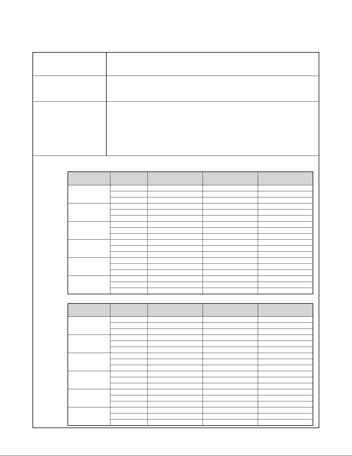
Approximate Memory Capacity and File sizes
• Snapshots (QV-R51)
File Size
(pixels)
2560x 1920
2560x 1712
(3:2)
2048x 1536
1600 x 1200
(UXGA)
1280 x 960
(SXGA)
640 x 480
(VGA)
• Snapshots (QV-R41)
File Size
(pixels)
2304 x 1712
2240 x 1680
2240 x 1488
(3:2)
1600 x 1200
(UXGA)
1280 x 960
(SXGA)
640 x 480
(VGA)
Quality
Fine
Normal
Economy
Fine
Normal
Economy
Fine
Normal
Economy
Fine
Normal
Economy
Fine
Normal
Economy
Fine
Normal
Economy
Quality
Fine
Normal
Economy
Fine
Normal
Economy
Fine
Normal
Economy
Fine
Normal
Economy
Fine
Normal
Economy
Fine
Normal
Economy
Approximate Image File
Size
2300 KB
1800 KB
1300 KB
2000 KB
1600 KB
1100 KB
1640 KB
1230 KB
630 KB
1050 KB
710 KB
370 KB
680 KB
460 KB
250 KB
190 KB
140 KB
90 KB
Approximate Image File
Size
1840 KB
1430 KB
1030 KB
1840 KB
1430 KB
1030 KB
1640 KB
1130 KB
660 KB
1050 KB
710 KB
370 KB
680 KB
460 KB
250 KB
190 KB
140 KB
90 KB
Built-in flash memory
9.7MB
4 shots
5 shots
7 shots
4 shots
5 shots
8 shots
5 shots
7 shots
14 shots
8 shots
12 shots
24 shots
13 shots
20 shots
35 shots
46 shots
61 shots
98 shots
Built-in flash memory
9.7MB
4 shots
6 shots
8 shots
4 shots
6 shots
8 shots
5 shots
8 shots
14 shots
8 shots
12 shots
24 shots
13 shots
20 shots
35 shots
46 shots
61 shots
98 shots
SD Memory Card*
64MB
25 shots
32 shots
44 shots
29 shots
36 shots
51 shots
35 shots
45 shots
88 shots
53 shots
79 shots
154 shots
82 shots
126 shots
220 shots
294 shots
386 shots
618 shots
SD Memory Card*
64MB
30 shots
40 shots
54 shots
30 shots
40 shots
54 shots
35 shots
50 shots
88 shots
53 shots
79 shots
154 shots
82 shots
126 shots
220 shots
294 shots
386 shots
618 shots
— 1 —
Page 4
• Movies (320 x 240 pixels)
Data Size
Recording Time
* Based on Matsushita Electric Industrial Co., Ltd. products. Capacity depends on card manufacturer.
* To determine the number of images that can be stored on a memory card of a different capacity, multiply the capacities in the
table by the appropriate value.
One Movie: 60 seconds maximum
Total Movie Time:
60 seconds maximum (built-in memory)
410 seconds maximum (SD 64MB memory card)*
150KB/second max.
Delete Single-file, all files (with protection)
Effective Pixels QV-R51: 5.00 million
QV-R41: 4.00 million
Imaging Element QV-R51: 1/1.8-inch square pixel color CCD
(Total pixels: 5.25 million)
QV-R41: 1/1.8-inch square pixel color CCD
(Total pixels: 4.13 million)
Lens/Focal Distance F2.8 (W) to 4.9 (T); f= 8 (W) to 24mm (T) (equivalent to approximately 39 (W) to 1 17 (T) for
35mm film)
Zoom 3X optical zoom; 4X digital zoom
(12X in combination with optical zoom)
Focusing Contrast-type Auto Focus (AF Mode (AF Area: Spot or Multi), Macro Mode), Infinity Mode;
focus lock; manual focus
Approximate Focus Range Normal 60 cm to ∞ (infinity) (2´ to ∞)
(from lens surface) Macro 10 cm to 70 cm (3.9˝ to 27.6˝)
In the Macro mode, the optical zoom range is 1X to 1.2X.
Manual Wide-angle: 10 cm to ∞ (infinity)
(3.9˝ to ∞)
Telephoto: 60 cm to ∞ (infinity)
(23.6˝ to ∞)
Exposure Control Light Metering Multi-pattern center-weighted, spot by CCD
Exposure Program AE
Exposure Compensation –2EV to +2EV (1/3EV units)
Shutter CCD electronic shutter; mechanical shutter, 1/8 to 1/2000 second (Changes in accordance
with recording mode and ISO sensitivity setting.)
• Shutter speed is different for the following BESTSHOT scenes.
Night Scene: 4 to 1/2000 second
Fireworks: 2 seconds (fixed)
Aperture Wide-angle: F2.8/4.8, auto switching
Telephoto: F4.9/8.4, auto switching
White Balance Automatic, fixed (4 modes), manual switching
Self-timer 10 seconds, 2 seconds, Triple Self-timer
Built-in Flash Flash Modes AUTO, ON, OFF, Red eye reduction
Flash Range ■ QV-R51
Wide Angle Optical Zoom: 0.6 to 3.2 meters (2.0´ to 10.5´)
Telephoto Optical Zoom: 0.6 to 1.8 meters (2.0´ to 5.9´)
(ISO Sensitivity: “Auto”)
— 2 —
Page 5
Built-in Flash Flash Modes AUTO, ON, OFF, Red eye reduction
Flash Range ■ QV-R41
Wide Angle Optical Zoom: 0.6 to 4.1 meters (2.0´ to 13.5´)
Telephoto Optical Zoom: 0.6 to 2.0 meters (2.0´ to 6.6´)
(ISO Sensitivity: “Auto”)
Recording Functions Snapshot; BESTSHOT; Movie
Monitor Screen 2.0-inch TFT color LCD
76,800 pixels (320 x 240)
Viewfinder Monitor screen and optical viewfinder
Timekeeping Functions Built-in digital quartz clock
Date and Time Recorded with image data
Auto Calendar To 2049
World Time City; Date; Time; Summer time;
162 cities in 32 time zones
Input/Output Terminals AC adaptor terminal (DC IN 3V)
USB port (Mini-B)
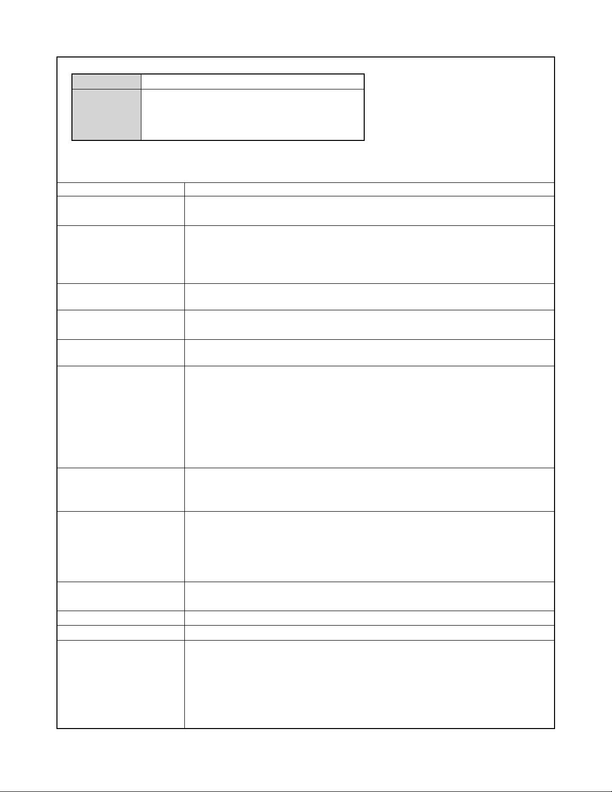
Power Requirements
Power Requirements Two AA-size rechargeable nickel-metal hydride batteries (HR-3U <Rated Capacitance 2100mAh>
Approximate Battery Life
and HR-3U <Rated Capacitance 2300mAh>)
Two AA-size lithium batteries
Two AA-size alkaline batteries AC adaptor(AD-C30)
Rechargeable Nickel-Metal
Hydride batteries
Number of Shots,
Continuous Recording*
(Recording Time)
Number of Shots,
Normal Recording*
(Recording Time)
Continuous Playback*
• The above figures are approximations only.
• The above guidelines are based on the following battery types:Rechargeable Nickel-Metal Hydride:
HR-3U (Rated Capacitance 2100 mAh) SANYO Electric Co., Ltd.
Alkaline: LR6 Matsushita Battery Industrial Co., Ltd.
• Battery life varies with brand.
The above values indicate the amount of time under the conditions defined below, until power automatically turns off due to battery
failure. They do not guarantee that you will be able to achieve this level of operation. Low temperatures shorten battery life.
*1 Continuous Recording Conditions
• Temperature: 23°C (73°F)
• Monitor screen: On
• Flash: Off
• Image recorded about every 10 seconds
*2 Normal Recording Conditions
• Temperature: 23°C (73°F)
• Monitor screen: On
• Zoom operation between full wide to full telephoto every 30 seconds, during which two images are recorded, one image
with flash; power turned off and back on every time 10 images are recorded.
*3 Continuous Playback Conditions
• Temperature: 23°C (73°F)
• Scroll one image about every 10 seconds
1
2
3
900 shots
(150 minutes)
240 shots
(120 minutes)
250 minutes
Alkaline batteries
240 shots
(40 minutes)
50 shots
(25 minutes)
130 minutes
— 3 —
Page 6

Power Consumption DC 3V Approximately 3.8 W
Dimensions 88.5 (W) x 60.5 (H) x 33.4 (D) mm
(3.5˝ (W) x 2.4˝ (H) x 1.3˝ (D))
(excluding projections)
Weight Approximately 168 g (5.9 oz) (excluding batteries and accessories)
Bundled Accessories Rechargeable nickel-metal hydride batteries (HR-3U <Rated Capacitance 2100 mAh>);
Charger unit (BC-5H); AC power cord; USB cable; Strap; CD-ROM; Basic Reference
Rechargeable nickel-metal hydride Battery(HR-3U)
(bundled)
Rated Voltage 1.2 V
Rated Capacitance 2100 mAh
Operating Temperature 0°C to 40°C (32°F to 104°F)
Range
Dimensions 14.35 (diameter) x 50.4 (H) mm (0.56˝ (diameter) x 1.98˝ (H))
Weight Approximately 29.0 g (1.0 oz)
* Each battery
Special battery chrger unit (BC-5H)
Power Requirement 100 to 240V AC, 0.08A, 50/60Hz
Output DC 1.2V, 550mA
Charging Temperature 0°C to 40°C (32°F to 104°F)
Chargeable Battery type Rechargeable nickel-metal hydride batteries (HR-3U)
Full Charge Times Approximately 4 hours
Dimensions 71 (W) x 75 (H) x 28 (D) mm
(2.8˝ (W) x 30˝ (H) x 1.1˝ (D))
(excluding projections)
Weight Approximately 75 g (2.6 oz)
Power Supply
• Use only the special HR-3U rechargeable nickel-metal hydride batteries to power this camera. Use of any other type of battery
is not supported.
• This camera does not have separate batteries for the clock. The date and time settings of the camera are cleared whenever
power is totally cut off (from both the batteries and AC adaptor). Be sure to reconfigure these settings after power is interrupted.
LCD Panel
• The LCD panel is a product of the latest LCD manufacturing technology that provides a pixel yield of 99.99%. This means that
less than 0.01% of the total pixels are defective (they do not turn on or always remain turned on).
Lens
• You may sometimes notice some distortion in certain types of images, such as a slight bend in lines that should be straight. This
is due to the characteristics of lens, and does not indicate malfunction of the camera.
— 4 —
Page 7
■
QV-R52
Image Files Format Snapshots: JPEG (Exif Ver.2.2); DCF (Design rule for Camera File system) 1.0 standard; DPOF
compliant
Movies: AVI (Motion JPEG)
Recording Media 9.7 MB built-in flash memory
SD Memory Card
MultiMediaCard
Image Size Snapshots: 2560 x 1920 pixels
2560 x 1712 (3:2)pixels
2048 x 1536 pixels
1600 x 1200 pixels
1280 x 960 pixels
640 x 480 pixels
Movies: 320 x 240 pixels
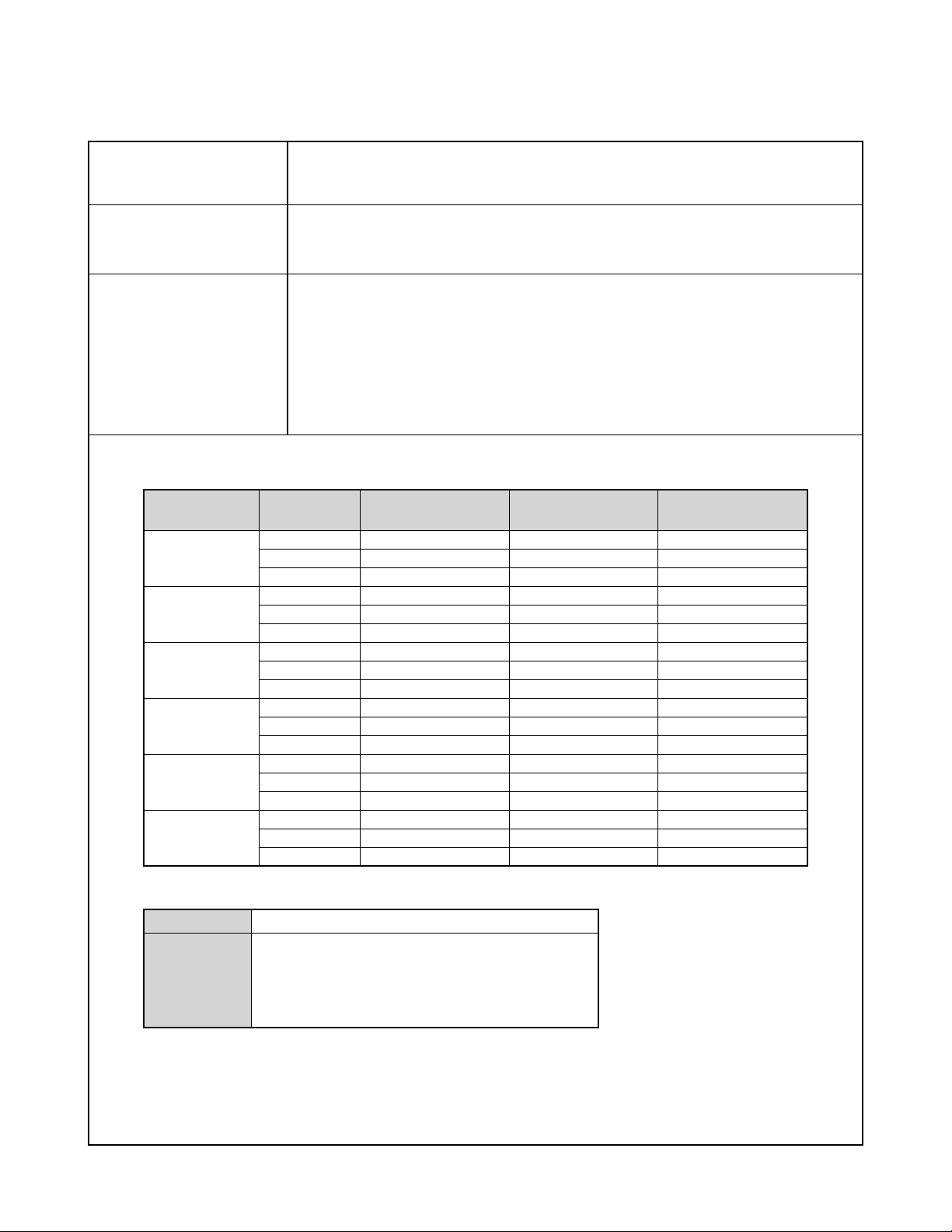
Approximate Memory Capacity and File sizes
• Snapshots
File Size
(pixels)
2560 x 1920
2560 x 1712
(3:2)
2048 x 1536
1600 x 1200
(UXGA)
1280 x 960
(SXGA)
640 x 480
(VGA)
Quality
Fine
Normal
Economy
Fine
Normal
Economy
Fine
Normal
Economy
Fine
Normal
Economy
Fine
Normal
Economy
Fine
Normal
Economy
Approximate Image
File Size
2300 KB
1800 KB
1300 KB
2000 KB
1600 KB
1100 KB
1640 KB
1230 KB
630 KB
1050 KB
710 KB
370 KB
680 KB
460 KB
250 KB
190 KB
140 KB
90 KB
Built-in flash memory
9.7MB
4 shots
5 shots
7 shots
4 shots
5 shots
8 shots
5 shots
7 shots
14 shots
8 shots
12 shots
24 shots
13 shots
20 shots
35 shots
46 shots
61 shots
98 shots
SD Memory Card*
64MB
25 shots
32 shots
44 shots
29 shots
36 shots
51 shots
35 shots
45 shots
88 shots
53 shots
79 shots
154 shots
82 shots
126 shots
220 shots
294 shots
386 shots
618 shots
• Movies (320 x 240 pixels)
Data Size
Recording
Time
* Based on Matsushita Electric Industrial Co., Ltd. products. Capacity depends on card manufacturer.
* To determine the number of images that can be stored on a memory card of a different capacity, multiply the capacities in the
table by the appropriate value.
150KB/second max.
One Movie: 60 seconds maximum
Total Movie Time:
60 seconds maximum (built-in memory)
410 seconds maximum (SD 64MB memory card)*
— 5 —
Page 8
Delete Single-file, all files (with protection)
Effective Pixels 5.00 million
Imaging Element 1/1.8-inch square pixel color CCD (Total pixels: 5.25 million)
Lens/Focal Distance Seven lenses in six groups, including an aspherical lens
F2.8 (W) to 4.9 (T); f= 8 (W) to 24mm (T) (equivalent to approximately 39 (W) to 117 (T) for
35mm film)
Zoom 3X optical zoom; 4 X digital zoom
(12X in combination with optical zoom)
Focusing Contrast-type Auto Focus (AF Mode (AF Area: Spot or Multi), Macro Mode), Infinity Mode; focus
lock; manual focus
Approximate Focus Range Normal 60 cm to ∞ (infinity) (2´ to ∞)
(from lens surface) Macro Approximately 10cm to 70cm (3.9˝ to 27.6˝) at wide angle
Approximately 60cm to 70cm (23.6˝ to 27.6˝) at telephoto
In the Macro mode, the optical zoom range is 1X to 1.2X.
Manual Optical Zoom Factor 1X: 10 cm to ∞ (infinity) (3.9˝ to ∞)
Optical Zoom Factor 3X: 60 cm to ∞ (infinity) (23.6˝ to ∞)
Exposure Control Light Metering Multi-pattern center-weighted, spot by CCD
Exposure Program AE
Exposure Compensation –2EV to +2EV (1/3EV units)
Shutter CCD electronic shutter; mechanical shutter, 1/8 to 1/2000 second (Changes in accordance with
recording mode and ISO sensitivity setting.)
• Shutter speed is different for the following BESTSHOT scenes.
Night Scene: 4 to 1/2000 second
Fireworks: 2 seconds (fixed)
Aperture Wide angle: F2.8/4.8, auto switching
Telephoto: F4.9/8.4, auto switching
White Balance Automatic, fixed (4 modes), manual switching
Sensitivity ISO50, ISO100, ISO200, ISO400, Auto
Self-timer 10 seconds, 2 seconds, Triple Self-timer
Built-in Flash Flash Modes AUTO, ON, OFF, Red eye reduction
Flash Range Wide Angle Optical Zoom: 0.6 to 3.2 meters (2.0´ to 10.5´)
Telephoto Optical Zoom: 0.6 to 1.8 meters (2.0´ to 65.9´)
(ISO Sensitivity: “Auto”)
Recording Functions Snapshot; BESTSHOT; Movie
Monitor Screen 2.0-inch TFT color LCD
84,960 pixels (354 x 240)
Viewfinder Monitor screen and optical viewfinder
Timekeeping Functions Built-in digital quartz clock
Date and Time Recorded with image data
Auto Calendar To 2049
World Time City; Date; Time; Summer time;
162 cities in 32 time zones
Input/Output Terminals AC adaptor terminal (DC IN 3V)
USB port (Mini-B)
— 6 —
Page 9
Power Requirements
Power Requirements Two AA-size alkaline batteries
Two AA-size rechargeable nickel-metal hydride batteries (HR-3UA <Rated Capacitance
2100mAh> and HR-3UB <Rated Capacitance 2300mAh>)
Two AA-size lithium batteries
AC adaptor (AD-C30)
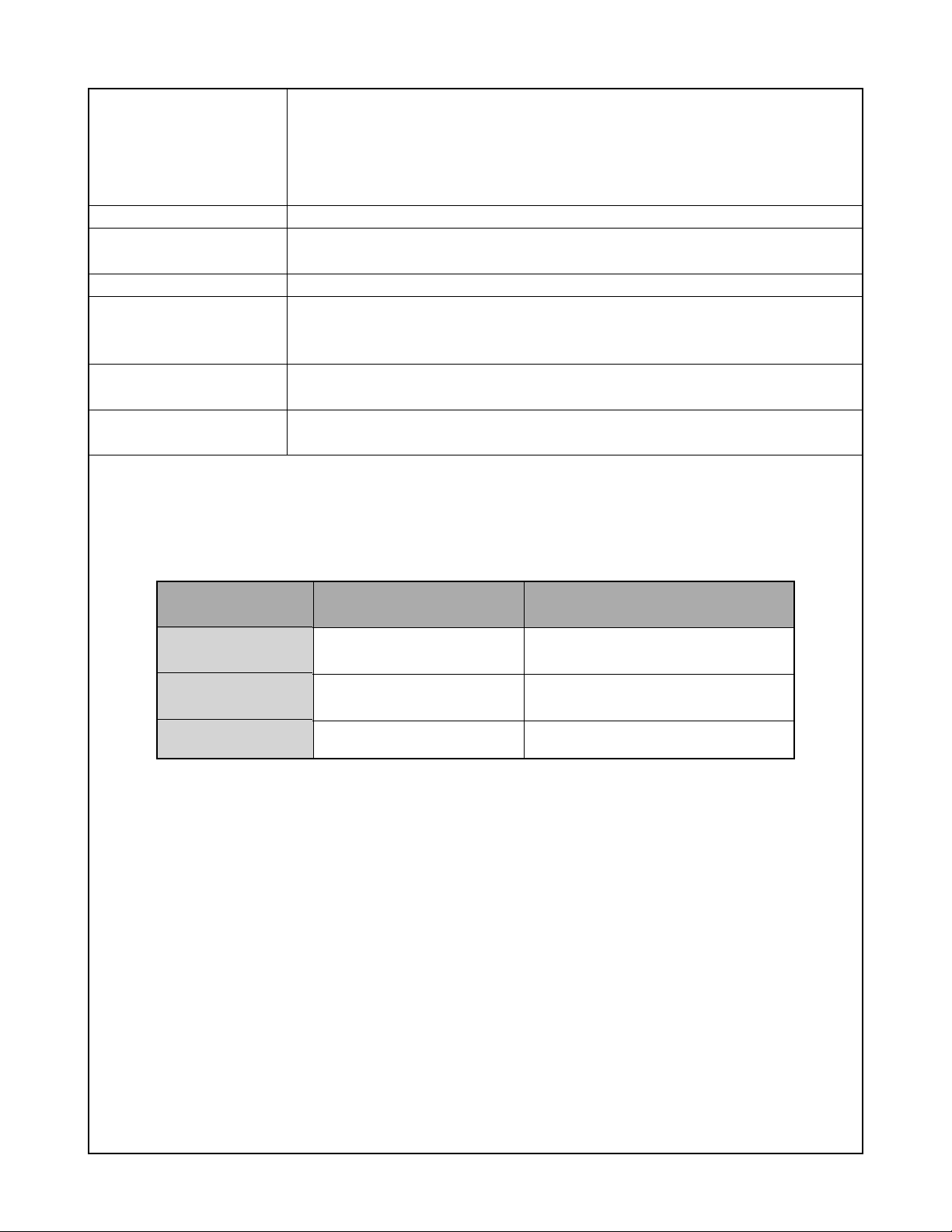
Approximate Battery Life:
The values below indicate the amount of time under the conditions defined below, until power automatically turns of f due to battery
failure. They do not guarantee that you will be able to achieve this level of operation. Low temperatures shorten battery life.
Operation
Number of Shots (CIPA Standard)
*1
(Operating Time)
Number of Shots, Continuous Recording
(Operating Time)
Continuous Snapshot Playback
The above figures are approximations only
•
The above guidelines are based on the following battery types
•
*3
Alkaline: LR6 Matsushita Battery Industrial Co., Ltd
Alkaline batteries
*2
.
(LR6)
50 shots
(25 minutes)
240 shots
(40 minutes)
130 minutes
.
MX1500 (AA) DURACELL ULTRA
Rechargeable Nickel-Metal Hydride:
HR-3UA (Rated Capacitance 2100 mAh) SANYO Electric Co., Ltd.
Battery life varies with brand
•
Storage Medium: SD Memory Card
•
.
Alkaline batteries
(MX1500 (AA))
90 shots
(45 minutes)
270 shots
(45 minutes)
120 minutes
:
Rechargeable Nickel-
Metal Hydride batteries
240 shots
(120 minutes)
900 shots
(150 minutes)
250 minutes
*1 Number of Shots (CIPA Standard)
• Temperature: 23°C (73°F)
• Monitor screen: On
• Zoom operation between full wide to full telephoto every 30 seconds, during which two images are recorded, one image
with flash; power turned off and back on every time 10 images are recorded.
*2 Continuous Recording Conditions
• Temperature: 23°C (73°F)
• Monitor screen: On
• Flash: Off
• Image recorded every 10 seconds, alternating full wide angle and full telephoto zoom
*3 Continuous Snapshot Playback Conditions
• Temperature: 23°C (73°F)
• Scroll one image about every 10 seconds
Power Consumption DC 3V Approximately 3.7 W
Dimensions 88.3 (W) x 60.4 (H) x 33.4 (D) mm
(3.5˝ (W) x 2.4˝ (H) x 1.3˝ (D))
(excluding projections)
Weight Approximately 168 g (5.9 oz) (excluding batteries and accessories)
Bundled Accessories Alkaline batteries (LR6); USB cable; Strap; CD-ROM; Basic Reference
— 7 —
Page 10

Power Supply
• SANYO Electric Co., Ltd. brand type HR-3UA or HR-3UB batteries are recommended when using rechargeable nickel metal
hydride batteries to power this camera. Proper operation cannot be guaranteed when other batteries are used.
• This camera does not have separate batteries for the clock. The date and time settings of the camera are cleared whenever
power is totally cut off (from both the batteries and AC adaptor). Be sure to reconfigure these settings after power is interrupted.
LCD Panel
• The LCD panel is a product of the latest LCD manufacturing technology that provides a pixel yield of 99.99%. This means that
less than 0.01% of the total pixels are defective (they do not turn on or always remain turned on).
Lens
• You may sometimes notice some distortion in certain types of images, such as a slight bend in lines that should be straight. This
is due to the characteristics of lens, and does not indicate malfunction of the camera.
— 8 —
Page 11
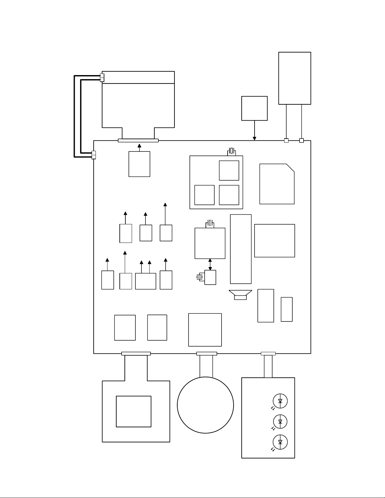
MAIN-PCB
Motor Driver
M50235HP
DOWN
Converter
VCC1.5
BACK UP
Capacitor
KONIKA
Lens Unit
×
3
SD
CCD
4M&5Mpix
1/1.8"
QV-R41 : ICX406AQF-D
QV-R51/R52 : ICX452AQF-C
15.0V
-7.5V
5.0V
C-FPC
ST-UNIT
Dry-Battery
(3.3V-2.1V)
Adapter
3.0V
20pin
22pin
VCOM
Amp
NJM2125
R
Self Timer
G
R
WIDE,TELE
21pin
SHUTTER
POWER
BUZZER
R-LEDG-LED
33pin
15V
BL (LED
×
3)
2.0" Digital I/F
LCD
VGH:15.0V
VSH:5.0V
VDD:3.0V
VCC15
VEE7.5
EVCC3.3
VCC5
VCC3.9
UP
Converter
UP
Converter
VCC3-1
VCC3-4
3.3V
1.5V
Stack MCM
M32934D4WG
13.5MHz
76C
SH
SDR
AM
8bit micon
M50235HP
4.0MHz
3.3V
32KHz
RTC
AD9948KCPRL
3.3V
V.Driver
CXD3440EN
3.3V
15.0V
-7.5V
CDS
SW
RIGHT LEFT
OK UP
DOWN MENU
REC PLAY
DISP
USC Jack
FLASH RAM
TC58DAM72F1XBJ3
UP
Converter
UP
Converter
UP
Converter
UP
Converter
+
-
BLOCK DIAGRAM
— 9 —
Page 12

TEST MODE
Note: Never perform the menu items unless otherwise instructed. Doing so may cause destruction
of the data inside, which will make the camera unusable.
■ To boot the test mode
1. While firmly pressing down both [MENU] and [DISP], turn the power on. Keep pressing both [MENU
and [TEST] until the main menu appears.
2 "POWER" button
1 "DISP" + "MENU" button
2. After the version appears, press the buttons in the order of [>], [>] and [MENU] to display the test
menu.
■ QV-R41 ■ QV-R51
PR : 04.06.23.13.19
LD : 1.45
MI : 20
++ KX865 ++
PR : 04.06.23.13.22
LD : 1.45
MI : 20
">" button -> ">" button -> "MENU" button
1 :VERSION INFO
2 :VIDEO OUT
3 :USB TCC TEST
4 :TEST MENU
5 :SOUND TEST
6 :BAYER MODE
7 :ROM UPDATE
8 :ADJ TEST
9 :REC-INFO
10 :TEST SCRIPT
11 :LAST MEMORY
12 :FORMAT
++ KX866 ++
"SET" button
"MENU" button
■ QV-R52
PR : 04.09.13.17.54
LD : 1.45
MI : 20
1 :KEY CHECK
2 :MEMORY CHECK
3 :COLOR CHECK
4 :MESSAGE CHECK
5 :LED CHECK
6 :SW&JACK CHECK
7 :MIC CHECK
8 :BENDI MASK
++ KX869 ++
[MENU] button
[>] button
— 10 —
Page 13

PROGRAM VERSION UPGRADING
1. To update the firmware version
1. Prepare the memory card which contains the firmware for QV-R41/R51/R52 in the root directory.
QV-R41: QV-R41.bin
QV-R51: QV-R51.bin
QV-R52: QV-R52.bin
2. Insert the above memory card in the camera, and then connect the AC adaptor or set a fully charged
battery in the camera.
3. While pressing [MENU], press the power button. Keep pressing [MENU] until “PROGRAM UPDATE”
appears in the display.
• The following appears.
• The version of the firmware in the memory card appears at the bottom of the display.
PROGRAM UPDATE
YES
NO
NEW VERSION IS
VER 1.00
4. Align the white cursor to [YES] by [쑿] and [쑼], and then press [SET].
• “NOW LOADING” appears in the display.
5. “COMPLETE” appears after the update finishes.
6. Remove the memory card after turning the power off once. T urn the power back on again while pressing
[MENU], and check the version.
(As of October 2004)
VER 1.00
(As of October 2004)
• “VER.1.00” appears.
7. If the version is correct, turn the power off.
8. Finally, check the operation by recording, playing back and deleting an image.
2. How to restore the firmware
1. Prepare the following firmware restoration program and change its name as follows;
QV-R41: rom865-040623.lbn 앶앸 jupiter.bin
QV-R51: rom866-040623.lbn 앶앸 jupiter.bin
QV-R52: rom869-040913.lbn 앶앸 jupiter.bin
2. Copy the above file to the root directory in the memory card.
3. Insert the memory card into the camera.
4. Connect the AD adaptor or set a fully charged battery in the camera.
5. Turn the power on while pressing the shutter release button.
If the power does not turn on only by pressing the power button, try inserting the battery while pressing
the shutter release button.
The LED next to the optical viewfinder changes from “green/red blinking” to “green steady”.
6. When the LED becomes “green steady”, the firmware restoration is finished.
Remove the AC adaptor or the battery and then turn the power off.
NOTE: It takes about ten seconds for this camera to completely turn the power off even by removing
the AC adaptor or the battery after the above firmware restoration.
Confirm that the LED which is “green steady” turns off.
— 11 —
Page 14

7. T urn the power on again while pressing [MENU] and [DISP]. The firmware restoration is complete after
the model name and the program version (PR:) appear in the opening screen of the test menu.
QV-R41 앶앸 ++KX865++
PR:04.06.23.13.19
QV-R51 앶앸 ++KX866++
PR:04.06.23.13.22
QV-R52 앶앸 ++KX869++
PR:04.09.13.17.54
8. Finally, start the camera normally to check the operation by recording, playing back and deleting an
image.
3. To install the firmware
Initially, firmware is not installed in the PCB supplied by the parts center.
Install the firmware into the PCB after replacing with a new one as shown in the procedures below.
NOTE: The camera does not turn on (only LED becomes “green blinking”) if the firmware is not installed
in the PCB.
<Writing the restoration program>
1. Copy the following software to the root directly of the SD card.
QV-R41: QV-R41.bin, rom865-040623.lbn
QV-R51: QV-R51.bin, rom866-040623.lbn
QV-R52: QV-R52.bin, rom869_040913.lbn
2. Change the name as follows;
“rom865-040623.lbn” to “jupiter.bin”
“rom866-040623.lbn” to “jupiter.bin”
“rom869_040913.lbn” to “jupiter.bin”
3. Insert the SD card into the camera.
4. While pressing the shutter release button, insert the battery.
The LED next to the optical viewfinder changes from “green/red blinking”, “green linking” to “green
steady”.
5. When the LED becomes “green steady”, turn the power off by removing the AC adaptor or the battery.
<System Initialize>
1. Boot the test mode.
2. Press [>] twice and then press [MENU].
3. Select “7: ROM UPDATE” and then press [SET].
4. Select “5: SYSTEMINITIALIZE” and then press [SET].
5. When the following message appears, press [SET].
SYSTEM INITIALIZE
START….
PUSH OK KEY?
6. The system initialize is performed and the following error message appears.
“SYSTEM ERROR”
7. Turn the power off.
<Writing the firmware>
1. While pressing [MENU], turn the power on.
2. When “PROGRAM UPDATE” appears, select “YES” and then press [SET].
3. “NOWLOADING” appears while the firmware is updated.
4. When “COMPLETE” appears, the firmware update is complete.
5. T urn the power on and off to check if the camera normally functions. If there is no problem, the firmware
update is successful.
— 12 —
Page 15

ADJ Tool
■ Introduction
Make sure to perform the adjustment by the USB ADJ Tool “adj03SSAW.exe” when replacing the lens
unit or the PCB.
Here the necessary software, driver and setting are explained to use “adj03SSAW.exe”.
Note that the tool, drivers etc. are available only for Windows.
1. Preparation
1-1. Prepare the necessary software, driver and DLL file.
1) Prepare the following three files.
• Common test driver for CASIO/PENTAX
[testmode_pentax_casio] folder uusbd.dll
uusbd.inf
uusbd.sys
• ADJ tool, USB DLL and ADJ setting file
[adj03SSAW] folder adj03SSAW.exe (ADJ tool itself)
uusbd.dll (USB DLL)
*.adt (ADJ setting file. Sorted by models)
* Place all files in the same folder.
2) Place the common test driver for CASIO/PENTAX in an appropriate place.
3) Place all of ADJ tool, USB DLL and ADJ setting file in the same folder.
1-2. Set the camera so that it recognizes the USB test mode.
1) Enter the test menu.
Turn the power on while pressing both [MENU] and [DISP].
Press [>], [>] and [MENU].
2) Move the cursor to “3: USB TCC TEST” and press [SET].
3) Move the cursor to “1: USB TCC ON” and press [SET].
4) The USB test mode flag is now saved in the camera. Turn the power off.
5) When the USB test mode flag is ON, the test menu appears first when the camera power is turned on.
* When turning the USB test mode flag OFF, set “2: USB TCC OFF” in the test menu.
1-3. Install the USB driver for the USB test mode in the computer.
(The following is an example using the Windows Me.)
1) Prepare the USB driver for the USB test mode.
2) Turn the camera power on which is set in the USB test mode as shown in 1-2 and let it enter the USB
test mode directly (the test menu appears right after the power is turned on).
3) Connect the camera in the above status to the computer by the USB cable.
4) The “Add new hardware” wizard appears.
5) Check “Designate the place for the driver (for users with sufficient knowledge)” and press “Next”.
6) Check “Search for the optimum driver for the device (recommended)”.
7) Check “Designate the place to search”, designate the place which contains “inf” file in the driver by
pressing “Reference” button, and then press “Next” button.
8) When “Universal USB Driver (VMEM manufacturer’s name)” appears upon message “Searching for
the driver file for the following devices”, press “Next” button.
— 13 —
Page 16

9) The file copy starts.
(If a message “uusbd.inf cannot be found” appears during the file copy, designate the same place as
in the step 7).
10) Press “Complete” button.
11) Right-click “My computer”, select “property”, and then open “Device manager”.
If “Universal USB Driver (VMEM manufacturer’s name)”,“USB device for UUSBD” can be found, the
computer has successfully recognized the driver.
12) The test driver can be used for both CASIO/PENTAX. Installing the test driver into either one enables
the other one to recognize it.
* How to uninstall the USB driver for the USB test mode
• Connect the camera to the computer while in the USB test mode so that the computer recognizes
the camera.
• Right-click “My computer”, select “Property” and open “Device manager”.
• Select “USB device for UUSBD” , and then “Universal USB Driver (VMEM manufacturer's name)”.
• Press “Delete” button to delete the driver.
• When using Windows98/98SE/Me, delete the following three files;
(NOTE! Do NOT delete “usbd.inf” and “usbd.sys”, whose names are much alike the following.)
C:windows / inf / uusbd.inf
C:windows / inf / other / KashiwanoUUSBD.inf
C:windows / system32 / drivers / uusbd.sys
• The driver has been successfully deleted.
1-4. Use the USB ADJ Tool
1) Prepare ADJ tool, USB DLL and ADJ setting file in the same folder.
2) Turn the camera power on which is set in the USB test mode and let it enter the USB test mode directly
(the test menu appears right after the power is turned on).
3) Boot “adj03SSAW.exe” and use it as follows;
• To read ADJ data from the camera
앶앸 Press “READ ($9)”.
There is no need to set the model by “FW Item Set”.
• To write ADJ data into the camera
앶앸 Press “WRITE ($8)”.
• To save ADJ data which is read
앶앸 Select “File” and “Save All ADJ”, and save it under an appropriate name.
• Open ADJ data which is saved
앶앸 1. Select the model by "FW Item Set", and then press "Load FW ->" button.
2. Select “File” and “Open”, and open the necessary file.
• Language” radio button can switch the language between Japanese and English in which the name
of the ADJ ITEM is displayed.
•“Radix” radio button can switch the data display between decimal and hexadecimal notations.
— 14 —
Page 17

2. How to use ADJ Tool when replacing Lens unit
Make sure to perform the following procedure after replacing the lens.
A floppy disk with the lens data is bundled in the spare parts of the lens unit.
1 Enter the TEST mode.
1. Turn the power on while pressing both "MENU" and "DISP" buttons.
2. Press "RIGHT" button, "RIGHT" button and "MENU" button while the
program version is displayed.
3. Select "3.USB TCC TEST", and press "SET" button.
4. Select "1. USB TCC ON", and press "SET" button.
5. Turn the power OFF.
2 Connect the camera to the computer by the USB cable.
3 Boot "adj03ssaw" .
4 Select the model name and click "Load FW " Key.
• QV-R41 앶앸 Kx865
• QV-R51 앶앸 Kx866
• QV-R52 앶앸 Kx869
5 Click "ADJ ALL READ", and display the data on the "adj03ssaw".
6 Find the No.1163, "V-COM DC".
7 Write down this value(data).
8 Replace the Lens unit.
9 Perform the above 1 to 3.
6
4
0 Select the model name and click "Load FW " Key.
• QV-R41 앶앸 Kx865
• QV-R51 앶앸 Kx866or Kx869
• QV-R52 앶앸 Kx866or Kx869
A From "File/Open", open the bundled floppy disk, and transfer the data to
the "adj03ssaw".
B Find the No.1163,"V-COM DC"
C Change the data to the former value.(Refer to 7).
D Click "WRITE" button of "ADJ ALL".
If error happens on KX866;
Change the model name KX866 to KX869.
Try to click "WRITE" button again.
E After adjustment, change "1. USB TCC ON" to "2. USB TCC OFF".
A
D
— 15 —
Page 18

3. How to use ADJ Tool when replacing MAIN PCB
Firmware is not installed in spare parts.
1 Enter the TEST mode.
1. Turn the power on while pressing both "MENU" and "DISP" buttons.
2. Press "RIGHT" button, "RIGHT" button and "MENU" button while the
program version is displayed.
3. Select "3.USB TCC TEST", and press "SET" button.
4. Select "1. USB TCC ON", and press "SET" button.
5. Turn the power OFF.
2 Connect the camera to the PC by the USB cable.
3 Boot "adj03ssaw".
4 Select the model name and click "Load FW " Key.
• QV-R41 앶앸 Kx865
• QV-R51 앶앸 Kx866
• QV-R52 앶앸 Kx869
5 Click "ADJ ALL READ", and display the data on the "adj03ssaw".
6 Save the data.
7 Replace the MAIN PCB.
8 Writing the Firmware.
Write the firmware into a spare part after replacing one.
NOTE: If a battery is inserted without the firmware, only LED blinks
green and the camera does not operate.
9 Perform the above 1 to 3.
0 Select the model name and click "Load FW " Key.
• QV-R41 앶앸 Kx865
• QV-R51 앶앸 Kx866
• QV-R52 앶앸 Kx869
A Open the file which is saved above, and display the data on the
"adj03ssaw".
B Click "WRITE" button of "ADJ ALL".
C After adjustment, change "1. USB TCC ON" to "2. USB TCC OFF".
6
5
4
A
— 16 —
B
Page 19

VCOM DC ADJUSTMENT
■ Purpose
Readjust the VCOM value to minimize the flicker of the LCD after replacing the LCD or the main PCB.
■ Necessary tools
1. Camera (Charge its battery fully)
2. Photo diode (S2281-01) : See Fig 1.
3. Photo sensor amp (C2719) : See Fig 2.
4. BNC-BNC cable (E2573) x 2 : See Fig 3.
5. 9-volt alkaline battery (6LR61Y) x 2 : See Fig 4.
6. Oscilloscope
■ Preparation
1. The three tools can be obtained from the following global site.
Photo diode (S2281-01)
Photo sensor amp (C2719)
BNC-BNC cable (E2573)
www.hamamatsu.com/
2. 9-volt alkaline battery is a standard one, but can be obtained from the following global site as well.
www.panasonic.co.jp/global/
Fig1 Photo Diode (S2281-01) Fig2 Photo Sensor Amp (C2719)
Fig3 BNC-BNC Cable (E2573) Fig4 6LR61Y
— 17 —
Page 20

■ Procedure
1:LCD
2:SHUT
3:AWB
.
.
.
1:VCOM OK
.
.
.
OK -> Register Write
VCOM = 0xca
This value is an example and differs by products.
Figure (a)
Figure (b)
Figure (c)
Figure (d)
1 :VERSION INFO
2 :VIDEO OUT
3 :USB TCC TEST
4 :TEST MENU
5 :SOUND TEST
6 :BAYER MODE
7 :ROM UPDATE
8 :ADJ TEST
9 :REC-INFO
10 :TEST SCRIPT
11 :LAST MEMORY
12 :FORMAT
1. Camera setting
a) Turn the power on while pressing MENU and DISP.
After pressing “Right” key twice, press MENU.
Figure (a) appears.
b) Select “8 : ADJ_TEST” and then press SET.
(See Figure (b).)
c) Next, select “1. LCD” and then press SET.
(See Figure (c).)
2. Connecting the TOOL
d) Pressing SET causes the right figure to appear.
(See Figure (d).)
a) Place two 9-volt alkaline batteries in C2719.
b)
Connect the output terminal of C2719 to the channel terminal of the oscilloscope by the BNC-BNC cable.
c) Connect the input terminal to the Photo Diode by the BNC cable.
d) Turn the oscilloscope and C2719 on.
* Pull the ON/OFF switch of C2719 this way and raise/lower it. (See below Figure.)
— 18 —
Page 21

3. Measurement
a) Connect S2281-01 to the camera’s LCD monitor (see below).
AC Waveforms appear on the monitor screen of the oscilloscope.
* Change the Rf range of C2719 in case the range does not match.
Photo diode
S2281-01
INPUT OUTPUT
Oscilloscope
Photo sensor amp
CAMERA
BNC-BNC cable
LCD
Minimize the
ripple components
b) After AC waveforms of the oscilloscope appear , minimize it by pressing the camera’s up/down buttons
(see the picture).
Make sure to visually check if it has been minimized.
"Up" button
"Down" button
After it has been minimized, press SET key.
The screen in the right figure appears and the new VCOM
is written (VCOM adjustment is finished.).
Return to the previous display by pressing MENU or PW key.
OK -> Register Write
VCOM = 0xca
ADJ DATA SET!
This value is only an example, and differs by products.
— 19 —
Page 22

CURRENT CONSUMPTION
(1) Current consumption (DC in = 3.70 ~ 4.05 [V])
• Make sure that current consumption is less than 250 mA in PLAY mode.
• Make sure that current consumption is less than 350 mA in REC mode.
• Make sure that current consumption is less than 0.5 mA when power is turned OFF.
(2) The battery indicator changes according to the voltages as follows.
• DC in = less than 3.68 ± 0.02V: (PLAY mode)
• DC in = less than 3.58 ± 0.02V: (PLAY mode)
• DC in = less than 3.43 ± 0.02V: (PLAY mode)
THE COUNTERMEASURE FOR "SYSTEM ERROR"
System error may occur when the battery is removed while data is written to the internal memory.
■ PROCEDURE
1. Initialize the system.
a) Enter the TEST mode.
b) Select "7:ROM UPDATE" and press SET button.
c) Next, select "5:SYSTEM INITIAL" and press SET button.
d) The following message appears.
SYSTEM INITIALIZE
START
PUSH OK KEY?
e) Press SET button and System is initialized.
But the message, "SYSTEM ERROR", still appears on the monitor.
2. Write firmware.
Refer to the "1. To update the firmware version" on page 7.
Write the firmware.
If the TEST mode boots automatically, change "USB TCC ON" to "USB TCC OFF".
Replace the Main PCB if the camera does not recover.
...
— 20 —
Page 23

DISASSEMBLY
■ There are several types of screws. Make sure to use the
correct ones.
■ It is a good idea to sort them as shown in the figure when
disassembling.
1. Remove the batteries.
■ Removing the rear panel
2. Remove six screws.
Screws (S3)
Screws (S4)
3. Remove the rear panel.
4. Remove the connector cover and the AC jack cover.
Screws (S2)
Screws (S3)
AC jack cover
Rear panel
Connector cover
— 21 —
Page 24

5. Remove one screw (S1) and then the strap board.
Screw (S1)
■ Removing the front panel unit
6. Remove two screws (S2).
Strap board
Screws (S2)
7. Unsolder two battery plates.
Battery plates
8.
While opening the case in the direction of the arrow, remove the electronic block from the front panel unit.
NOTE: Make sure that the hooks are snapped
together when assembling.
Hooks
— 22 —
Page 25

NOTE: Make sure to discharge the strobe condenser when removing the front panel.
■ Disassembling the front panel unit
9. Remove two screws (S3) and then remove the tripod sock.
Screws (S3)
10. Remove four screws (S5) and then remove the cam ring and the upper case.
Screws (S5)
Screws (S5)
Cam ring
11. Remove two screws (S2) and then remove the center case.
Tripod sock
Upper case
Center case
Screws (S2)
— 23 —
Page 26

■ Removing the LCD
12. Lift the LCD unit by a pair of tweezers and then remove the LCD unit from the LCD frame.
LCD frame
Concave part
Channel
13. Unsolder the two lead wires.
14. Remove the connector.
15. Remove the LCD unit.
Connector
NOTE: Make sure to insert the connector tightly
when assembling, or the display will be
defective.
Red cord
Black cord
16. Remove three screws and then remove LCD frame.
screws
screws
— 24 —
Page 27

■ Removing the PCB
17. While heating the upper part of the earth board by a soldering iron, lift up the earth board by a pair of
tweezers and remove it.
Earth board
NOTE: Temporarily fixing the earth board by a screw
makes it easier to solder when assembling.
18. Remove the connector.
19. Remove one screw (S7).
20. Remove the connector.
Clamp board
Screw (S7)
— 25 —
Page 28

21. Remove the PCB
■ Disassembling the battery case
22. Remove one screw (S8) and then remove the battery case.
Screw (S8)
PCB
Battery case
23. Remove one screw (S9) and then disassemble the battery case (See the figures below for the position of
the hooks).
Screw (S9)
Battery cover
— 26 —
Page 29

■ Removing the lens unit
24. Remove two screws (S10) and then remove the lens unit.
Strobe unit
Screws (S10)
(with CAPA holder)
Lens unit
NOTE: Insert the convex portion into the concave portion tightly as shown in the figures below
when assembling.
B
Insert A into B tightly.
A
D
Insert C into D tightly.
C
— 27 —
Page 30

EXPLODED VIEW
S2
S1
S2
11
10
4
5
14
15
7
9
8
S2
6
3
17
2
1
16
12
S3
13
S2
18
S3
S4
S3 S3
19
21 20
22
— 28 —
Page 31

N Item Parts Code Parts Name Specification QTY Price R Remark
PARTS PRICE LIST
QV-R41 QV-R51 Code
N 1 10149329 PCB ASSY/MAIN TK-RJK505726*001 1 1 DT A
2 10127443 COVER/JACK RJK504662-001V01 1 1 AE C
3 10126467 STRAP BOARD RJK504626-001V01 1 1 AK C
N 4 10147342 STROBE UNIT XEST-K865-1-ST 1 0 CN C
N 4 10147336 STROBE UNIT XEST-K866-1 0 1 CI C
5 10135336 EARTH BOARD RJK504747-001V01 1 1 AA C
N 6 10149323 ASSY/BATTERY BOX TK-RJK505732*002 1 0 BA C
N 6 10149334 ASSY/BATTERY BOX TK-RJK505732*001 0 1 BA C
N 7 10149321 LENS UNIT TK-RJK505724*002 1 0 EA A
N 7 10149328 LENS UNIT TK-RJK505724*001 0 1 ED A FD attached
N 8 10149325 ASSY/UPPER CASE TK-RJK505736*002 1 0 AF C
N 8 10149336 ASSY/UPPER CASE TK-RJK505736*001 0 1 AG C
N 9 10149327 ASSY/FRONT PANEL TK-RJK505737*002 1 0 BS B
N 9 10149337 ASSY/FRONT PANEL TK-RJK505737*001 0 1 BT B
N 10 10135919 GRIP RJK504661-001V02 1 0 AJ C
N 10 10142609 GRIP RJK505463-001V01 0 1 AL C
11 10134229 TAPE RJK504706-001V02 1 1 AA C
N 12 10151947 CAM RING RJK504660-004V02 1 0 BB C
N 12 10151946 CAM RING RJK504660-003V02 0 1 BC C
13 10126478 TRIPOD SOCK RJK504763-001V01 1 1 AM C
N 14 10149324 ASSY/CENTER CASE TK-RJK505735*002 1 0 BN B
N 14 10149335 ASSY/CENTER CASE TK-RJK505735*001 0 1 BN B
15 10127445 COVER/CONNECTOR RJK504663-001V01 1 1 AE C
16 10127436 HOLDER/CAPA RJK504693-001V01 1 1 AB C
N 17 10149338 ASSY/BATTERY COVER TK-RJK505734*001 1 1 AP B
N 18 10149331 ASSY/REAR PANEL TK-RJK505728*001 1 1 CA B
N 19 10153693 PLATE/RATING RJK504669-005V01 1 0 AA C
N 19 10153694 PLATE/RATING RJK504669-006V01 1 0 C US only
N 19 10153668 PLATE/RATING RJK504669-002V01 0 1 AA C Except US
N 19 10153669 PLATE/RATING RJK504669-003V01 0 1 C US only
N 20 10149330 LCD ASSY TK-RJK505727*001 1 1 DG B
N 21 10153672 SUPPORT/LCD RJK505467-001V01 1 1 AA B
N 22 10153671 FRAME/LCD RJK505466-001V01 1 1 AB C
S1 10086282 SCREW RJK502970-001V01 1 1 AA C
S2 10086285 SCREW RJK502971-001V01 5 5 AA C
S3 10131119 SCREW RJK502970-004V01 5 5 AA C
S4 10086284 SCREW RJK502970-003V01 2 2 AA C
ACCESSORY
N - 10153691 CD-ROM CK866DBA01R 1 1 AG C US only
N - 10153692 CD-ROM CK866DCA01R 1 1 AG C Except US
- 10090421 USB CABLE UC-K861-LG10 1 1 AQ C
- 10136903 CORD/AC CBL-K864-AC-JU 1 1 AI C Blade type
- 10136905 CORD/AC CBL-K864-AC-EU 1 1 AJ C EU type
- 10136906 CORD/AC CBL-K864-AC-UK 1 1 AX C UK type
- 10136907 CORD/AC CBL-K864-AC-CH 1 1 AJ C China type
- 10126486 CHARGER NC-MDR01JUCA 1 1 BV C *1
- 10126488 CHARGER NC-MDR01WCA 1 1 BV C *2
- 10127402 NI-MH BATTERY HR-3U-KSO-4E 2 2 AR B
- 10090412 STRAP ST-K861 1 1 AF C
FD attached
Except US
N : New parts
*1: Blade type AC cord is built-in.(For US)
*2: AC cord is not built-in.
- 29 -
Page 32

QV-R52
N Item Parts Code Parts Name Specification QTY Price R Remark
Code
N 1 1018 4415 PCB ASSY/MAIN TK-RJK506801*002
2 1012 7443 COVER/JACK RJK504662-001V01
3 1012 6467 STRAP BOARD RJK504626-001V01
4 1014 7336 STROBE UNIT XEST-K866-1
5 1013 5336 EARTH BOARD RJK504747-001V01
N 6 1017 4885 BOX ASSY/BATTERY TK-RJK506807*001
N 7 1018 4414 LENS UNIT
N 8 1018 4419 CASE ASSY/UPPER TK-RJK506811*002
N 9 1018 4420 PANEL ASSY/FRONT TK-RJK506812*002
N 10 1014 2609 GRIP RJK505463-001V01
N 11 1015 2188 TAPE RJK506125-001V01
N 12 1018 1176 CAM RING RJK504660-006V02
13 1012 6478 TRIPOD SOCK RJK504763-001V01
N 14 1018 4418 CASE ASSY/CENTER TK-RJK506810*002
15 1012 7445 COVER/CONNECTER RJK504663-001V01
16 1012 7436 HOLDER/CAPACITOR RJK504693-001V01
N 17 1017 4886 COVER ASSY/BATTERY TK-RJK506809*001
N 18 1018 4417 PANEL ASSY/REAR TK-RJK506803*002
N 19 1018 1218 LABEL/RATING RJK504669-014V01
N 19 1018 1173 LABEL/RATING RJK504669-015V01
N 20 1018 4416 LCD ASSY TK-RJK506802*002
21 1015 3672 SUPPORT/LCD RJK505467-001V01
22 1015 3671 FRAME/LCD RJK505466-001V01
S1 1008 6282 SCREW RJK502970-001V01
S2 1008 6285 SCREW RJK502971-001V01
S3 1013 1119 SCREW RJK502970-004V01
S4 1008 6284 SCREW RJK502970-003V01
RJK506799*002 TK 1
1
DT A
1
AE C
1
AK X
1
CI C
1
AA X
1
BF C
ED A FD attached
1
AE C
1
BS C
1
AL C
1
AA C
1
BC C
1
AM C
1
BJ B
1
AE C
1
AB X
1
AT C
1
CB C
1
AA C For EU/US
1
AA C Except EU/US
1
DG B
1
AA X
1
AB X
1
AA X
5
AA X
5
AA X
2
AA X
ACCESSORY
N - 1018 1161 CD ROM CK869DCA01R 1 AE C
- 1009 0421 USB CABLE UC-K861-LG10 1 AQ C
- 1018 1159 BATTERY/ALKALINE LR6GW/2ST 1 AE B 1set : 2pcs
- 1009 0412 STRAP ST-K861 1 AF X
N New Parts
- 30 -
Page 33

PRINTED CIRCUIT BOARDS
MAIN PCB
— 31 —
Page 34

MAIN PCB (1/2)
SCHEMATIC DIAGRAMS
— 32 —
Page 35

MAIN PCB (2/2)
— 33 —
Page 36

Ver.1 : Mar. 2004
• Correction of page 29.
Ver.2 : Oct. 2004
• QV-R52 has been added.
• The program for QV-R41/R52 has been changed. (P10 ~ P12)
Ver.3 : Dec. 2004
• Correction of the ADJ TOOL. (P15)
CASIO TECHNO CO.,LTD.
Overseas Service Division
6-2, Hon-machi 1-Chome
Shibuya-ku, Tokyo 151-8543, Japan
 Loading...