

Page 1
MA-100
100 TONES
KEYBOARD
WIND
10
SAMBA WHISTLE
11 WHISTLE
12 QUENA
13 FLUTE
14 FLUTE-VIB
15 OCARINA
16 BAGPIPE
17
HARMONICA
18
CHORUS
19
BRASS-STRINGS
VOLUME
MIN MAX
STRING
20
WARM STRINGS
21 STRINGS
22 VIOLIN
23 VIOLIN-VIB
24 CELLO
25
ELEC GUITAR
26
JAZZ GUITAR
27
MUTE GUITAR
28
METAL GUITAR
29 SLAP BASS
00 PIANO
01 ELEC PIANO
02 FUNKY CLAVI
03 HARPSICHORD
04 ELEC ORGAN
05 JAZZ ORGAN
06 PIPE ORGAN
07
CHURCH ORGAN
08
STREET ORGAN
09 ACCORDION
MODE
POWER OFF FINGERED
NORMAL CASIO
CHORD
CC#EbDEFF#GAbABbBCC#DEbEF£CHORD
30
ELEC BASS
31
WOOD BASS
32
SNARE BASS
33 MANDOLIN
34 BANJO
35
SITAR
36
UKULELE
37
HARP
38
TAISHOKOTO
39 SHAMISEN
BRASS
40
BRASS ENS
41
WARM BRASS
42 TRUMPET
43 TUBA
44 BRASS HIT
45
WIND ENS
46
ENGLISH HORN
47
OBOE
48
BASSOON
49 CLARINET
PERCUSSION
50 VIBRAPHONE
51 MARIMBA
52 CHURCH BELLS
53 BELLS
54 TOM
55 ROCK DRUM
56 SWING DRUM
TRIANGLE
57
58
SAMPLE PERCUSSION
59 MATSURI
STOP
SYNTH-SOUND
60 SYNTH-CELESTA
61 SYNTH-CLAVI
SYNTH-ACCORDION
62
63 SYNTH-PIANO
64 SYNTH-BRASS
65 SYNTH-REED
66 SYNTH-LEAD
67 SYNTH-GUITAR
68 SYNTH-STRINGS
69 SYNTH-BASS
TEMPO
TONE/RHYTHM SELECT TONE
GRASS HARMONICA
70
71 FANTASY
WAW VOICE
72
73 TWINKLE ECHO
74 METAL LEAD
75 PLUNK EXTEND
76 COSMIC DANCE
77 CATHEDRAL
78 POP LEAD
79 PEARL DROP
SOUND EFFECT
80 AIRPLANE
81 AMBULANCE
82 INSECT
EMERGENCY ALARM
83
84 LASER BEAM
COSMIC SOUND
85
86 TELEPHONE
87 CAR HORN
COMPUTER SOUND
88
89
MOTORCYCLE
POLY/TEXTURE43210
98765
RHYTHM DEMOFILL-IN START/
KEYBOARD SPLIT
90
BASS/VIBRAPHONE
91
BASS/PIANO
92
BASS/TRUMPET
93
BASS/SYNTH-LEAD
94
BASS/ELEC ORGAN
95
STRINGS/BRASS
96 CHORUS/BELLS
BRASS/SYNTH-REED
97
98
PIANO/FLUTE
99
STRINGS/OBOE
100 RHYTHMS
ROCK
00 ROCK 1
01 ROCK 2
02 HARD ROCK 1
03 HARD ROCK 2
04 HARD ROCK 3
05 HEAVY METAL 1
06 HEAVY METAL 2
8 BEAT 1
07
08
8 BEAT 2
09
8 BEAT 3
OLDTIME ROCK
50 ROCK'N'ROLL 1
51 ROCK'N'ROLL 2
52 ROCK'N'ROLL 3
53 MERSEY BEAT
54 SLOW ROCK 1
55 SLOW ROCK 2
56 SLOW ROCK 3
DOO-WOP
57
58
RHYTHM & BLUES
59
BLUES
16 BEAT
10
16 BEAT 1
11
16 BEAT 2
12
16 BEAT 3
13
16 BEAT 4
14
16 BEAT 5
15
16 BEAT 6
16
16 BEAT 7
17
16 BEAT 8
18 LATIN
19 LATIN
SWING
60 SWING 1
61 SWING 2
62 SWING 3
63 SWING 4
64 BIG BAND 1
65 BIG BAND 2
66 BIG BAND 3
JAZZ WALTZ
67
68
TAP-DANCE BEAT
69
BOOGIE-WOOGIE
16 BEAT 1
16 BEAT 2
DISCO
20
70'S DISCO
21
EURO-BEAT 1
22
EURO-BEAT 2
23
EURO-BEAT 3
24
EURO-BEAT 4
25
HIP-HOP 1
26
HIP-HOP 2
27
HIP-HOP 3
28 TECNO-POP
29 TECNO-POP
LATIN
70 SAMBA 1
71 SAMBA 2
BOSSA NOVA 1
72
73
BOSSA NOVA 2
74 TANGO
75 BEGUINE
76 MAMBO
77 RUMBA
CHA-CHA-CHA
78
79
HABANERA
1
2
DISCO
30
FUNK 1
31
FUNK 2
32
FUNK 3
33
FUNK 4
34
FUNK 5
35
FUNK 6
36
FUNK 7
37
FUNK 8
38
FUNK 9
39
FUNK 10
VARIOUS
80 REGGAE 1
81 REGGAE 2
82 SALSA 1
83 SALSA 2
84 SALSA 3
85 FOLKLORE 1
86 FOLKLORE 2
87 COUNTRY
ENKA
88
89
POLKA
POPS
40 POPS
1
41 POPS
2
42 POPS
3
43 POPS
4
44 POPS
5
45 30' POPS
46 60' POPS 1
47 60' POPS 2
48 60' POPS 3
49 60' POPS 4
90 GALOP 1
91 GALOP 2
92 MARCH 1
93 MARCH 2
94 WALTZ 1
95 WALTZ 2
96 CLASSICAL
ELEC CLASSICAL
97
98
STREET ORGAN
99
KOTO
MA-100
ELECTRONIC KEYBOARD
Page 2
CONTENTS
Specifications ..................................................................2
Block Diagram ................................................................. 3
Circuit Description ...........................................................3
Troubleshooting...............................................................5
Major Waveforms ............................................................8
Schematic Diagrams .......................................................9
PCB View ......................................................................11
Exploded View...............................................................12
Parts List ....................................................................... 13
SPECIFICATIONS
GENERAL
Number of keys: 49
Polyphonic: 8-note
Preset tones: 100
Auto-rhythms: 100
Auto-accompaniment: CASIO Chord/Fingered
Demonstration tune: Classical Medley
Built-in speakers: 8 cm dia. 1.1 W Input Rating: 1 pc.
Terminal: AC Adapter Jack (DC 7.5 V)
Power source: 2-way AC or DC source
AC: AC adapter
DC: 5 AA size dry batteries
Power consumption: 1.8 W
Dimensions(HWD): 63 x 650 x 217 mm
(2-1/2 x 25-9/16 x 8-1/2 inches)
Weight: 1.4 kg (3.1 lbs) excluding batteries
ELECTRICAL
Current drain with 9V DC:
No sound output 34 mA ± 20%
Maximum volume 110 mA ± 20%
with keys C3, D3, E3 and F3 pressed
in Church Organ tone, Volume; Maximum
Speaker Output Level at 4 Ω load: 510 mV ± 20 %
with key E2 pressed in Church Organ tone
Volume; Maximum
Minimum operating voltage: 5.5 V
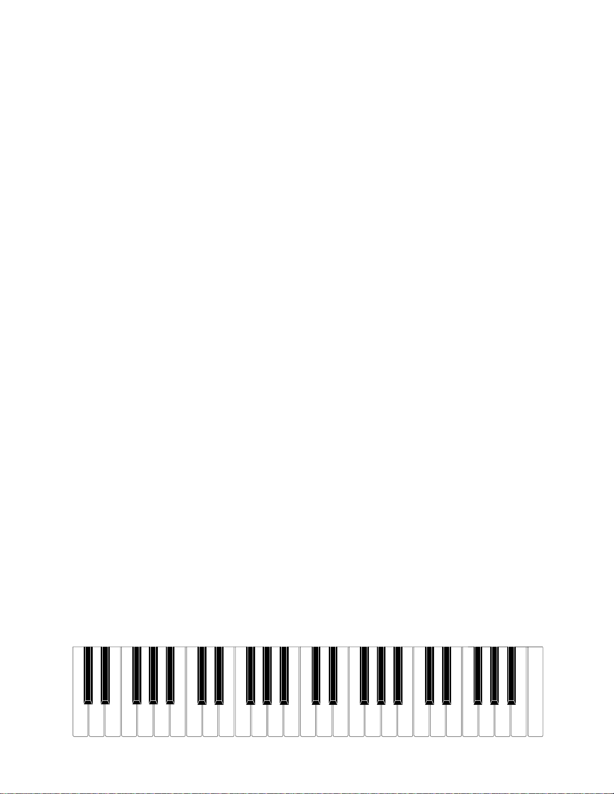
Nomenclature of Keys
F#3 G#3 A#3 C#4 D#4 F#4 G#4 A#4 C#5 D#5 F#5 G#5 A#5
F3 G3 A3 B3 C4 D4 E4 F4 G4 A4 B4
C2
C#2
D2
D#2
E2
F2
G2
B2 C3 D3 E3
A2
C#3A#2G#2F#2
D#3
C5 D5 E5 F5 G5 A5 B5
C6
— 2 —
Page 3
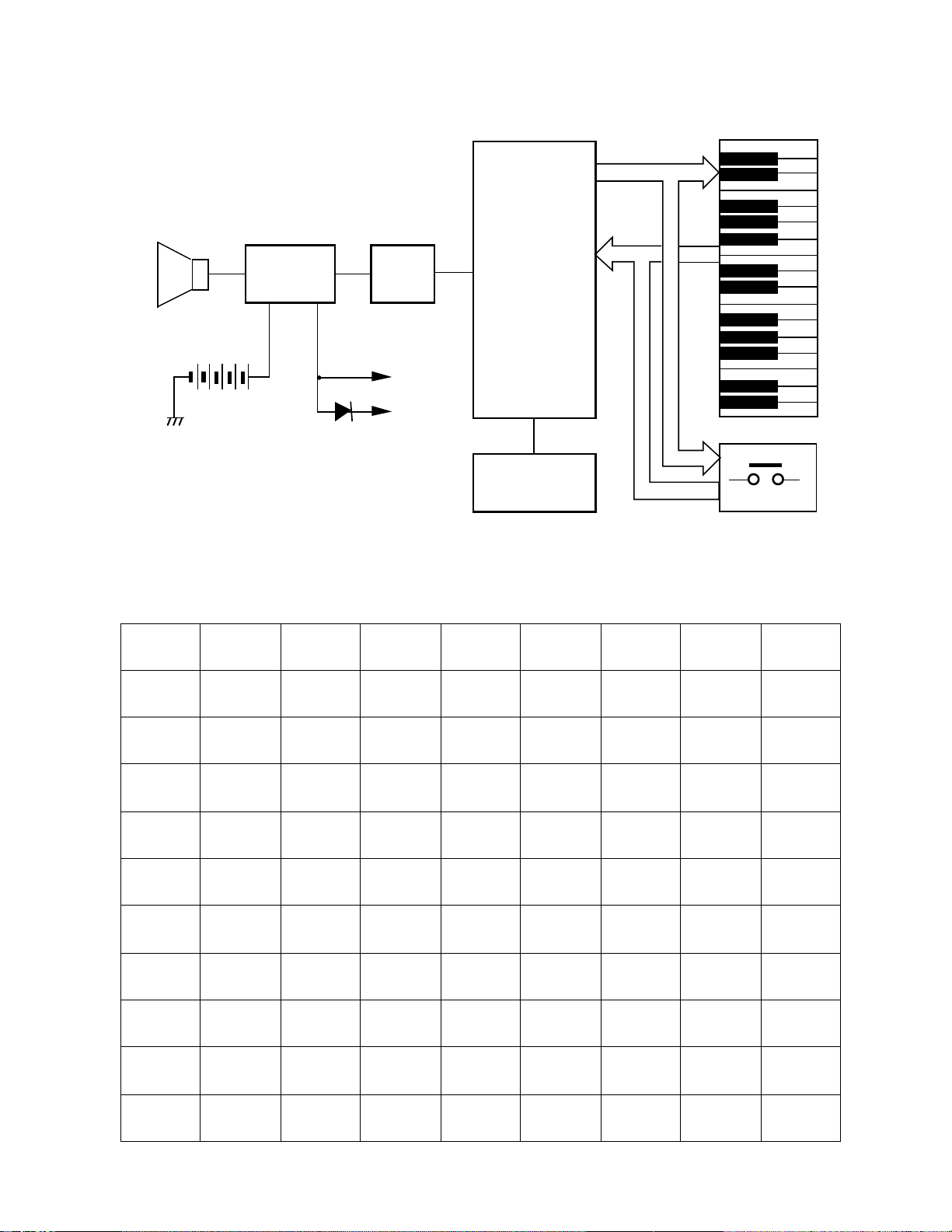
Speaker
Amplifier
AN8053N
IC101
BLOCK DIAGRAM
CPU
Filter
Q101
VDD
MSM6387-22
MSM6387-13
LSI101
KO0 ~ KO9
KO0 ~ KO8
KI0 ~
KI7
AVDD
Oscillator
Q102, X101
CIRCUIT DESCRIPTION
Key Matrix
KI0 KI1 KI2 KI3 KI4 KI5 KI6 KI7
KO0 0 1 C2 C#2 D2 D#2 E2 F2
KO1 2 3 F#2 G2 G#2 A2 A#2 B2
KO2 4 5 C3 C#3 D3 D#3 E3 F3
KO3 6 7 F#3 G3 G#3 A3 A#3 B3
Keyboard
Buttons
KO4 8 9 C4 C#4 D4 D#4 E4 F4
KO5 Tone Rhythm F#4 G4 G#4 A4 A#4 B4
KO6
KO7
Tempo
Up
Start/
Stop
Tempo
Down
C5 C#5 D5 D#5 E5 F5
Fill-In F#5 G5 G#5 A5 A#5 B5
KO8 Demo C6
KO9 Normal Fingered
— 3 —
CASIO
Chord
Page 4
CPU (LSI101: MSM6387-13)
Containing a sound data ROM and a DAC (Digital to Analog Convertor), the CPU provides sound waveform
in accodance with the pressed key and the selected tone.
The following table shows the pin functions of LSI101.
Pin No. Terminal In/Out Function
1, 2 TEST1, TEST2
3 RESET In Power ON reset terminal. On: +5 V Off: 0 V
4 AVDD In +5 V source for the built-in DAC
5 OUT Out Sound waveform output
6 AGND In Ground (0 V) source for the built-in DAC
7 GND In Ground (0 V) source
8 COSI In 21.725 MHz clock pulse input
9 COSO
10 VDD In +5 V source
11 ~ 18 KI0 ~ KI7 In Input terminals from keys and switches
19, 20 KO11, KO10
21 ~ 30 KO9 ~ KO0 Out Key and switch scan signal outputs
—
—
—
Not used. Connected to ground.
Not used
Not used
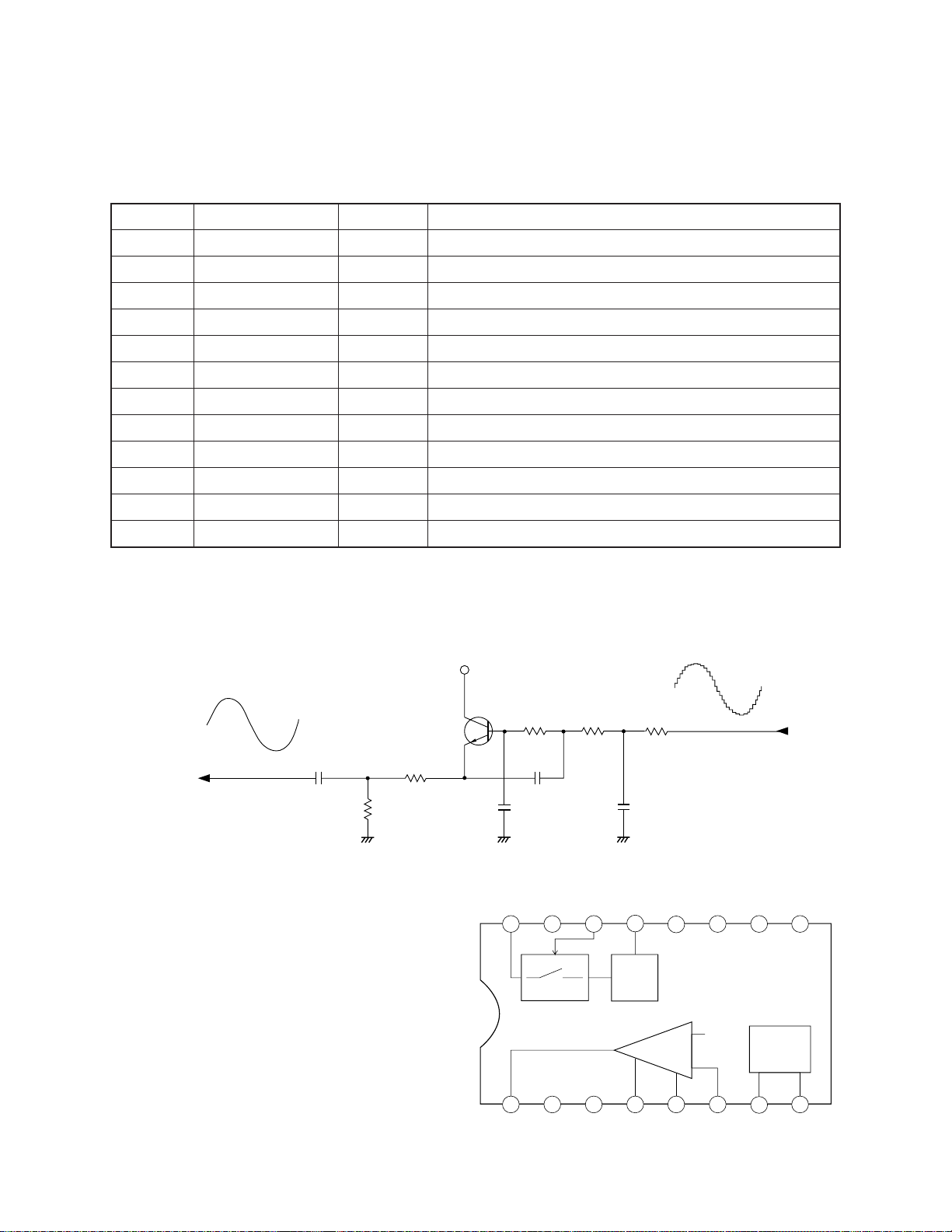
Filter Block
Since the sound signal from the CPU is a stepped waveform, the filter block is added to smooth the waveform.
AVDD
Q101
2SC1740SQ
C106
To power amp
R105
R104
AG
Amplifier/Voltage Regulator
(IC101: AN8053N)
The right figure shows the internal block of IC101.
R2106
C108
C107
AG
VCC NC CONT
16
15
POWER
R107
14 13
C109
AG
5V
VREG
5V REG
R108
From CPU
NCNC NC PRE GND
12 11
10
9
-
SP AMP
+
1
SPO NC SP GND PC-1 PC-2 SPI SPM VREF
4
32
6
5
— 4 —
7
VREF
8
Page 5
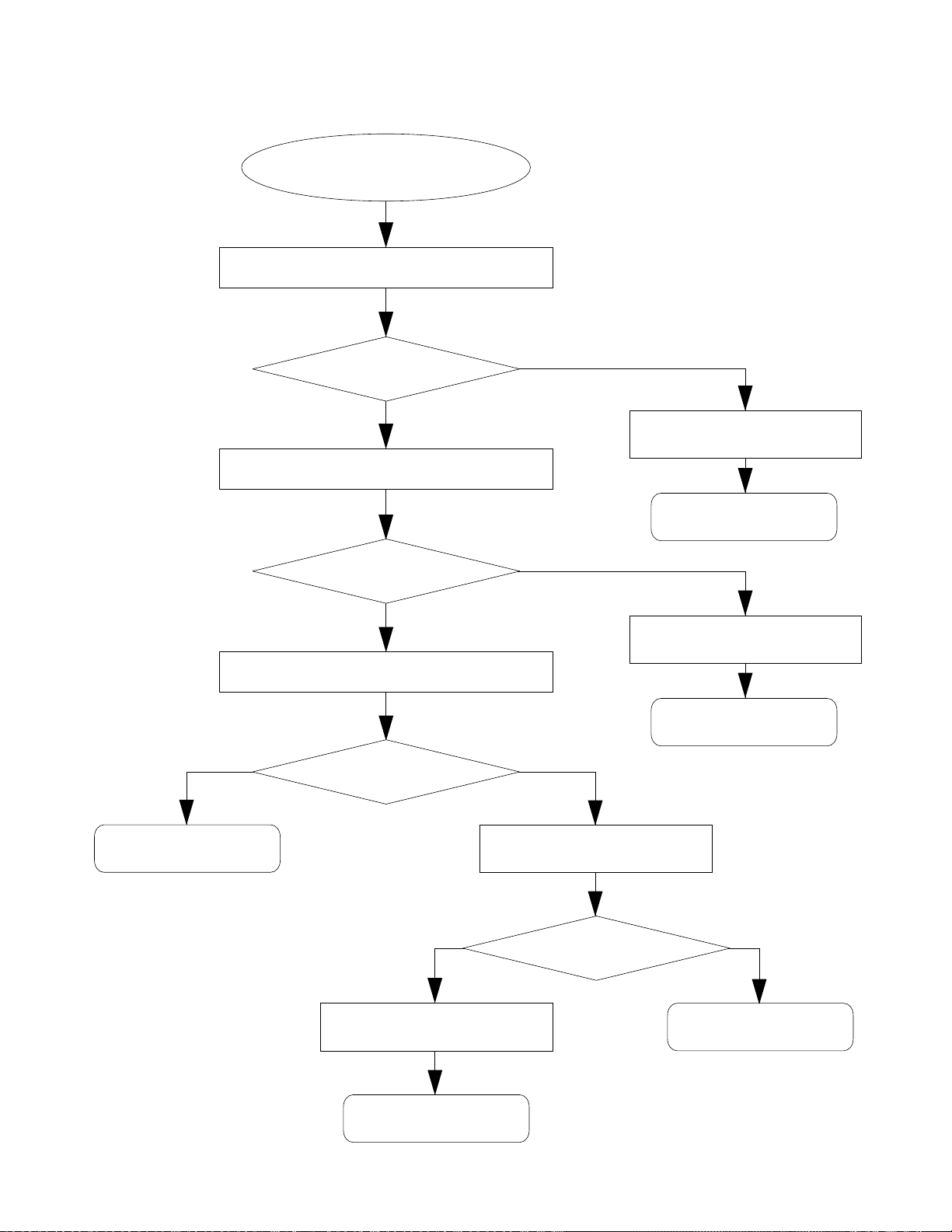
TROUBLESHOOTING
No power
Power indicator does not light up.
Connect an AC adapter into the power jack.
Does the keyboard work?
No
Measure voltage at pin 16 of IC AN8053N.
Is the voltage +6.8 V?
No
Check contact of the power jack.
No Yes
Is it OK?
Yes
Yes
Check contact at battery springs.
Replace D101.
Check contact of power switch.
Clean the switch contacts.
Replace the jack.
Yes
Check D102.
If D102 is defect,
replace it.
— 5 —
Check soldering at pins of the
power jack.
Is it OK?
No
Solder the pins.
Page 6

No sound
Measure voltage at pin 13 of IC AN8053N.
Yes No
Is the voltage +5 V ?
Measure voltage at pin 16 of IC AN8053N.
Is the voltage +6.8 V?
Measure voltage at pin 14 of IC AN8053N.
No
Follow flow chart
of No Power.
Turning power on, measure voltage
at pin 3 of LSI MSM6387-13.
Does the voltage raise
from 0 V to +5 V?
No
Clean contacts of the
power switch.
Replace IC AN8053N.
Yes
A
— 6 —
Is the voltage 0 V?
NoYes
Clean contacts of the
power switch.
Page 7

A
Measure voltage at pins 22 ~ 30 of LSI
MSM6387-13.
Yes No
Touch pin 5 of LSI MSM6387-13 with test
rod (+) of multimeter in resistance range,
connecting test rod (-) to ground.
Is a noise made?
Yes Yes
No
Replace LSI
MSM6387-13.
Touch pin 6 of IC AN8053N with test rod (+)
of multimeter in resistance range,
connecting test rod (-) to ground.
Is the voltage +0.3 V?
Replace LSI
MSM6387-13.
Does the keyboard work?
No
Replace ceramic
oscillator X101.
Does the keyboard work?
Yes
Is the noise made?
No
Check filter circuit around
Using a multimeter, check conductivity of
speaker at terminals on the main PCB.
Is it OK?
No
Replace speaker.
Yes
Q101.
Yes
Replace IC
AN8053N.
— 7 —
No
Replace transistor Q102.
Does the keyboard work?
No
Check the circuit around
Q102 and X101.
Yes
End
Page 8

MAJOR WAVEFORMS
1
1
CH1: 1V
Clock pulse COSI
1
1 Clock pulse COSI
MSM6387-13 pin 8
MSM6387-13 pin 8
50 ns
2
2
CH1
3
3
~
2 ms
CH1: 5 V–CH2: 5 V
2 Key scan signal KO0
Key scan signal KO0
2
MSM6387-13 pin 30
MSM6387-13 pin 30
3
3 Key scan signal KO1
Key scan signal KO1
MSM6387-13 pin 29
MSM6387-13 pin 29
–
2 ms
CH1
CH2
2 ms
4
4
5
5
CH1: 50 mV CH2: 50 mV
Sound signal output
4
4 Sound signal output
MSM6387-13 pin 5
MSM6387-13 pin 5
5
Filter output
5 Filter output
Emitter of Q201
Collector of Q101
~~
CH1
6
6
CH2
7
7
Tone : Flute (No.13)
Key : A3
Volume : Maximum
CH1: 50 mV CH2: 0.5 V
Power amp input
6
6 Power amp input
LA4598 pin 6
AN8053N pin 6
7
Power amp output
7 Power amp output
LA5498 pin 3
AN8053N pin 1
~~
CH1
CH2
— 8 —
Page 9

SCHEMATIC DIAGRAMS
— 9 —
Page 10

5
4
1
2
3
7
6
— 10 —
Page 11

Main PCB
PCB VIEW
1
3
2
4
5
6 7
— 11 —
Page 12

EXPLODED VIEW
3
R-1
4
5
6
1
8
7
R-2
11
10
9
12
2
13
— 12 —
Page 13

PARTS LIST
MA-100
Notes: This parts list does not include the cosmetic parts, which
parts are marked with item No. "R-X" in the exploded
view.
Contact our spare parts department if you need these
parts for refurbish.
1. Prices and specifications are subject to change without prior notice.
2. As for spare parts order and supply, refer to the
"GUIDEBOOK for Spare parts Supply", published
seperately.
3. The numbers in item column correspond to the same
numbers in drawing.
Page 14

FOB Japan
N Item Code No. Parts Name Specification Q N.R.Yen R
Unit Price
IC101 2114 3269 IC, Power Amp. AN8053N 1 A
LSI101 2011 2961 LSI, CPU MSM6387-13 1 A
Q101, 102 2220 1387 Transistor 2SC1740SQ-TP-T 2 B
D101 2390 1323 Diode RB100A-T32-T 1 B
D102 2390 0371 Diode DSK10B-BT-T 1 B
D103 2310 7848 Zener diode RD4. 3ESB2-T1-T 1 A
X101 2590 1897 Ceramic oscillator EFO-EN2175C4 1 B
J101 3501 3731 Power jack HEC2305-01-250 1 A
N 1 6925 0500 PCB ass'y, MA1M M240352*1 1 B
N 2 6925 0510 PCB ass'y, KY M240353*1 1 B
3 6921 5031 Slide knob M311859A-1 2 B
N 4 6925 0540 Button, Rubber M240278-1 1 B
5 6909 5890 Slide contact CSB-12D 2 B
N 6 3831 1029 Speaker 300RB03
N
N 8 6925 0560 Black key set, 13-key M140302-1 1 A
N 9 6925 0570 White key set, 10-key M140303-1 1 A
N 10 6925 0580 Black key set, 7-key M140304-1
N 11 6925 0590 Key contact rubber, 32-contact M240287-1 1 B
N12
7 6925 0550 White key set, 19-key M140301-1
6925 0600 Key contact rubber, 17-contact M240288-1
13 6906 7511
Battery cover
M312197A*3 1 B
1
1
1
1
B
A
A
B
Notes: N – New parts
R – Rank
— 13 —
Page 15

MA0400761A
 Loading...