

Page 1
M-300
INDEX
(with price)
M-300
ELECTRIONIC KEYBOARD
Page 2
CONTENTS
Specification ....................................................................2
Block Diagram .................................................................3
Circuit Description ........................................................... 3
PCB View and Major Waveforms ....................................5
Schematic Diagrams ....................................................... 6
Exploded View.................................................................8
Parts List .........................................................................9
SPECIFICATIONS
General
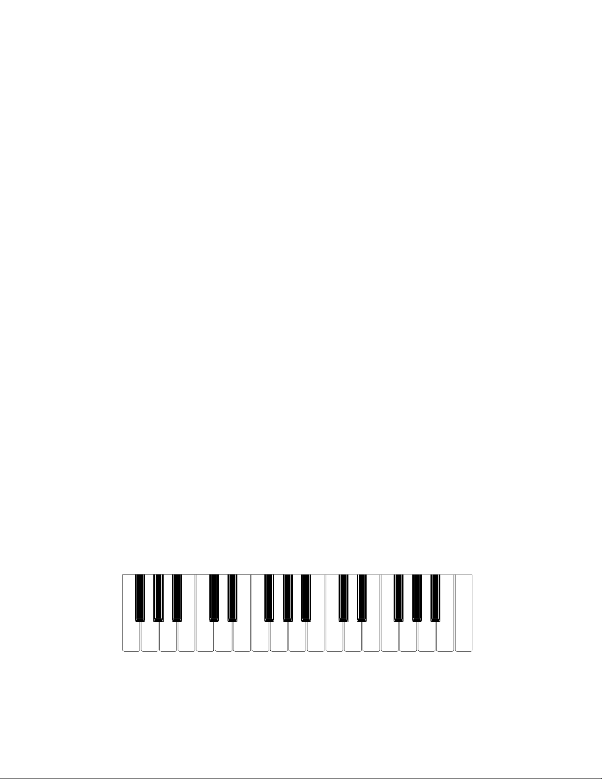
Number of Keys: 32
Polyphonic: 4-note
Preset Tones: 8
Preset Effects: 6
Preset Phrases: 4
Demonstration Tunes: 6
Function Dial: Magical sound dial
Built-In Speaker: 8 cm dia. 1.0 W Input Rating: 1 pce.
Power Source: 5 AA size dry batteries
Battery life: approx. 6 hours (SUM-3/R6P)
Power Consumption: 1.5 W
Dimensions (HWD): 58 x 439 x 205 mm
(2-1/4 x 17-1/4 x 8-1/16 inches)
Weight: 0.99 kg (2.2 lbs) including batteries
Electrical
Current Drain with 7.5 V DC:
NoSound Output 33 mA +/-20%
Maximum Volume 170 mA +/-20%
with keys G3, A3, B3 and C4 pressed
in Street Organ tone, Volume; Maximum
Speaker output level at 4 Ω load: 640 mV +/-20%
with key C4 pressed in Street Organ tone
Volume; Maximum
Minimum Operating Voltage: 5.0 V
Nomenclature of Keys
F#3 G#3 A#3 C#4 D#4 F#4 G#4 A#4 C#5 D#5 F#5 G#5 A#5
F3 G3 A3 B3 C4 D4 E4 F4 G4 A4 B4 C5 D5 E5 F5 G5 A5 B5 C6
— 2 —
Page 3
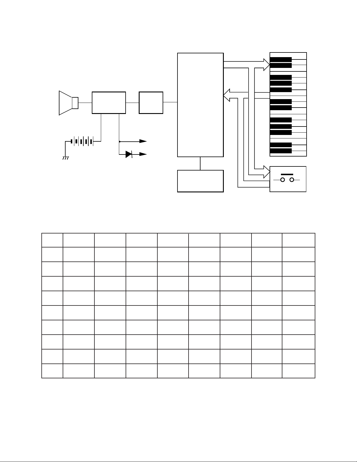
Speaker
Amplifier
AN8053N
IC101
BLOCK DIAGRAM
CPU
Filter
Q101
VDD
MSM6387-22
LSI101
KO0 ~ KO8
KI0 ~
KI7
AVDD
Oscillator
Q102, X101
Keyboard
Buttons
CIRCUIT DESCRIPTION
Key Matrix
KI0 KI1 KI2 KI3 KI4 KI5 KI6 KI7
KO0 F3 F#3 G3 G#3 A3 A#3 B3 C4
KO1 C#4 D4 D#4 E4 F4 F#4 G4 G#4
KO2 A4 A#4 B4 C5 C#5 D5 D#5 E5
KO3 F5 F#5 G5 G#5 A5 A#5 B5 C6
KO4 Music box Glass harp Piano Trumpet Flute Violin Woodbass
KO5 Train Car Quiz Cheer Animal
Volume
Down
Volume
Up
KO6 Stop Siren Horror Carnival Rap
Street
organ
Country
western
KO7 Dial SW-A Dial SW-B Dial WS-C
KO8 Song 1 Song 2 Song 3 Song 4 Song 5 Song 6
Song 1: Twinkle Twinkle Little Stars Song 4: Old MacDONALD Had a Farm
Song 2: Pop Goes the Weasel Song 5: Clap Your hands
Song 3: Lullaby (Brahms) Song 6: O Christmas Tree
— 3 —
Page 4
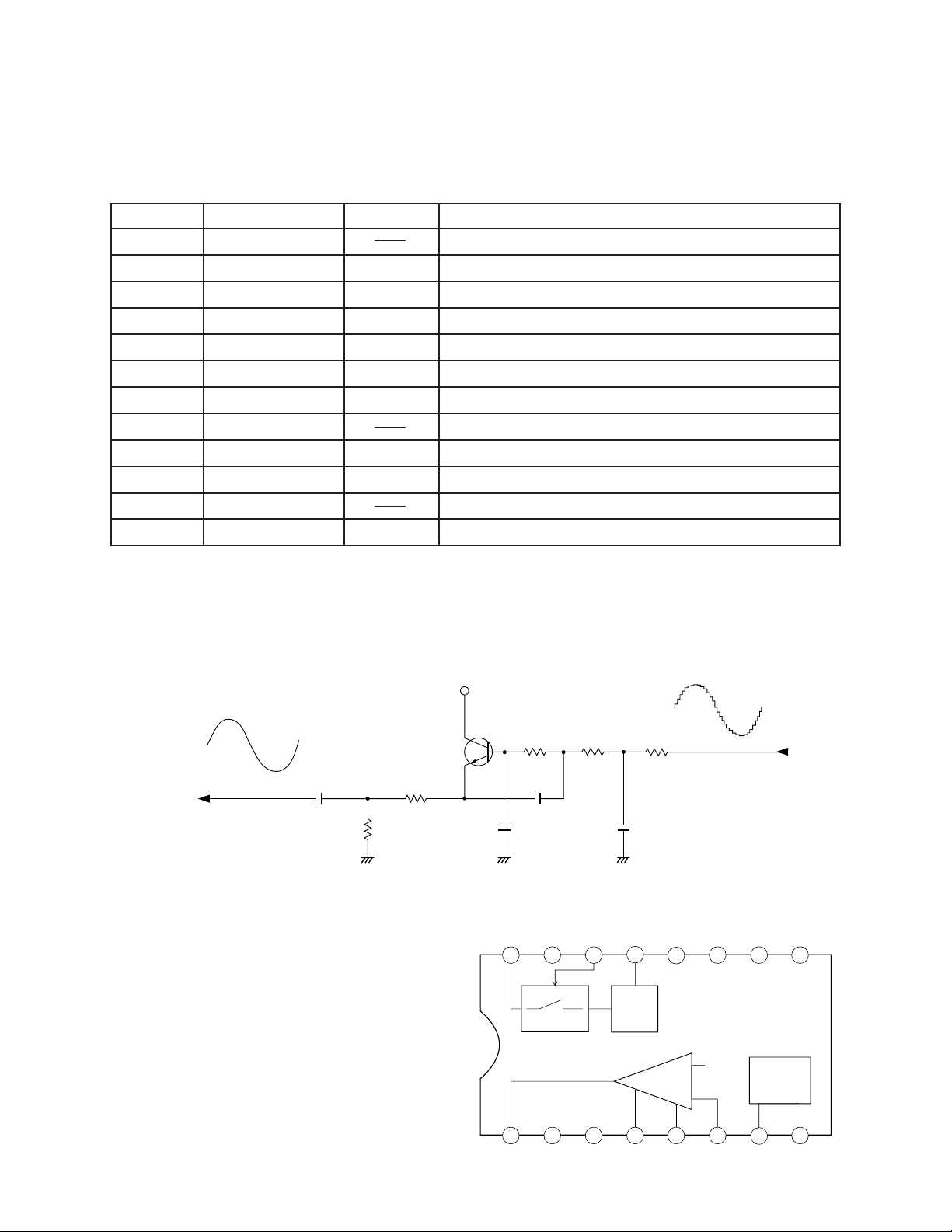
CPU (LSI101: MSM6387-22)
Containing a sound data ROM and a DAC (Digital to Analog Convertor), the CPU provides sound waveform in accodance with the pressed key and the selected tone.
The following table shows the pin functions of LSI101.
Pin No. Terminal In/ Out Function
1, 2 TEST1, TEST2 Not used. Connected to ground.
3 RESET In Power ON reset terminal. On: +5 V Off: 0 V
4 AVDD In +5 V sorce for the built-in DAC
5 OUT Out Sound waveform output
6 AGND In Ground (0 V) source for the built-in DAC
7 GND In Ground (0 V) source
8 COSI In 21.725 MHz clock pulse input
9 COSO Not used
10 VDD In +5 V source
11 ~ 18 KI0 ~ KI7 In Input terminals from keys and switches
19, 20 KO11, KO10 Not used
21 ~ 30 KO9 ~ KO0 Out Key and switch scan signal outputs
Filter Block
Since the sound signal from the CPU is a stepped waveform, the filter block is added to smooth the
waveform.
AVDD
Q101
2SC1740SQ
C106
To power amp
R105
R104
AG
Amplifier/Voltage Regulator
(IC101: AN8053N)
The right figure shows the internal block of IC101.
R2106
C108
C107
AG
VCC NC CONT
16
15
POWER
R107
14 13
C109
AG
5V
VREG
5V REG
R108
From CPU
NCNC NC PRE GND
12 11
10
9
-
SP AMP
+
1
SPO NC SP GND PC-1 PC-2 SPI SPM VREF
4
32
6
5
— 4 —
7
VREF
8
Page 5

PCB VIEW AND MAJOR WAVEFORMS
4
5
CH1 . 1V
CH2 . 1V
CH1
CH2
A 2ms
Px10 Px10
6 7
32
1
4
5
J101
R125
R126
R127
R115
R114
MC101
R113
R112
R111
757575
R123
R119
R118
R117
R116
R120
R121
R122
R124
C114
R130
5
R128
E
C111
X101
R129
C115
Q102
B
C117
C116
C110
5
JA
1JA
JCM547-MA1M A
1
75
13
5
LSI101
JCM547-MA1MA
13
5
R110
D104
D102
C104
R104
125
C105
C106
R105
C107
C109
R107
R106
C108
75
75
75
75
R108
5
B
E
Q101
IC101
C102
75
C103
No.
No. 3
D107D106D105
D112D111D110D109D108
R101
D101
L102
L101
PZ-R
R102
PS-Q
PS-BL
75
75
PZ-BK
LED101
D105
328
195
A 50ns
2
1
CH1
3
A 2ms
CH1
6
7
A 2ms
CH1
CH2
Px10
1V
˜
2 Key scan signal KO0
MSM6387-22 pin 30
3 Key scan signal KO1
MSM6387-22 pin 29
CH1
1 Clock pulse COSI
MSM6387-22 pin 9
Px10 Px10
CH1 5V CH2 5V
˜
4 Sound signal output
MSM6387-22 pin 5
5 Filter output
Emitter of Q101
˜
6 Power amp input
7 Power amp output
Px10 Px10
CH1 . 1V CH2 . 5V
˜
AN8053N pin 6
AN8053N pin 1
˜
Tone: Flute
Key: A4
Volume: Maximum
— 5 —
Page 6

SCHEMATIC DIAGRAMS
1
2.2
0.9
0.3
6
4.8
7
1.9
2.6
4
5
6.8
5.0
2
3
— 6 —
Page 7

— 7 —
Page 8

9
S-1
EXPLODED VIEW
10
a
11
12
8
14
6
5
4
3
1
7
S-1
15
13
16
S-1
17-1
S-1
2
S-2
S-3
17
17-2
18
— 8 —
Page 9

PARTS LIST
M-300
Notes: 1. Prices and specifications are subject to change with-
out prior notice.
2. As for spare parts order and supply, refer to the
"GUIDEBOOK for Spare parts Supply", published
seperately.
3. The numbers in item column correspond to the same
numbers in drawing.
— 1 —
Page 10

PARTS LIST
FOB Japan
N Item Code No. Parts Name Specification Q N.R.Yen R
Unit Price
Electrical Parts
1 6923 3400 PCB ass'y JCM547-MA1M M240093*1 1 1,650 B
LSI101 2011 9387 LSI MSM6387-22 1 440 A
IC101 2114 3269 IC AN8053N 1 110 A
Q101, Q102 2220 1387 Transistor 2SC1740SQ-TP-T 2 13 B
D101 2390 1323 Diode RB100A-T32-T 1 29 B
D102 2390 0371 Diode DSK10B-BT-T 1 11 B
D103 2310 7848 Zener diode RD4.3ESB2-T1-T 1 12 B
D104 ~ D112 2390 1344 Diode 1SS133T-77-T 9 3 B
J101 3501 3731 Power jack HEC2305-01-250 1 30 A
JA 3719 4438 Ribbon cable DF5H13080-8000M 1
L101, L102 3841 1057 Common mode coil CM05RB01 2 63 C
LED101 2370 1106 LED MPR3338S-B99 1 20 B
MC101 2845 0168 Module capacitor CNB8X101K 1
X101 2590 1897 Ceramic oscillator EFO-EN2175C4 1
2 6923 3410 PCB ass'y JCM574-KY1M M240094*1 1 450 B
D201 ~ D235 2390 1344 Diode 1SS133T-77-T 35 3 B
JB 3719 4431 Ribbon cable DF5H04105-80008000 1 15 C
2-1 4317 5440 Blank PCB JCM547-CN1M M240092-2 1 49 C
Mechanical Parts
N 3 6906 7540 Rubber button, 6-contact M340025-2 1 270 B
N 4 6923 0960 Rubber button, 9-contact M340024-2 2 290 B
5 6923 3430 Rubber button, 3-contact M340023-1 1 90 B
6 3831 0378 Speaker EAS-8P149BD 1 160 B
7 6909 5890 Slide contact CSB-12D 1 35 B
8 6906 5442 Slide knob M311360-2 1 14 A
9 6906 4374
N 10 6923 4380 Dial M240024-2 1 100 C
N 11 6923 4492 Upper case M240044B*3 1 450 C
12 6923 3061 Button M340026-1 3 33 C
13 6923 3460 Contact rubber M340027-1 1 40 B
14 6923 3520 Coupling M340028-1 1 35 C
15 6917 1080 Key contact rubber M310878-1 1 87 A
16 6917 3383 Key stopper M42611C-3 1 24 C
N 17 6923 4371 Lower case M240045A*3 1 410 C
17-1 6912 2630 Battery spring (-) M42382-1 1 14 B
17-2 6345 2238 Battery spring (+) A42606B-1 1 5 B
18 6906 7261 Battery cover M312197A*1 1 49 B
S-1
S-2 0009 4589 Screw 2.6 x 8 8 2 C
S-3 0009 5573 Screw 2.6 x 10 15 2 C
0009 2682
Key set, NM M411026D*1 1
Screw 2.6 x 8 16
26 C
58 C
60 B
210 A
2C
Notes: N – New parts
M – Minimum order/supply quantity
R – Rank
— 9 —
Page 11

Description of Capacitors
A general description of capacitors is shown in the following table.
The description consists of Type, Value, Rated Voltage and Tolerance.
When you need a capacitor, please find a substitution in your country by yourselves referring to the
description.
Ref. No of Capacitor Description
C102 Electrolytic, 100 µF, 16 V, ±20%
C103 Electrolytic, 470 µF, 10 V,±20%
C104, C105 Electrolytic, 22 µF, 10 V,±20%
C106 Semiconductive, 0.027 µF, 50 V, ±10%
C107 Semiconductive, 3300 pF, 50 V, ±10%
C108 Semiconductive, 0.047 µF, 50 V, ±10%
C109 Semiconductive, 0.018 µF, 50 V, ±10%
C110 Electrolytic, 1 µF, 50 V,±20%
C111 Electrolytic, 100 µF, 6.3 V,±20%
C113,C114 Ceramic, 0.1 µF, 50 V, +80/-20%
C115 Ceramic, 0.01 µF, 50 V, ±20%
C116 Ceramic, 8.2 pF, 50 V, ±10%
C117 Ceramic, 10 pF, 50 V, ±5%
Description of Resistors
A general description of resistors is shown in the following table.
The description consists of Type, Value, Rated Wattage and Tolerance.
When you need a resistor, please find a substitution in your country by yourselves referring to the description.
Note:
All resistors are carbon film, 1/5 watt, ±5% otherwise specified.
Ref. No of Resistor Description
R101 220 Ω
R102, R107, R108 1 kΩ
R104 3.9 KΩ
R105 1.5 KΩ
R106, R111 ~ R127 2.2 KΩ
R110 100 Ω
R128 1.2 Ω
R129 100 KΩ
R130 150 Ω
— 10 —
Page 12

8-11-10, Nishi-Shinjuku
Shinjuku-ku, Tokyo 160, Japan
Telephone: 03-3347-4926
May, 1995
 Loading...