

Page 1
M-200
INDEX
(without price)
M-200
ELECTRIONIC KEYBOARD
Page 2

CONTENTS
Specifications . . . . . . . . . . . . . . . . . . . . . . . . . . . . . . . . . . . . . . . . . . 1
Block Diagram . . . . . . . . . . . . . . . . . . . . . . . . . . . . . . . . . . . . . . . . . 2
Circuit Description . . . . . . . . . . . . . . . . . . . . . . . . . . . . . . . . . . . . . 3
Troubleshooting . . . . . . . . . . . . . . . . . . . . . . . . . . . . . . . . . . . . . . . 5
IC and Transistor Lead Identification . . . . . . . . . . . . . . . . . . . . . . . . 6
PCB View and Major Waveforms . . . . . . . . . . . . . . . . . . . . . . . . . . 7
Schematic Diagrams . . . . . . . . . . . . . . . . . . . . . . . . . . . . . . . . . . . . 8
Exploded View . . . . . . . . . . . . . . . . . . . . . . . . . . . . . . . . . . . . . . . . 10
Parts List . . . . . . . . . . . . . . . . . . . . . . . . . . . . . . . . . . . . . . . . . . . . 11
Page 3

SPECIFICATIONS
General
Number of Keys: 32
Polyphonic: 4-note
Preset Tones: 25
Tone Edit Variations: 4
Patterns: Auto-Rhythms: 8, including; 8-Beat, 16-Beat, Swing, Slow Rock, Shuffle,
March, Samba, Waltz
Accompaniments: 8, including; Rock, Pops, Jazz, Funk, House, Country,
Ratin, Classical
Funny Sounds: 8, including; Fanfare, Hpper, Computer Sound, Horror,
Child's Play, Orient, Jungle, Comedy
Demonstration Tunes: 10 tunes with Lesson Function
1. Twinkle Twinkle Little Star 6. Home, Sweet Home
2. Minuet (J.S. Bach) 7. Little Brown Jug
3. Oh! Susanna 8. The Skaters Waltz
4. Aura Lee 9. Jingle Bells
5. Lullaby (Brahms) 10. When The Saints Go Marching In
Built-In Speakers: 8.0 cm dia. 1.0 W Input Rating: 2 pcs.
Terminals: Output Jack [Output Impedance:100 Ω, Output Voltage: 2.1 V (rms) MAX]
AC Adapter Jack (DV 7.5 V)
Power Source: DC: 5 AA size dry batteries
Battery life: Approx. 6 hours (SUM-3/R6P)
AC: AC Adapter AD-1
Power Consumption: 1.6 W
Dimensions (HWD): 57 x 619 x 178 mm
(2-1/4 x 24-3/8 x 6 inches)
Weight: 1.1 kg (2.4 lbs) including batteries
Electrical
Current Drain with 7.5 V DC:
No Sound Output 28 mA ± 20%
Maximum Volume 90 mA ± 20%
with keys C4 and E4 pressed in Flute tone
Volume: Maximum, Accmpaniment: Latin,
Tempo: Maximum
Sound Pressure Level at 10 cm away from the speaker 100 dB ± 10 dB
with key C6 pressed in Clarinet, Volume: Maximum
Minimum Operating Voltage: 5.0 V
— 1 —
Page 4
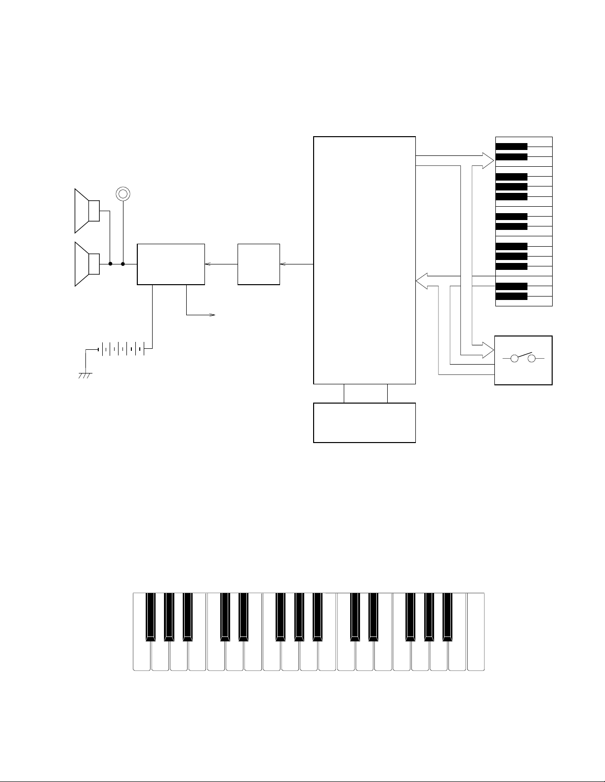
Output Jack
BLOCK DIAGRAM
KO0~KO6
CPU
Amplifier
AN8053N
IC1
Speakers
Nomenclature of Keys
VDD
Filter
T1
MSM6387-16
KI0~KI7
LSI1
Keyboard
Switches
Oscillator
X1
F#3 G#3 A#3 C#4 D#4 F#4 G#4 A#4 C#5 D#5 F#5 G#5 A#5
F3 G3 A3 B3 C4 D4 E4 F4 G4 A4 B4 C5 D5 E5 F5 G5 A5 B5 C6
— 2 —
Page 5
CIRCUIT DESCRIPTION
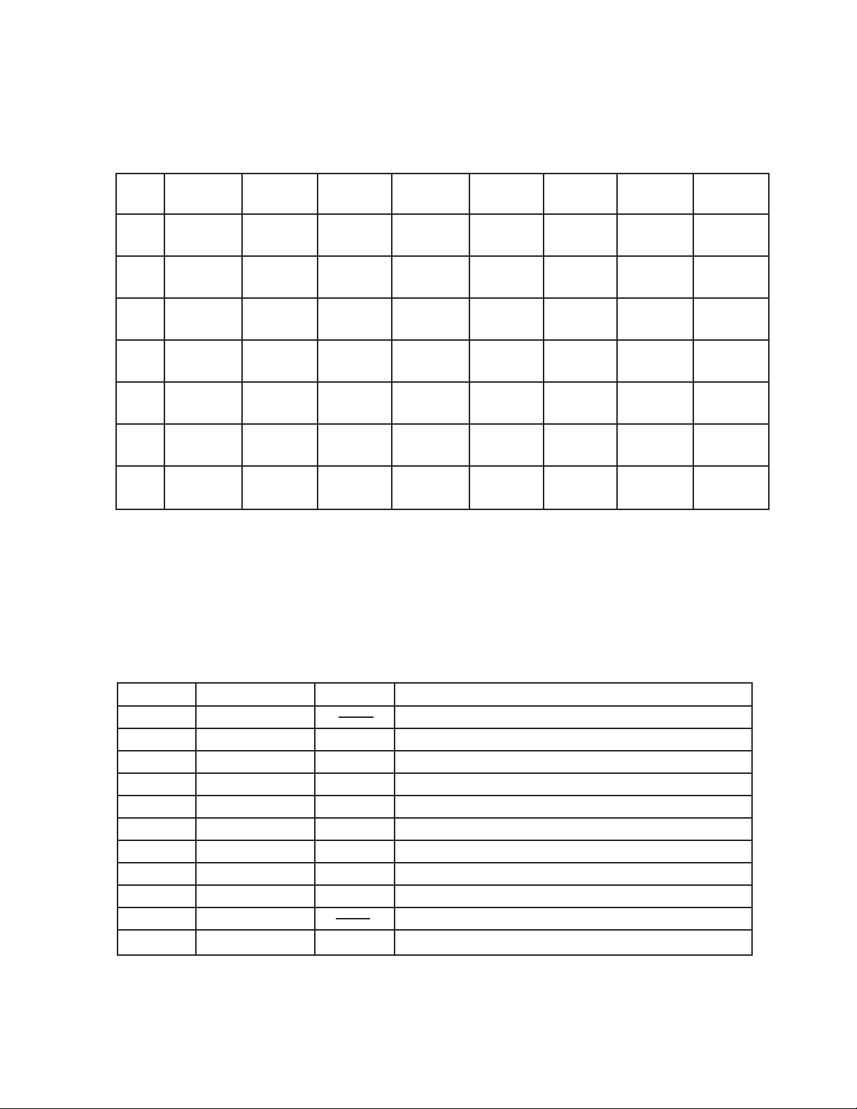
Key Matrix
KI0 KI1 KI2 KI3 KI4 KI5 KI6 KI7
KO0 F3 F#3 G3 G#3 A3 A#3 B3 C4
KO1 C#4 D4 D#4 E4 F4 F#4 G4 G#4
KO2 A4 A#4 B4 C5 C#5 D5 D#5 E5
KO3 F5 F#5 G5 G#5 A5 A#5 B5 C6
KO4 Keyboard Wind String Synth S.E. Tone Edit
KO5 Rhythm Accomp. Stop
KO6 Lesson MelodyOff Demo
CPU (LSI1: MSM6387-16)
Containing a sound data ROM and a DAC (Digital to Analog Convertor), the CPU provides sound waveform in accordance with the pressed key and the selected tone.
The following table shows the pin functions of LSI1.
Pin No. Terminal In/ Out Function
1, 2 TEST1, TEST2 Not used. Connected to ground.
3 RESET In Power ON reset input. On: +6 V Off: 0 V
4 AVDD In +5 V sorce for the built-in DAC
5 OUT Out Sound waveform output
6 AGND In Ground (0 V) source for the built-in DAC
7 GND In Ground (0 V) source
8, 9 COSI, COSO In/Out 21.725 MHz clock pulse input/output
10 VDD In +5 V source
11 ~ 18 KI0 ~ KI7 In Input terminal from keys and switches
19 ~ 22 KO11 ~ KO8 Not used.
23 ~ 30 KO7 ~ KO0 Out Key and switch scan signal output
Funny
Accomp.
Tempo
Up
Volume
Up
Tempo
Down
Volume
Down
— 3 —
Page 6

Filter Block
Since the sound signal from the CPU is a stepped waveform, the filter block is added to smooth the
waveform.
AVDD
T1
2SC1740SQ
R6
R7 R8
C5
To Amplifier
R5
AG
R11
C9
AG
From CPU
C10
C11
AG
Amplifier/Voltage Regulator (IC1: AN8053N)
Consisting of an amplifier and a voltage regulator, AN8053N amplifies the sound signal from the CPU and
also provides the CPU +5V source.
The following figure shows the internal block of IC1.
5V
VCC NC CONT
16
15
VREG
14 13
NCNC NC PRE GND
12 11
10
9
5V REG
POWER
-
SP AMP
+
1
SPO NC SP GND PC-1 PC-2 SPI SPM VREF
32
4
5
6
7
VREF
8
— 4 —
Page 7

TROUBLESHOOTING
Nature of Trouble
No sound at all
Certain key(s) or
switch(es) do(es) not
work.
Faulty Block
Power amp.
(IC1: AN8053N)
Power Switch
CPU
(LSI1: MSM6387-16)
Oscillator (X1)
Key or Switch Contact
Open Circuit on KO or KI
Lines
Checkpoint
Pin 13 should have +5V.
An amplified waveform should be observed at pin
1.
Voltage at pin 3 of the CPU should be raised from
0V to +5V when the power switch is turned on.
Switch contact.
Pins 24 ~ 30 should provide pulses.
Pin 5 should provide a sound waveform when a
key is pressed.
Pins 8 and 9 of the CPU should receive an
oscillation signal.
— 5 —
Page 8

IC AND TRANSISTOR LEAD IDENTIFICATION
LSI1: MSM6387-16
30292824272625
KO0
KO1
KO2
KO3
KO4
KO5
TEST2
TEST1
RESET
AVDD
OUT
AGND
1
2
374
5
6
IC1: AN8053N
16
15
14
NC
VCC
CONT
23222120191817
KO6
KO7
KO8
KO9
KO10
GND
COSI
COSO
VDD
KI0
8
9
1011121314
13
12
11
10
NC
NC
NC
VREG
KI7
KO11
KI1
KI2
9
PR GND
KI6
KI3
16
KI5
KI4
15
SPONCSPG
1
2
3
T1: 2SC1740SQ
E C B
PC-1
4
— 6 —
PC-2
5
SPI
6
SPM
7
VREF
8
Page 9

Main PCB M3546-MA1M (Top View)
4
5
1 3 2
PCB VIEW & MAJOR WAVEFORMS
1
Clock pulse COSO
1
MSM6387-16 Pin 9
2
5
4
3
Key scan signal KO0
2
MSM6387-16 Pin 30
Key scan signal KO1
3
MSM6387-16 Pin 29
— 7 —
Sound output
4 Power Amp. output
MSM6387-16 Pin 5
Tone : Piano
Key : G4
5
AN8053N Pin 1
Tone : Piano
Key : G4
Volume : Max.
Page 10

PCB M3546-MA1M
SCHEMATIC DIAGRAM
1
4
5.2
4.7
2.5
0.0
0.0
~
4.9
0.0
0.0
0.0
~
0.0
2.2
0.6
0.5
0.5
2.0
0.0
4.7
1.9
4.5
0.5
~
0.5
5
3.1
4.1
0.0
4.0
4.1
9.1
0.0
5.2
5.2
0.0
3
2
— 8 —
Page 11

KY1M KEYBOARD PCB
— 9 —
Page 12

EXPLODED VIEW
11
9
8
6
10
12
3
4
7
1
13-1
13-2
2
16
13
17
5
15
— 10 —
14
Page 13

PARTS LIST
M-200
Notes: 1. Prices and specifications are subject to change with-
out prior notice.
2. As for spare parts order and supply, refer to the
"GUIDEBOOK for Spare parts Supply", published
seperately.
3. The numbers in item column correspond to the same
numbers in drawing.
Page 14

FOB Japan
N Item Code No. Parts Name Specification Q M N.R.Yen R *
Unit Price
Electrical Parts
LSI1 2011 4767 LSI MSM6387-16SS-106 1 1 A E
IC1 2114 3269 Monolithic IC AN8053N 1 1 A B
T1 2252 0497 Transistor 2SC3199Y-AT-T 1 20 B A
D1 2390 0371 Diode DSK10B-BT-T 1 10 B A
D2 2390 1316 Diode SB10-04A3-BT-T 1 5 B A
D4~12,51~82 2390 1589 Diode MA165P-(TA5)-T 42 20 C A
X1 2590 0742 Ceramic oscillator EFO-GC2175C3 1 1 B B
R3,7,8 2606 1141 Carbon film resistor R-20-1K-J-T23-T 3 20 C A
R1,2,9,10 2606 1169 Carbon film resistor R-20-100-J-T23-T 4 20 C A
R6 2606 1288 Carbon film resistor R-20-2.2K-J-T23-T 1 20 C A
R5 2606 1365 Carbon film resistor R-20-3.9K-J-T23-T 1 20 C A
R11 2606 1484 Carbon film resistor R-20-820-J-T23-T 1 20 C A
R4 2606 1554 Carbon film resistor R-20-120K-J-T23-T 1 20 C A
C1 2802 9777 Electrolytic capacitor 16RE3-470-T20-T 1 20 C A
C8 2805 3061 Electrolytic capacitor 6.3RE2-220-T2-T 1 10 C A
C3/4 2805 3134 Electrolytic capacitor 10RE2-22-T2-T 2 20 C A
C6 2807 1023 Electrolytic capacitor 50RE2-1-T2-T 1 10 C A
C7 2807 1091 Electrolytic capacitor 6.3RE2-100-T2-T 1 10 C A
C2 2807 1710 Electrolytic capacitor 16RE3-220-T2-T 1 20 C A
C9 2813 0651 Semiconductive capacitor RT-C40TKYR332K-T 1 20 C A
C5 2813 1932 Semiconductive capacitor RT-C50TKYR223K-T 1 20 C A
C10 2813 1939 Semiconductive capacitor RT-B70TKYR473K-T 1 20 C A
C12/13 2813 2093 Semiconductive capacitor TR-B50TKYR103K-T 2 20 C A
C11 2813 2415 Semiconductive capacitor RT-B50TKYR153K-T 1 20 C A
FB1~4 2845 3220 Ferrite beads EXC-ELDR35V-T 4 20 C A
J1 3501 3731 DC jack HEC2305-01-250 1 5 A A
J2 3612 0711 Miniature jack YKB21-5101 1 1 A B
3719 3990 Ribbon cable M546A DF5H12065-80008000 1 20 C A
L1/2 3841 0910 Coil FL5R1R0PNA 2 5 C A
4317 3550 Blank PCB M3546-MA1M M111579-1 1 1 C B
4317 3560 Blank PCB M3546-KY1M M111579-2 1 1 C B
1 6921 6390 PCB ass'y M3546-MA,KY M111578*1 1 1 B P
Mechanical Parts
2 3831 0385 Speaker EAS-8P149AD 1 2 C B
3 6909 7380 SL contact 9D CSB-09D 1 10 B A
4 6917 1471 Key contact rubber M210670A-1 1 5 B B
5 6917 1511 White key set M110550A-1 1 1 A B
6 6917 1522 Black key set M110551B-1 1 5 A B
7 6917 4510 Stopper 216 M411074-1 1 10 C A
8 6921 6480 Slide knob 601 M311859-2 1 10 B A
N 9 6922 7180 Upper case sub ass'y M211568*6 1 1 C E
10 6917 1491 Upper key stopper M310881A-1 1 10 C A
11 6917 1500 Key stopper 216 M411040-1 2 10 C A
N 12 6922 6230 Rubber button M546 M211555-3 1 1 C C
N 13 6906 6965 Lower case sub ass'y M211570E*5 1 1 C E
13-1 6345 2238 Battery spring (+) A-G55 A42606B-1 1 20 C A
13-2 6912 2630 Battery spring (-) 120 M42382-1 1 10 C A
14 6921 6500 Battery cover 546 M311914-1 1 5 B A
N 15 6922 9490 Rating label M411126-17 1 10 C A
16 0009 2682 Screw 2.6 x 8 ZMC-3 21 20 C A
17 0009 5573 Screw 2.6 x 10 ZMC-3 15 20 C A
Notes: N – New parts
M – Minimum order/supply quantity
R – Rank
— 11 —
Page 15

8-11-10, Nishi-Shinjuku
Shinjuku-ku, Tokyo 160, Japan
Telephone: 03-3347-4926
Aug, 1994
 Loading...