

Page 1
M-100
INDEX
(without price)
M-100
ELECTRIONIC KEYBOARD
Page 2

CONTENTS
Specifications . . . . . . . . . . . . . . . . . . . . . . . . . . . . . . . . . . . . . . . . . . 1
Block Diagram . . . . . . . . . . . . . . . . . . . . . . . . . . . . . . . . . . . . . . . . . 2
Circuit Description . . . . . . . . . . . . . . . . . . . . . . . . . . . . . . . . . . . . . 3
Troubleshooting . . . . . . . . . . . . . . . . . . . . . . . . . . . . . . . . . . . . . . . 4
PCB View and Major Waveforms . . . . . . . . . . . . . . . . . . . . . . . . . . 5
Schematic Diagrams . . . . . . . . . . . . . . . . . . . . . . . . . . . . . . . . . . . . 6
IC Lead Identification . . . . . . . . . . . . . . . . . . . . . . . . . . . . . . . . . . . 7
Exploded View . . . . . . . . . . . . . . . . . . . . . . . . . . . . . . . . . . . . . . . . . 8
Parts List . . . . . . . . . . . . . . . . . . . . . . . . . . . . . . . . . . . . . . . . . . . . . 9
Page 3

SPECIFICATIONS
General
Number of Keys: 32
Polyphonic: 2-note
Preset Tones: 25
Tone Edit Variations: 4
Patterns: Auto-Rhythms: 8, including; 8-Beat, 16-Beat, Swing, Slow Rock, Shuffle,
March, Samba, Waltz
Accompaniments: 8, including; Rock, Pops, Jazz, Funk, House, Country,
Ratin, Classical
Funny Sounds: 8, including; Fanfare, Hpper, Computer Sound, Horror,
Child's Play, Orient, Jungle, Comedy
Demonstration Tune: Twinkle Twinkle Little Star
Oh! Susanna
Lullaby (Brahms)
Little Brown Jug
Jingle Bells
Built-In Speaker: 6.5 cm dia. 1.0 W Input Rating: 1 pce.
Terminals: Output Jack [Output Impedance:120 Ω, Output Voltage: 1.6 V (rms) MAX]
AC Adapter Jack (DV 7.5 V)
Power Source: DC: 4 AA size dry batteries
Battery life: Approx. 5 hours (SUM-3/R6P)
AC: AC Adapter AD-1
Power Consumption: 0.6 W
Dimensions (HWD): 41 x 382 x 125 mm
(1-5/8 x 15 x 5 inches)
Weight: 0.5 kg (1.1 lbs) including batteries
Electrical
Current Drain with 7.5 V DC:
No Sound Output 28 mA ± 20%
Maximum Volume 90 mA ± 20%
with keys C4 and E4 pressed in Flute tone
Volume: Maximum, Accmpaniment: Latin,
Tempo: Maximum
Sound Pressure Level at 10 cm away from the speaker 100 dB ± 10 dB
with key C6 pressed in Clarinet, Volume: Maximum
Minimum Operating Voltage: 5.0 V
— 1 —
Page 4
Output Jack
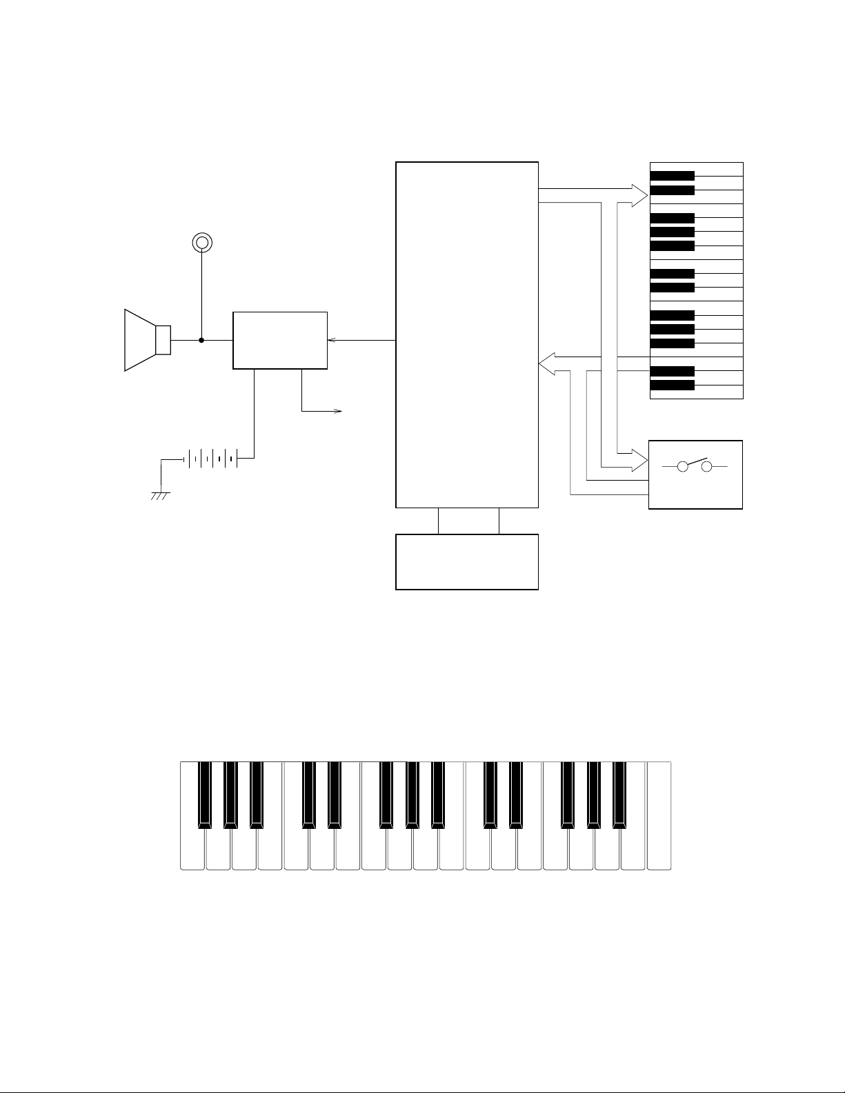
BLOCK DIAGRAM
KO0~KO6
CPU
Speaker
Nomenclature of Keys
Amplifier
AN8053N
IC1
VDD
MSM6387-16
KI0~KI7
LSI1
Keyboard
Switches
Oscillator
X1
F#3 G#3 A#3 C#4 D#4 F#4 G#4 A#4 C#5 D#5 F#5 G#5 A#5
F3 G3 A3 B3 C4 D4 E4 F4 G4 A4 B4 C5 D5 E5 F5 G5 A5 B5 C6
— 2 —
Page 5

CIRCUIT DESCRIPTION
Key Matrix
KI0 KI1 KI2 KI3 KI4 KI5 KI6 KI7
KO0 F3 F#3 G3 G#3 A3 A#3 B3 C4
KO1 C#4 D4 D#4 E4 F4 F#4 G4 G#4
KO2 A4 A#4 B4 C5 C#5 D5 D#5 E5
KO3 F5 F#5 G5 G#5 A5 A#5 B5 C6
KO4 Keyboard Wind String Synth S.E. Tone Edit
KO5 Rhythm Accomp. Stop
KO6 Demo
CPU (LSI1: MSM6387-16)
Containing a sound data ROM and a DAC (Digital to Analog Convertor), the CPU provides sound waveform in accordance with the pressed key and the selected tone.
The following table shows the pin functions of LSI1.
Pin No. Terminal In/ Out Function
1, 2 TEST1, TEST2 Not used. Connected to ground.
3 RESET In Power ON reset input. On: +6 V Off: 0 V
4 AVDD In +5 V sorce for the built-in DAC
5 OUT Out Sound waveform output
6 AGND In Ground (0 V) source for the built-in DAC
7 GND In Ground (0 V) source
8, 9 COSI, COSO In/Out 21.725 MHz clock pulse input/output
10 VDD In +5 V source
11 ~ 18 KI0 ~ KI7 In Input terminal from keys and switches
19 ~ 23 KO11 ~ KO7 Not used.
24 ~ 30 KO6 ~ KO0 Out Key and switch scan signal output
Funny
Accomp.
Tempo
Up
Volume
Up
Tempo
Down
Volume
Down
— 3 —
Page 6

Amplifier/Voltage Regulator (IC1: AN8053N)
Consisting of an amplifier and a voltage regulator, AN8053N amplifies the sound signal from the CPU and
also provides the CPU +5V source.
The following figure shows the internal block of IC1.
5V
VCC NC CONT
16
15
POWER
VREG
14 13
5V REG
12 11
SP AMP
NCNC NC PRE GND
10
-
+
9
VREF
Nature of Trouble F
No sound at all
1
SPO NC SP GND PC-1 PC-2 SPI SPM VREF
32
4
5
6
7
8
TROUBLESHOOTING
Faulty Block
Power amp.
(IC1: AN8053N)
Power Switch
CPU
(LSI1: MSM6387-16)
Oscillator (X1)
Pin 13 should have +5V.
An amplified waveform should be observed at pin
1.
Voltage at pin 3 of the CPU should be raised from
0 V to +5 V when the power switch is turned on.
Switch contact.
Pins 24 ~ 30 should provide pulses.
Pin 5 should provide a sound waveform when a
key is pressed.
Pins 8 and 9 of the CPU should receive an
oscillation signal.
Checkpoint
Certain key(s) or
switch(es) do(es) not
work.
Key or Switch Contact
Open Circuit on KO or KI
Lines
— 4 —
Page 7

Top View
1
45
3
2
PCB VIEW & MAJOR WAVEFORMS
2
5
1
4
3
Clock pulse COSO
1
MSM6387-16 Pin 9
Key scan signal KO0
2
MSM6387-16 Pin 30
Key scan signal KO1
3
MSM6387-16 Pin 29
4 Power Amp. output
Sound output
MSM6387-16 Pin 5
Tone : Piano
Key : G4
5
AN8053N Pin 1
Tone : Piano
Key : G4
Volume : Max.
— 5 —
Page 8

1
5
0.0
4
2
3
0.0
5.2
4.8
2.5
0.0
0.0
2.2
2.2
4.9
0.0
0.0
0.0
0.0
0.0
0.0
0.0
0.0
0.5
0.5
0.5
0.5
0.5
0.5
0.5
4.0
0.0
3.9
3.1
4.0
9.0
0.0
5.2
5.2
0.0
PCB M3541-MA1M
SCHEMATIC DIAGRAM
— 6 —
Page 9

IC LEAD IDENTIFICATION
LSI1: MSM6387-03
30292824272625
KO0
KO1
KO2
KO3
KO4
KO5
TEST2
TEST1
RESET
AVDD
OUT
AGND
1
2
374
5
6
IC1: AN8053N
16
15
14
23222120191817
KO6
KO7
KO8
KO9
KO10
GND
COSI
COSO
VDD
KI0
8
9
1011121314
13
12
11
10
KI7
KO11
KI1
KI2
9
KI6
KI3
16
KI5
KI4
15
NC
VCC
SPONCSPG
1
CONT
2
3
VREG
PC-1
4
5
NC
PC-2
NC
SPI
6
NC
SPM
7
PR GND
VREF
8
— 7 —
Page 10

EXPLODED VIEW
11
7
12
4
8
3
2
5
6
1
13
9
13
10
— 8 —
Page 11

PARTS LIST
M-100
Notes: 1. Prices and specifications are subject to change with-
out prior notice.
2. As for spare parts order and supply, refer to the
"GUIDEBOOK for Spare parts Supply", published
seperately.
3. The numbers in item column correspond to the same
numbers in drawing.
Page 12

FOB Japan
N Item Code No. Parts Name Specification Q M N.R.Yen R *
Unit Price
Electrical Parts
LSI1 2011 4767 LSI MSM6387-16SS-106 1 1 A E
IC1 2114 3269 Monolithic IC AN8053N 1 1 A B
D1 2390 0371 Diode DSK10B-BT-T 1 10 B A
D2 2390 1316 Diode SB10-04A3-BT-T 1 5 B A
D3 2390 1344 Diode 1SS133T-77-T 1 20 C A
X1 2590 0742 Ceramic oscillator EFO-GC2175C3 1 1 A B
R3 2606 1141 Carbon film resistor R-20-1K-J-T23-T 1 20 C A
R7 2606 1169 Carbon film resistor R-20-100-J-T23-T 1 20 C A
R5 2606 1239 Carbon film resistor R-20-8.2K-J-T23-T 1 20 C A
R6 2606 1274 Carbon film resistor R-20-1.5K-J-T23-T 1 20 C A
R4 2606 1554 Carbon film resistor R-20-120K-J-T23-T 1 20 C A
R1/2 2606 1617 Carbon film resistor R-20-120-J-T23-T 2 20 C A
C1 2802 9777 Electrolytic capacitor 16RE3-470-T20-T 1 20 C A
C8 2805 3061 Electrolytic capacitor 6.3RE2-220-T2-T 1 10 C A
C3/4 2805 3134 Electrolytic capacitor 10RE2-22-T2-T 2 20 C A
C6 2807 1023 Electrolytic capacitor 50RE2-1-T2-T 1 10 C A
C7 2807 1091 Electrolytic capacitor 6.3RE2-100-T2-T 1 10 C A
C2 2807 1710 Electrolytic capacitor 16RE3-220-T2-T 1 20 C A
C5 2813 2254 Semiconductive capacitor DD405SR333K16-T 1 20 C A
FB1~3 2845 3220 Ferrite beads EXC-ELDR35V-T 3 20 C A
J1 3501 3731 DC jack HEC2305-01-250 1 5 A A
J2 3501 4382 Jack HSJ2000-01-010 1 5 C B
4317 3570 Blank PCB M3541-MA1M M111577-1 1 1 C B
6917 1762 B spring (+) A210 M410913B-1 1 10 B A
6921 6210 B spring (-) 700B M412171-1 1 10 B A
1 6921 6710 PCB ass'y M3541-MA1M M211608*1 1 1 B L
Mechanical Parts
2 3831 0644 Speaker 65G08BFC 1 1 B B
3 6909 7380 SL contact 9D CSB-09D 1 10 B A
4 6917 1571 White key set M210 M210610A-1 1 5 A B
5 6917 1580 Black key set M210 M210609-1 1 10 A A
6 6917 1591 Contact rubber M210 M210605A-1 1 5 B B
7 6921 6790 Slide knob 541 M311913-1 1 10 B A
N 8 6922 7680 Rubber button 541A M311911-2 1 1 C B
9 6921 6810 Lower case M111516-1 1 1 C B
10 6921 6820 Battery cover M311910-1 1 5 B A
N 11 6922 7750 Upper case M111515-6 1 1 C C
N 12 6922 7520 Rubber button 541B M311912-3 1 1 C B
13 5150 1101 Screw P-Tight 2.3 x 8 ZMC 10 50 C A
N 6922 9480 Rating label M411126-16 1 10 C A
Notes: N – New parts
M – Minimum order/supply quantity
R – Rank
— 9 —
Page 13

8-11-10, Nishi-Shinjuku
Shinjuku-ku, Tokyo 160, Japan
Telephone: 03-3347-4926
Aug, 1994
 Loading...