

Page 1

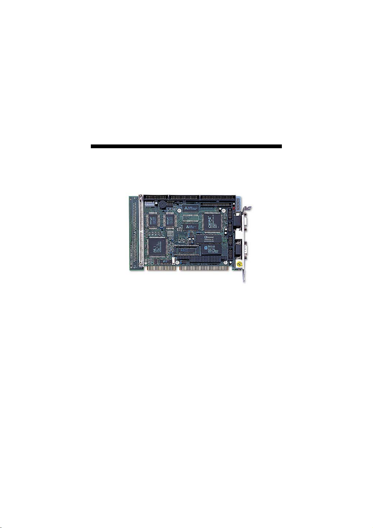
HS-3000/4M
386 ISA Bus SBC
CRT/Panel•RS-232/422/485•4 COM•
•
•PC/104•DOC•WDT•Single +5V•
ISA Bus Industrial Single Board Computer
Page 2

C
o
p
y
r
i
g
h
t
D
i
s
c
l
a
i
m
e
r
s
C
o
p
y
r
i
g
h
t
D
i
s
c
l
a
i
C
o
p
y
r
i
g
h
t
D
i
The accuracy of contents in this manual has passed thorough checking and review
before publishing. BOSER Technology Co., Ltd., the manufacturer and publisher, is
not liable for any infringements of patents or other rights resulting from its use. The
manufacturer will not be responsible for any direct, indirect, special, incidental
or consequential damages arising from the use of this product or
documentation, even if advised of the possibility of such damage(s).
This manual is copyrighted and BOSER Technology Co., Ltd. reserves all
documentation rights. Unauthorized reproduction, transmission, translation,
and storage of any form and means (i.e.,
recording) of this document, in whole or partly, is prohibited, unless granted
permission by BOSER Technology Co., Ltd.
BOSER Technology Co., Ltd. reserves the right to change or improve the
contents of this document without due notice.
assumes no responsibility for any errors or omissions that may appear in this
manual, nor does it make any commitment to update the information contained
herein.
T
r
a
d
e
m
a
r
k
s
T
r
a
d
e
m
T
r
a
d
e
m
BOSER is a registered trademark of BOSER Technology Co., Ltd.
ISB is a registered trademark of BOSER Technology Co., Ltd.
Intel is a registered trademark of Intel Corporation.
Award is a registered trademark of Award Software, Inc.
AMI is a registered trademark of AMI Software, Inc.
All other trademarks, products and or product names mentioned herein are
mentioned for identification purposes only, and may be trademarks and/or
registered trademarks of their respective companies or owners.
a
r
k
s
a
r
k
s
m
s
c
l
a
i
m
e
e
r
s
r
s
electronic, mechanical, photocopying,
BOSER Technology Co., Ltd.
© Copyright 2004 BOSER Technology Co., Ltd.
All Rights Reserved.
Edition 1.6 August 05, 2004
Page 3

Table of Contents
Chapter 1 General Description..............................1
1.1 Major Features.................................................................. 2
1.2 Specifications ................................................................... 3
1.3 Board Dimensions............................................................ 4
Chapter 2 Unpacking .............................................5
2.1 Opening the Delivery Package........................................ 5
2.2 Inspection.......................................................................... 5
Chapter 3 Hardware Installation ..........................7
3.1 Before Installation ............................................................ 7
3.2 Board Layout .................................................................... 8
3.3 Jumper List ....................................................................... 9
3.4 Connector List .................................................................. 9
3.5 DiskOnChip Address Setting ..................................... 10
3.6 Watchdog Timer ............................................................. 10
3.7 VGA Controller................................................................ 12
3.8 Serial Port Connectors .................................................. 17
3.9 Keyboard & Mouse Connector...................................... 18
3.10 Speaker Connector ........................................................ 19
3.11 PCI E-IDE Drive Connector............................................ 20
3.12 Parallel Connector.......................................................... 21
3.13 Power and LED Connectors .......................................... 21
3.14 Floppy Disk Drive Connector ........................................ 22
3.15 Flash ROM Type ............................................................. 23
3.16 System Memory.............................................................. 23
3.17 PC/104 Bus Connection................................................. 23
Page 4

Chapter 4 AMI BIOS Setup.................................27
4.1 Starting Setup ................................................................. 27
4.2 Using Setup..................................................................... 28
4.3 Main Menu ....................................................................... 29
4.4 Standard CMOS Setup ................................................... 30
4.5 Advanced CMOS Setup ................................................. 31
4.6 Advanced Chipset Setup ............................................... 32
4.7 PCI / Plug And Play Setup ............................................. 33
4.8 Peripheral Setup............................................................. 34
4.9 Auto-Detect Hard Disks ................................................. 35
4.10 Change Supervisor/User Password ............................. 36
4.11 Auto Configuration with Optimal Settings................... 37
4.12 Auto Configuration with Fail Safe Settings ................. 38
4.13 Save Settings and Exit................................................... 39
4.14 Exit Without Saving........................................................ 40
Page 5

S
a
f
e
t
y
I
n
s
t
r
u
c
t
i
o
n
s
S
a
f
e
t
y
I
n
s
t
r
u
c
S
a
f
e
t
y
I
n
s
Integrated circuits on computer boards are sensitive to static electricity.
To avoid damaging chips from electrostatic discharge, observe the
following precautions:
Do not remove boards or integrated circuits from their anti-static
packaging until you are ready to install them.
Before handling a board or integrated circuit, touch an unpainted portion
of the system unit chassis for a few seconds. This helps to discharge any
static electricity on your body.
Wear a wrist-grounding strap, available from most electronic component
stores, when handling boards and components. Fasten the ALLIGATOR
clip of the strap to the end of the shielded wire lead from a grounded
object. Please wear and connect the strap before handle the
HS-3000/4M to ensure harmlessly discharge any static electricity
through the strap.
Please use an anti-static pad when putting down any components or
parts or tools outside the computer. You may also use an anti-static bag
instead of the pad. Please inquire from your local supplier for additional
assistance in finding the necessary anti-static gadgets.
NOTE: DO NOT TOUCH THE BOARD OR ANY OTHER SENSITIVE
COMPONENTS WITHOUT ALL NECESSARY ANTI-STATIC
PROTECTION.
t
t
r
u
c
t
i
o
n
s
i
o
n
s
Page 6

This page is intentionally left blank.
Page 7
Chapter 1
General Description
The HS-3000/4M is ISA Bus ALi M6117C chipset industrial single
board computer. The board design combine together with all necessary
input and output effects interfaces which makes it an ideal all-in-one
industrial single board computer. The board design with 40MHz Bus
clock rate architecture. The HS-3000/4M supports one SIMM socket
with a max. capacity of 16MB and 4MB RAM onboard.
The IDE interface with LBA mode access to IDE drive interface
architecture, supports with max. 11MB/sec in a data transfers rating to
two IDE drive connection. One set of PC/104 Bus connector for 16-bit
ISA Bus.
A single Flash chip holds the system BIOS, and you can change the
Flash BIOS by the Utility Update. You can also use the DOS version of
the "DiskOnChip" socket by issuing commands from the DOS prompt
without the necessity of other software supports up to 288MB.
1
Page 8
The board design with 65545 CRT/Panel display controller provides
internal connections to CRT or Panel. The VGA provides up to 1024 x
768 x 16 colors resolution.
If a non-expect program cause halts, the onboard Watchdog Timer
(WDT) will automatically reset the CPU or generate an interrupt. The
WDT is designed with pure hardware and doesn’t need any arithmetical
functions of a real-time clock chip. This ensures the reliability in an
unmanned or standalone system.
1.1 Major Features
The HS-3000/4M comes with the following features:
Intel® 386SX compatible CPU
One SIMM socket with a max. capacity of 16MB and 4MB RAM onboard
ALi M6117C system chipset
SMC 37C669 super I/O chipset
C&T 65545 CRT/Panel display controller
Four COM connectors
PC/104 Bus connector
DiskOnChip
Single +5V power in
2
TM
socket supporting memory sizes of up to 288MB
Page 9

1.2 Specifications
CPU: 386SX-40 embedded in ALi M6117C chipset
Bus Interface: ISA Bus
Memory:
onboard
Chipset: ALi M6117C
I/O Chipset: SMC 37C669 x 2
VGA: C&T 65545 with 1MB memory supporting CRT/Panel displays up
to 1024 x 768 at 16 colors
IDE:
of 11MB/sec.
FDD: Supports up to two floppy disk drives
Parallel: One enhanced bi-directional parallel port supporting SPP/ECP/
EPP
Serial Port: 16C550 UART-compatible RS-232/422/485 x 1 and RS-232
x 3 serial ports with 16-byte FIFO
PC/104: PC/104 connector for 16-bit ISA Bus
Keyboard: PS/2 6-pin Mini DIN or 5-pin connector
Mouse: PS/2 6-pin Mini DIN
DiskOnChip
288MB
BIOS:
Watchdog Timer:
Reset or NMI
CMOS: DS12C887 or equivalent device
Power: Single +5V/1.8A power in
Power Connector: One 4-pin +5V/+12V power connector
Temperature: 0~60°C (operating)
Dimensions: 18.6 x 12.2 cm
One SIMM socket with a max. capacity of 16MB and 4MB RAM
Two IDE disk drives supporting LBA mode and with a transfer rate
TM
: DiskOnChipTM socket supporting memory sizes of up to
AMI PnP Flash BIOS
Sets 1/2/10/20/110/220 seconds activity trigger with
3
Page 10
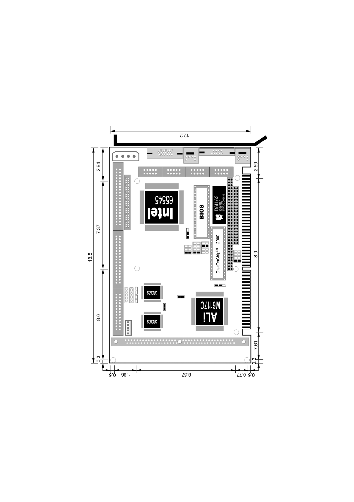
1.3 Board Dimensions
4
Page 11

Chapter 2
Unpacking
This chapter explains unpacking the board, checking the equipment
and documentation and where to go from there.
2.1 Opening the Delivery Package
The HS-3000/4M is packed in an anti-static bag. The board has
components that are easily damaged by static electricity. Do not
remove the anti-static wrapping until proper precautions have been
taken. Safety Instructions in front of this manual describe anti-static
precautions and procedures.
2.2 Inspection
After unpacking the board, place it on a raised surface and carefully
inspect the board for any damage that might have occurred during
shipment. Ground the board and exercise extreme care to prevent
damage to the board from static electricity. Integrated circuits will
sometimes come out of their sockets during shipment. Examine all
integrated circuits, particularly the BIOS, processor, memory modules,
ROM-Disk, and keyboard controller chip to ensure that they are firmly
seated. The HS-3000/4M delivery package contains the following
items:
HS-3000/4M Board x 1
IDE port flat cable x 1
FDD port flat cable x 1
Printer + one COM flat cable with bracket x 1
Two COM flat cable with bracket x 1
Utility CD Disk x 1
User’s Manual x 1
5
Page 12

It is recommended that you keep all the parts of the delivery package
intact and store them in a safe/dry place for any unforeseen event
requiring the return shipment of the product. In case you discover any
missing and/or damaged items from the list of items, please contact
your dealer immediately.
6
Page 13

Chapter 3
Hardware Installation
This chapter provides the information on how to install the hardware
using the HS-3000/4M. This chapter also contains information related
to jumper settings of switch, watchdog timer, and the DiskOnChip
address selection etc.
3.1 Before Installation
After confirming your package contents, you are now ready to install
your hardware. The following are important reminders and steps to take
before you begin with your installation process.
1. Make sure that all jumper settings match their default settings
and CMOS setup correctly. Refer to the sections on this chapter
for the default settings of each jumper.
2. Go through the connections of all external devices and make
sure that they are installed properly and configured correctly
within the CMOS setup. Refer to the sections on this chapter for
the detailed information on the connectors.
3. Keep the manual and diskette in good condition for future
reference and use.
7
Page 14
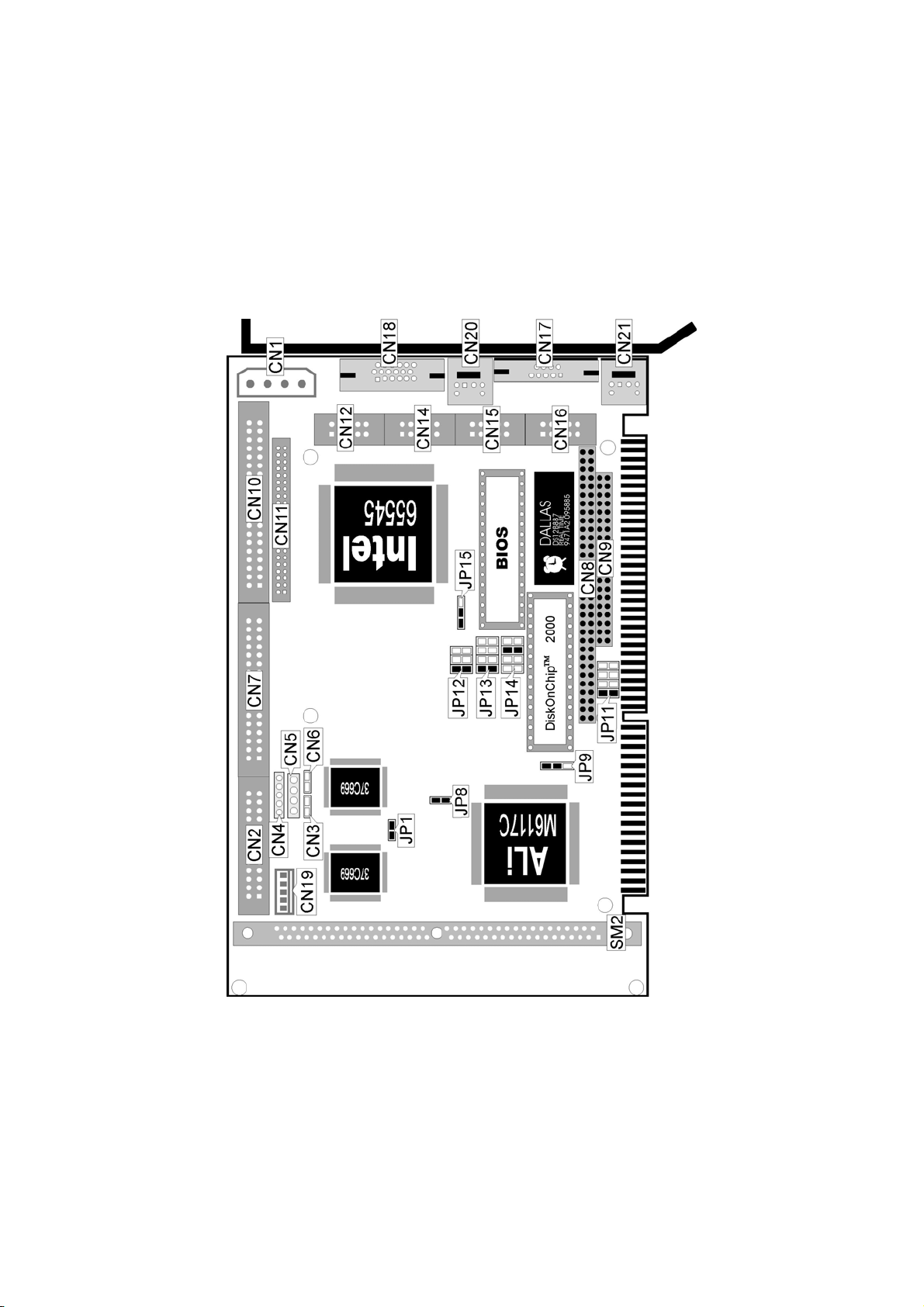
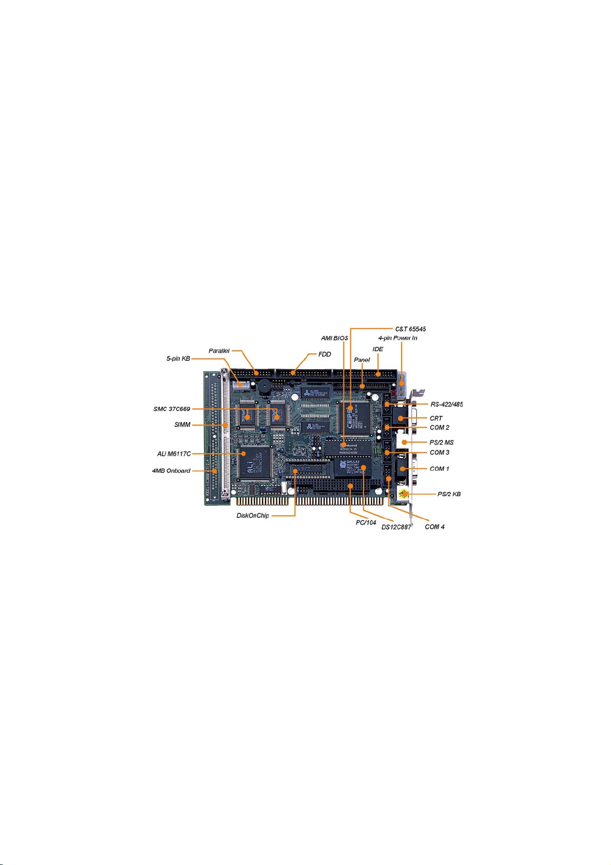
3.2 Board Layout
8
Page 15

3.3 Jumper List
Jumper
JP1
JP8
JP9 WDT Active Type Select: Reset System Short 1-2 10
JP11 DiskOnChipTM Address Select: D000 Short 1-2 10
JP12
JP13
JP14 WDT Out Period Select: 1 sec. Short 5-6 10
JP15 Flash ROM Type Select: 29C010 Short 1-2 23
COM 4 Use RS-232 or RS-422/485 Select:
RS-232
IRQ12 Enabled/Disabled Select: Enabled Short 18
RS-422/485 Receiver Enabled/Disabled Select:
Always Enabled
RS-422/485 Transmitter Enabled/Disabled
Select: Always Enabled
Definition Setting Page
Open 17
Short 1-2 17
Short 1-2 17
3.4 Connector List
Connector
CN1 4-pin Power Connector 21
CN2 Parallel Connector 21
CN3 Reset Button Connector 21
CN4 Keylock Connector 21
CN5 Speaker Connector 19
CN6 IDE LED Connector 21
CN7 Floppy Connector 22
CN8 PC/104 Bus 64-pin Connector 23
CN9
CN10 IDE Connector 20
CN11 Panel Connector 12
CN12 RS-422/485 Connector 17
CN14 COM 2 Connector (5x2 header) 17
CN15 COM 3 Connector (5x2 header) 17
CN16 COM 4 Connector (5x2 header) 17
CN17 COM 1 Connector (DB9) 17
CN18 15-pin CRT Connector 12
CN19 5-pin Keyboard Connector 18
CN20 PS/2 6-pin Mini DIN Mouse Connector 18
CN21
PC/104 Bus 40-pin Connector 23
PS/2 6-pin Mini DIN Keyboard Connector 18
Definition Page
9
Page 16

3.5 DiskOnChip Address Setting
TM
The DiskOnChip
without a FDD or a HDD. DiskOnChip
drive C or A. With DiskOnChip
function allows the system to boot or operate
TM
modules may be formatted as
TM
, user may also execute DOS
commands such as FORMAT, SYS, COPY, XCOPY, DISCOPY and
DISKCOMP etc.
The U9 location onboard the HS-3000/4M is the DiskOnChip module
socket. Jumper JP11 assigns the address setting of the installed
module. Setting the 8 pins of JP11 allows you to select the starting
memory address of the DiskOnChip
TM
(D.O.C.). If you have additional
memory devices in the system, please set both at different memory
address mapping to avoid the mapping area conflicts.
JP11: DiskOnChip Address Select
JP11 Address
Short 1-2 (default) D000
Short 3-4 D800
Short 5-6 E000
Short 7-8 E800
2
1
8
7
3.6 Watchdog Timer
There are three access cycles of watchdog timer as Enable, Refresh and
Disable. The Enable cycle should proceed by READ PORT 443H. The
Disable cycle should proceed by READ PORT 043H. A continue Enable
cycle after a first Enable cycle means Refresh.
Once if the Enable cycle activity, a Refresh cycle is request before the
time-out period for restart counting the WDT Timer’s period. Otherwise, it
will assume that the program operation is abnormal when the time counting
over the period preset of WDT Timer. A System Reset signal to start again
or a NMI cycle to the CPU comes if over.
The JP9 is using for select the active function of watchdog timer in disable
the watchdog timer, or presetting the watchdog timer activity at the reset
trigger, or presetting the watchdog timer activity at the NMI trigger.
10
Page 17

JP9: Watchdog Timer Active Type Select
JP9 Description
Short 1-2 (default) System Reset
Short 2-3
Open Disabled
Active NMI
1
3
JP14: Watchdog Timer Out Period Select
Period PINS 1-2 PINS 3-4 PINS 5-6 PINS 7-8
1 sec
(default)
2 sec Open Open Short Short
10 sec Open Short Open Open
20 sec Open Short Open Short
110 sec Short Open Open Open
220 sec Short Open Open Short
The watchdog timer is disabled after the system power-on. The
watchdog timer can be enabled by a Enable cycle with reading the
control port (443H), a Refresh cycle with reading the control port
(443H) and a Disable cycle by reading the watchdog timer disable
control port (043H). After a Enable cycle of WDT, user must constantly
proceed a Refresh cycle to WDT before its period setting comes ending
of every 1, 2, 10, 20, 110 or 220 seconds (Please reference to the
selection table of JP14 for WDT Time Out period setting). If the Refresh
cycle does not active before WDT period cycle, the onboard WDT
architecture will issue a Reset or NMI cycle to the system. The
watchdog timer controlled by two I/O ports.
Open Open Short Open
2
1
8
7
443H I/O Read Enable/Refresh cycle
043H I/O Read Disable cycle
The following sample program shows how to Enable, Disable and
Refresh the watchdog timer:
WDT_EN_RF EQU 0433H
WDT_DIS EQU 0043H
WT_Enable PUSH AX ; keep AX DX
PUSH DX
MOV DX,WDT_EN_RF ; enable the WDT
IN AL,DX
POP DX ; get back AX, DX
POP AX
RET
11
Page 18

WT_Refresh PUSH AX ; keep AX, DX
PUSH DX
MOV DX,WDT_ET_RF ; refresh the WDT
IN AL,DX
POP DX ; get back AX, DX
POP AX
RET
WT_DISABLE PUSH AX
PUSH DX
MOV DX,WDT_DIS ; disable the WDT
IN AL,DX
POP DX ; get back AX, DX
RET
POP AX
3.7 VGA Controller
The onboard C&T 65545 CRT/Panel display controller provides up to
1024 x 768 at 16 colors resolution. The HS-3000/4M provides two
connection methods of CRT and Panel device. CN18 offers a 15-pin
CRT connector, and CN11 offers a 50-pin Panel connector.
CN18: CRT Connector (8x2 header)
PIN Description PIN Description
1 RED 2 GREEN
3 BLUE 4 N/C
5
GND
6
GND
7 GND 8 GND
9 N/C 10 GND
11 N/C 12 N/C
13 HSYNC 14 VSYNC
15 N/C
5
10
15
1
6
11
The HS-3000/4M provides a 44-pin 2.0mm pitch header connector
(CN11).
CN11: Panel Connector
CN11 Description CN11 Description
1 +12V 2 +12V
3 GND 4 GND
5 PVcc 6 PVcc
7 FPVee 8 GND
9 P0 10 P1
11 P2 12 P3
…More on next page…
12
Page 19

CN11 Description CN11 Description
13 P4 14 P5
P
15
6
16
17 P8 18 P9
19 P10 20 P11
21 P12 22 P13
23 P14 24 P15
P
25
16
26
27 P18 28 P19
29 P20 30 P21
31 P22 32 P23
33 GND 34 GND
35 SHFCLK 36 FLM
37 M 38 LP
39 GND 40 ENABKL
41
GND
42
43 VCC 44 VCC
2
P7
P17
ASHFCLK
44
1
3.7.1 Connectors for Standard LCDs
Sharp LM64183P (640 x 480 DSTN MONO LCD)
Sharp LM64P83(CN1) HS-3000/4M(CN11)
PIN Description PIN Description
1 S 36 FLM
2 CP1 38 LP
3 CP2 35 SHFCLK
4 DISP 5 +5V
5 VDD 6 +5V
6 VSS 3 GND
7 VEE - -17V (external power)
8
DU0
12
9 DU1 11 P2
10 DU2 10 P1
11 DU3 9 P0
12
DL0
16
13 DL1 15 P6
14 DL2 14 P5
15 DL3 13 P4
P3
P7
43
13
Page 20

Sharp LM64C35P (640 x 480 DSTN STN Color)
Sharp LM64C35P(CN1) HS-3000/4M(CN11)
PIN Description PIN Description
1 DL4 16 P7
2 VSS 3 GND
3 DL5 15 P6
4 TD 36 FLM
5 DL6 14 P5
6
7 DL7 13 P4
8 VSS 4 GND
9 VSS 8 GND
10
11 DL0 24 P15
12 VCON - Contrast Adjust
13 DL1 23 P14
14 VDD 5 +5V
15 VSS 33 GND
16 VDD 6 +5V
17 DL2 22 P13
18 DISP 6 +5V
19 DL3 21 P12
20 N/C - 21
22 DU3 17 P8
23 DU4 12 P3
24 DU2 18 P9
25 DU5 11 P2
26 DU1 19 P10
27 VSS 39 GND
28 DU0 20 P11
29 DU6 10 P1
30 VSS 39 GND
31 DU7 9 P0
LP
XCK
VSS
38
35
34
LP
SLFCHK
GND
14
Page 21

Sharp LM64C142(640 x 480 DSTN STN Color)
Sharp LM64C142(CN1) HS-3000/4M(CN11)
PIN Description PIN Description
1 YD 36 FLM
2 LP 38 LP
3 XCX 35 SHFCLK
4 DISP 5 +5V
5 PVDD 6 +5V
6
7 PVEE - +27V (external power)
8 DU0 20 P11
9 DU1 19 P10
10
11 DU3 17 P8
12 DU4 12 P3
13 DU5 11 P2
14 DU6 10 P1
15 DU7 9 P0
PVSS
DU2
3
18
Sharp LM64C142 (CN2) HS-3000/4M(CN11)
PIN Description PIN Description
1 VSS 4 GND
2
3 DL1 23 P14
4 DL2 22 P13
5 DL3 21 P12
6 DL4 16 P7
7 DL5 15 P6
8 DL6 14 P5
9 DL7 13 P4
10 VSS 8 GND
DL0
24
GND
P9
P15
NEC NL8060AC26 (800 x 600 TFT Color)
NEC NL8060AC26(CN1) HS-3000/4M(CN11)
PIN Description PIN Description
1 GND 3 GND
2 Dot Clock 35 SHFCLK
3 GND 4 GND
4 HSYNC 38 LP
5 HSYNC 38 FLM
6 GND 8 GND
7 GND 8 GND
…More on next page…
15
Page 22

NEC NL8060AC26(CN1) HS-3000/4M(CN11)
PIN Description PIN Description
8 GND 8 GND
9 R0 27 P18
10 R1 28 P19
11 R2 29 P20
12 GND 8 GND
13 R3 30 P21
14
15 R5 32 P23
16 GND 39 GND
17 GND 39 GND
18
19 G0 19 P10
20 G1 20 P11
21 G2 21 P12
22 GND 39 GND
23 G3 22 P13
24 G4 23 P14
25
26 GND 41 GND
27 GND 41 GND
28 GND 41 GND
29
30 B1 12 P3
31 B2 13 P4
32 GND 41 GND
33 B3 14 P5
34 B4 15 P6
35 B5 16 P7
36 GND 41 GND
37 DE 37 M
38 PVCC 43 PVCC
39 PVCC 44 PVCC
40
41 MODE - ----
R4
GND
G5
B0
PVCC
31
39
24
11
5
P22
GND
P15
P2
PVCC
16
Page 23

3.8 Serial Port Connectors
The HS-3000/4M’s CN17, 14, 15 and 16 provide four high speeds
NS16C550 compatible USRT with Read/Receive 16 byte FIFO serial
ports.
CN14, 15, 16: COM 2~COM 4 Connector (5x2 header)
PIN Description PIN Description
2
1 2
1
3
5
7
9
9
5
16
4
6
8
10
1 DCD 2 DSR
3 RXD 4 RTX
5
TXD
6
CTX
7 DTR 8 RI
9 GND 10 N/C
CN17: COM 1 Connector (DB9)
PIN Description PIN Description
1 DCD 6 DSR
2 RXD 7 RTS
3 TXD 8 CTS
4
DTR
9
5 GND
RI
JP1: COM 4 Use RS-232 or RS-422/485 Select
JP1 Description
Short RS-232
Open (default) RS-422/485
CN12: RS-422/485 Connector (5x2 header)
PIN Description PIN Description
1 TX- 2 TX+
3 RX+ 4 RX-
5 GND 6 RTS-
7 RTS+ 8 CTS+
9 CTS- 10 N/C
2
1
4
3
6
5
8
7
10
9
17
Page 24

JP12: RS-422/485 Receiver Enabled/Disabled Select
JP12 Description
Short 1-2(default) Always Enable
Short 3-4 Enable by writing the REG.2EFh BIT1=1
All Open Always Disable
2
1
JP13: RS-422/485 Transceiver Enabled/Disabled Select
JP13 Description
Short 1-2 (default) Always Enable
Short 3-4 Enable by ”-RTS” signal
Short 5-6 Enable by writing the REG.2EFh BIT0=1
Short 7-8 Always Disable
2
1
8
7
3.9 Keyboard & Mouse Connector
The HS-3000/4M offers two connection methods for keyboard
connector, at location CN19 is 5-pin connector, location CN21 is PS/2
6-pin Mini DIN connector.
CN19: 5-pin Keyboard Connector
PIN Description
Keyboard Clock
1
2 Keyboard Data
3 N/C
4 GND
5 +5V
12 34 5
N/C
Keyboard
Data
Clock
Keyboard
GND
+5V
6
5
CN21: PS/2 6-pin Mini DIN Keyboard Connector
PIN Description
1 Keyboard Data
2
N/C
3 GND
4 +5V
5 Keyboard Clock
6 N/C
Keyboard
Clock
N/C
5
6
18
GND
3
Keyboard
1
Data
2
N/C
+5V
4
Page 25

The HS-3000/4M has a PS/2 mouse connector onboard uses IRQ12. If
you do not use the PS/2 mouse and wish to assign IRQ12 for other
purposes, you may change JP8 do disconnect PS/2 interrupt from
IRQ12.
JP8: IRQ12 Enabled/Disabled Select
JP8 Description
Open Disabled
Short (default) Enabled
NOTE: If you want to use PS/2 mouse, please make sure JP8 is Short.
1 2
CN20: PS/2 6-pin Mini DIN Mouse Connector
PIN Description
1 Mouse Data
2 N/C
3
GND
4 +5V
5 Mouse Clock
6 N/C
Mouse
Clock
N/C
5
6
1
2
4
Mouse
Data
N/C
+5V
GND
3
3.10 Speaker Connector
The HS-3000/4M has its own buzzer, and CN5 allows user to connect
to the external speaker.
CN5: Speaker Connector
PIN Description
1 Speaker
2 N/C
3 GND
4 +5V
1234
19
Page 26

3.11 PCI E-IDE Drive Connector
One standard 40-pin header daisy-chain driver connector provides as
CN10 with following pin assignment. Total two IDE (Integrated Device
Electronics) drivers may connect.
CN10: IDE Connector
PIN Description PIN Description
1 Reset 2 GND
3 DATA 7 4 DATA 8
5 DATA 6 6 DATA 9
7 DATA 5 8 DATA 10
9
11 DATA 3 12 DATA 12
13 DATA 2 14 DATA 13
15 DATA 1 16 DATA 14
17 DATA 0 18 DATA 15
19 GND 20 N/C
21 N/C 22 GND
23 IOW# 24 GND
25
27 N/C 28 Bale – Default
29 N/C 30 GND - Default
31 Interrupt 32 IOCS16# - Default
33 SA1 34 N/C
35
37 HDC CS0 38 HDC CS1#
39 HDD Active 40 GND
DATA 4
IOR#
SA0
10
26
36
DATA 11
GND
SA2
20
2
1
40
39
Page 27

3.12 Parallel Connector
A standard 26-pin flat cable driver connector provides as CN2 with
following pin assignment for connection to parallel printer.
CN2: Parallel Connector
PIN Description PIN Description
1 STROBE 14 Auto Form Feed
2 DATA 0 15 ERROR#
3 DATA 1 16 Initialize
4 DATA 2 17 Printer Select LN#
5 DATA 3 18 GND
6 DATA 4 19 GND
7 DATA 5 20 GND
8 DATA 6 21 GND
14
DATA 7
22
9
10 Acknowledge 23 GND
11 Busy 24 GND
12 Paper Empty 25 GND
13 Printer Select 26 GND
GND
26
1
13
3.13 Power and LED Connectors
The following provides the pin information for CN1 4-pin power
connector, CN3 reset button connector, CN4 power LED and keylock
connector, and CN6 is IDE LED.
CN1: 4-pin Power Connector
PIN Description
1 VCC
2 GND
3 GND
4
CN3: Reset Button Connector
PIN Description
1 Reset Signal
2 GND
+12V
1 2
21
Page 28

CN4: Keylock and Power LED Connector
PIN Description
1
2 N/C
3 GND
4 Keylock
5 GND
CN6: IDE LED Connector
Power LED
PIN Description
1 VCC
2
HDD Active
1234 5
Power LED
1 2
Keylock
3.14 Floppy Disk Drive Connector
The HS-3000/4M uses a standard 34-pin header connector, CN7, for
floppy disk drive connection. A total of two FDD drives may be
connected at any given time.
CN7: Floppy Connector
PIN Description PIN Description
1 GND 2 Reduce Write
3 GND 4 N/C
5 GND 6 N/C
7 GND 8 Index#
9 GND 10 MTR0#
11 GND 12 DS1#
13 GND 14 DS0#
15 GND 16 MTR1#
17 GND 18 Direction#
19 GND 20 Step#
21 GND 22 Write Data#
23
25 GND 26 Track 0#
27 GND 28 Write Protect#
29 N/C 30 Read Data#
31 GND 32 HDSEL#
33 N/C 34 Disk Change#
GND
24
Write Gate#
22
2
1
34
33
Page 29

3.15 Flash ROM Type
The JP15 provides in selection the type of Flash ROM type. If VPP is
+5V please set 29C010, VPP is +12V please set 28F010.
JP15: Flash ROM Type Select
Options Setting
29C010 (default) Short 1-2
28F010 Short 2-3
13
3.16 System Memory
The HS-3000/4M has one SIMM socket, provides 72-pin SIMM
module. The memory access time should be 70ns or less. The
HS-3000/4M has one SIM socket and 4MB RAM onboard.
Memory Type Configuration
SM1
4MB RAM Onboard
BANK0 BANK1 Total
256K x 2 256K x 2 1M
512K x 2 ---- 1M
512K x 2 512K x 2 2M
512K x 2 1M x 2 3M
512K x 2 4M x 2 9M
1M x 2 ---- 2M
1M x 2 1M x 2 4M
1M x 2 4M x 2 10M
2M x 2 ---- 4M
2M x 2 2M x 2 8M
2M x 2 4M x 2 12M
4M x 2 ---- 8M
4M x 2 4M x 2 16M
SM2
3.17 PC/104 Bus Connection
The PC/104 expansion bus offers provisions to connect all types of
PC/104 modules. With the PC/104 bus being known as the new
generation of industrial embedded 16-bit PC standard bus, thousands
of PC/104 modules from multiple venders can be easily installed
onboard. The detailed pin assignment of the PC/104 expansion bus
connectors CN8 and CN9 are listed on the following tables.
23
Page 30

NOTE: The PC/104 connector allows direct plugging or stack-through
piling of PC/104 modules without requiring the PC/104 mounting
kit.
CN8: PC/104 64-pin Connector
PIN Description PIN Description
1 IOCHECK* 33 GND
2 SD7 34 RESETDRV
3 SD6 35 +5V
4
SD5
36
5 SD4 37 -5V
6 SD3 38 DRQ2
7 SD2 39 -12V
8 SD1 40 NOW*
9 SD0 41 +12V
10 IOCHRDY 42 GND
11 AEN 43 SMEMW*
12 SA19 44 SMEMR*
13 SA18 45 IOW*
14 SA17 46 IOR*
15
SA16
47
16 SA15 48 DRQ3
17 SA14 49 DACK1*
18 SA13 50 DRQ1
19 SA12 51 REFRESH*
20 SA11 52 SYSCLK
21 SA10 53 IRQ7
22 SA9 54 IRQ6
23 SA8 55 IRQ5
24 SA7 56 IRQ4
25 SA6 57 IRQ3
26
SA5
58
27 SA4 59 TC
28 SA3 60 BALE
29 SA2 61 +5V
30
SA1
62
31 SA0 63 GND
32 GND 64 GND
2
IRQ9
DACK3*
DACK2*
OSC
64
24
1
63
Page 31

CN9: PC/104 40-pin Connector
PIN Description PIN Description
1 GND 21 GND
2 MEMCS16* 22 SBHE*
3 IOSC16* 23 LA23
4 IRQ10 24 LA22
5
6 MSDATA 26 LA20
7 IRQ15 27 LA19
8 IRQ14 28 LA18
9 DACK0* 29 LA17
10 DRQ0 30 MEMR*
11 DACK5* 31 MEMW*
12 DRQ5 32 SD8
13 DACK6* 33 SD9
14 DRQ6 34 SD10
15 DACK7* 35 SD11
16
17 +5V 37 SD13
18 MASTER* 38 SD14
19 GND 39 SD15
20
IRQ11
DRQ7
GND
25
36
LA21
SD12
40 N/C
2
1
40
39
25
Page 32

This page is intentionally left blank.
26
Page 33

Chapter 4
AMI BIOS Setup
The HS-3200/4M uses Award ISA BIOS for the system configuration.
The AMI BIOS setup program is designed to provide the maximum
flexibility in configuring the system by offering various options that
could be selected for end-user requirements. This chapter is written to
assist you in the proper usage of these features.
4.1 Starting Setup
The Award BIOS is immediately activated when you first power on the
computer. The BIOS reads the system information contained in the
CMOS and begins the process of checking out the system and
configuring it. When it finishes, the BIOS will seek an operating system
on one of the disks and then launch and turn control over to the
operating system.
While the BIOS is in control, the Setup program can be activated in one
of two ways:
1. By pressing <Del> immediately after switching the system on,
or
2. By pressing the <Del> key when the following message
appears briefly at the bottom of the screen during the POST
(Power On Self Test).
Press DEL to enter SETUP.
If the message disappears before you respond and you still wish to
enter Setup, restart the system to try again by turning it OFF then ON or
pressing the "RESET" button on the system case. You may also restart
by simultaneously pressing <Ctrl>, <Alt>, and <Delete> keys. If you do
not press the keys at the correct time and the system does not boot, an
error message will be displayed and you will again be asked to...
PRESS F1 TO CONTINUE, DEL TO ENTER SETUP
27
Page 34

4.2 Using Setup
In general, you use the arrow keys to highlight items, press <Enter> to
select, use the <PageUp> and <PageDown> keys to change entries,
press <F1> for help and press <Esc> to quit. The following table
provides more detail about how to navigate in the Setup program using
the keyboard.
Up arrow Move to previous item
Down arrow Move to next item
Left arrow Move to the item in the left hand
Right arrow
Esc key Main Menu -- Quit and not save changes into CMOS
PgUp key Increase the numeric value or make changes
PgDn key Decrease the numeric value or make changes
+ key Increase the numeric value or make changes
- key
F1 key General help, only for Status Page Setup Menu and Option
(Shift)F2 key Change color from total 16 colors. F2 to select color
F3 key Calendar, only for Status Page Setup Menu
F4 key Reserved
F5 key
F6 key Load the default CMOS value from BIOS default table, only
F7 key Load the default
F8 key Reserved
F9 key Reserved
F10 key
Move to the item in the right hand
Status Page Setup Menu and Option Page Setup Menu -Exit current page and return to Main Menu
Decrease the numeric value or make changes
Page Setup Menu
forward, (Shift) F2 to select color backward
Restore the previous CMOS value from CMOS, only for
Option Page Setup Menu
for Option Page Setup Menu
Save all the CMOS changes, only for Main Menu
4.2.1 Getting Help
Press F1 to pop up a small help window that describes the appropriate
keys to use and the possible selections for the highlighted item. To exit
the Help Window press <Esc> or the F1 key again.
28
Page 35

4.3 Main Menu
Once you enter the Award BIOS CMOS Setup Utility, the Main Menu
will appear on the screen. The Main Menu allows you to select from
several setup functions and two exit choices. Use the arrow keys to
select among the items and press <Enter> to enter the sub-menu.
AMI BIOS Setup Utility – Version 1.23
© 1999 American Megatrends, Inc. All Rights Reserved
STANDARD CMOS SETUP
Advanced CMOS Setup
Advanced Chipset Setup
PCI / Plug and Play Setup
Auto-Detect Hard Disks
Change User Password
Change Language Setting
Auto Configuration with Optional Settings
Auto Configuration with Fail Safe Settings
Save Settings and Exit
Load configuration settings giving highest performance
Esc: Exit : Sel F2/F3: Color F10: Save & Exit
Peripheral Setup
Exit Without Saving
29
Page 36

4.4 Standard CMOS Setup
The Standard Setup is used for the basic hardware system
configuration. The main function is for Data/Time and Floppy/Hard Disk
Drive settings. Please refer to the following screen for the setup. When
the IDE hard disk drive you are using is larger than 528MB, please set
the HDD mode to LBA mode. Please use the IDE Setup Utility in BIOS
SETUP to install the HDD correctly.
AMI BIOS Setup – Standard CMOS Setup
© 1999 American Megatrends, Inc. All Rights Reserved
Data (mm:dd:yy):Fri, Dec 20 2002 Base Memory: 640 KB
Time (hh:mm:ss):14:50:1 Ext Memory: 3 MB
Type CYLS HEAD PRECOMP LANDZ SECTOR MODE
Pri Master : Auto Off
Pri Slave : Auto Off
Floppy Drive A : 1.44 MB 3.5
Floppy Drive B : Not Installed
Boot Sector Virus Protection: Disabled
Month:
Day:
Yea r:
Jan – Dec
01 – 31
1901 – 2099
ESC: Quit : Sel
PgUp/PgDn: Modify
F1: Help F2/F3: Color
30
Page 37

4.5 Advanced CMOS Setup
This section allows you to configure your system for the basic
operation. You have the opportunity to select the system’s default
speed, boot-up sequence, keyboard operation, shadowing and
security.
AMIBIOS SETUP – ADVANCED CMOS SETUP
(C)2001 American Megatrends, Inc. All Rights Reserved
Quick Boot Disabled Available Options:
1st Boot Device IDE-0 ` Disabled
2nd Boot Device Floppy Enabled
3rd Boot Device Disabled
Try Other Boot Devices Yes
BootUp Num-Lock On
Floppy Drive Swap Disabled
Floppy Drive Seek Disabled
PS/2 Mouse Support Enabled
System Keyboard Present
Primary Display VGA/EGA
Password Check Setup
Wait For ‘F1’ If Error Enabled
C000, 32k Shadow Disabled
C800, 32k Shadow Disabled
D000, 32k Shadow Disabled
D800, 32k Shadow Disabled ESC:Exit :Sel
PgUp/PgDn: Modify
F1:Help F2/F3:Color
31
Page 38

4.6 Advanced Chipset Setup
This section allows you to configure the system based on the specific
features of the installed chipset. This chipset manages bus speeds and
the access to the system memory resources, such as DRAM and the
external cache. It also coordinates the communications between the
conventional ISA and PCI buses. It must be stated that these items
should never be altered. The default settings have been chosen
because they provide the best operating conditions for your system.
You might consider and make any changes only if you discover that the
data has been lost while using your system.
AMIBIOS SETUP – ADVANCED CHIPSET SETUP
(C)1999 American Megatrends, Inc. All Rights Reserved
Available Options:
AT Bus Clock 14.318/2 ` Disabled
Slow Refresh (us) 120 Enabled
Memory Hole At 15-16M Disabled
RAS Precharge time 3.5T
RAS Active Time Insert Wait Enabled
CAS Precharge Time Insert Wait Enabled
Memory Write Insert Wait Enabled
Memory Miss Read Insert Wait Enabled
ISA Write cycle end Insert Wait Enabled
I/O Recovery Enabled
I/O Recovery Period 0.75 us
On-Chip I/O Recovery Disabled
16Bit ISA Insert Wait Enabled
ESC:Exit :Sel
PgUp/PgDn: Modify
F1:Help F2/F3:Color
32
Page 39

4.7 PCI / Plug And Play Setup
This section describes configuring the PCI bus system. PCI, or
ersonal Computer Interconnect, is a system that allows I/O devices to
P
operate at speeds nearing the speed the CPU itself uses when
communicating with its own special components. This section covers
some very technical items and it is strongly recommended that only
experienced users should make any changes to the default settings.
AMIBIOS SETUP – PCI / PLUG AND PLAY SETUP
(C)1999 American Megatrends, Inc. All Rights Reserved
Plug and Play Aware O/S No Available Options:
DMA Channel 0 PnP ` No
DMA Channel 1 PnP Yes
DMA Channel 3 PnP
DMA Channel 5 PnP
DMA Channel 6 PnP
DMA Channel 7 PnP
IRQ3 PnP
IRQ4 PnP
IRQ7 PnP
IRQ9 PnP
IRQ10 PnP
IRQ11 PnP ESC:Exit
IRQ14 PnP PgUp/PgDn: Modify
IRQ15 PnP F1:Help F2/F3:Color
:Sel
33
Page 40

4.8 Peripheral Setup
The IDE hard drive controllers can support up to two separate hard
drives. These drives have a master/slave relationship that is
determined by the cabling configuration used to attach them to the
controller. Your system supports two IDE controllers--a primary and a
secondary--so you can install up to four separate hard disks.
PIO means Programmed Input/Output. Rather than having the BIOS
issue a series of commands to affect the transfer to or from the disk
drive, PIO allows the BIOS to tell the controller what it wants and then
let the controller and the CPU perform the complete task by them. This
is much simpler and more efficient (also faster).
AMIBIOS SETUP – PERIPHERAL SETUP
(C)1999 American Megatrends, Inc. All Rights Reserved
OnBoard IDE Primary Available Options:
OnBoard FDC Auto ` Disabled
OnBoard Serial Port 1 Auto Primary
OnBoard Serial Port 2 Auto Secondary
Serial Port2 Mode Normal Both
Receiver Polarity Non-Inverted
Transmitter Polarity Non-Inverted
OnBoard Serial Port3 Audo
Serial Port3 IRQ Auto
OnBoard Serial Port4 Auto
Serial Port4 Mode Normal
Serial Port4 IRQ Auto
Receiver Polarity Non-Inverted
Transmitter Polarity Non-Inverted
OnBoard Prarllel Port Auto
Parallel Port Mode ECP
EPP Version N/A
Parallel Port IRQ Auto
Parallel Port DMA Channel Auto ESC:Exit
PgUp/PgDn: Modify
F1:Help F2/F3:Color
:Sel
34
Page 41

4.9 Auto-Detect Hard Disks
This option detects the parameters of an IDE hard disk drive, and
automatically enters them into the Standard CMOS Setup screen.
Up to four IDE drives can be detected, with parameters for each
appearing in sequence inside a box. To accept the displayed entries,
press the “Y” key; to skip to the next drive, press the “N” key. If you
accept the values, the parameters will appear listed beside the drive
letter on the screen.
AMIBIOS SETUP – PERIPHERAL SETUP
(C)1999 American Megatrends, Inc. All Rights Reserved
Standard CMOS Setup
Advanced CMOS Setup
Advanced Chipset Setup
Power Management Setup
PCI / Plug and Play Setup
Peripheral Setup
Hardware Monitor Setup
Auto-Detect Hard Disks
Change User Password
Change Supervisor Password
Auto Configuration with Optimal Settings
Auto Configuration with Fail Safe Settings
Save Settings and Exit
Exit Without Saving
Standard CMOS setup for changing time, date, hard disk type, etc.
ESC:Exit :Sel F2/F3: Color F10: Save & Exit
35
Page 42

4.10 Change Supervisor/User Password
AMIBIOS SETUP – PERIPHERAL SETUP
(C)1999 American Megatrends, Inc. All Rights Reserved
Standard CMOS Setup
Advanced CMOS Setup
Advanced Chipset Setup
Power Management Setup
Enter new supervisor password: _
Change Supervisor Password
Auto Configuration with Optimal Settings
Auto Configuration with Fail Safe Settings
Save Settings and Exit
Exit Without Saving
Standard CMOS setup for changing time, date, hard disk type, etc.
ESC:Exit :Sel F2/F3: Color F10: Save & Exit
You can set either supervisor or user password, or both of then. The
differences between are:
supervisor password: can enter and change the options of the setup
menus.
user password: just can only enter but do not have the right to change the
options of the setup menus.
When you select this function, the following message will appear at the
center of the screen to assist you in creating a password.
ENTER PASSWORD:
Type the password, up to eight characters in length, and press
<Enter>. The password typed now will clear any previously entered
password from CMOS memory. You will be asked to confirm the
password. Type the password again and press <Enter>. You may also
press <Esc> to abort the selection and not enter a password.
To disable a password, just press <Enter> when you are prompted to
enter the password. A message will confirm the password will be
disabled. Once the password is disabled, the system will boot and you
can enter Setup freely.
PASSWORD DISABLED.
When a password has been enabled, you will be prompted to enter it
every time you try to enter Setup. This prevents an unauthorized
36
Page 43

person from changing any part of your system configuration.
Additionally, when a password is enabled, you can also require the
BIOS to request a password every time your system is rebooted. This
would prevent unauthorized use of your computer.
You determine when the password is required within the BIOS
Features Setup Menu and its Security option (see Section 3). If the
Security option is set to “System”, the password will be required both at
boot and at entry to Setup. If set to “Setup”, prompting only occurs
when trying to enter Setup.
4.11 Auto Configuration with Optimal
Settings
When you press <Enter> on this item you will get a confirmation dialog
box with a message shown below. This option allows you to
load/restore the BIOS default values permanently stored in the BIOS
ROM. Pressing ‘Y’ loads the BIOS default values for the most stable,
minimal-performance system operations.
AMIBIOS SETUP – PERIPHERAL SETUP
(C)1999 American Megatrends, Inc. All Rights Reserved
Standard CMOS Setup
Advanced CMOS Setup
Advanced Chipset Setup
Power Management Setup
Load high performance settings (Y/N) ? N
Change Supervisor Password
Auto Configuration with Optimal Settings
Auto Configuration with Fail Safe Settings
Save Settings and Exit
Exit Without Saving
Standard CMOS setup for changing time, date, hard disk type, etc.
ESC:Exit :Sel F2/F3: Color F10: Save & Exit
37
Page 44

4.12 Auto Configuration with Fail Safe
Settings
When you press <Enter> on this item you get a confirmation dialog box
with a message similar to the figure below. This option allows you to
load/restore the default values to your system configuration, optimizing
and enabling all high performance features. Pressing ‘Y’ loads the
default values that are factory settings for optimal performance system
operations.
AMIBIOS SETUP – PERIPHERAL SETUP
(C)1999 American Megatrends, Inc. All Rights Reserved
Standard CMOS Setup
Advanced CMOS Setup
Advanced Chipset Setup
Power Management Setup
Load failsafe settings (Y/N) ? N
Change Supervisor Password
Auto Configuration with Optimal Settings
Auto Configuration with Fail Safe Settings
Save Settings and Exit
Exit Without Saving
Standard CMOS setup for changing time, date, hard disk type, etc.
ESC:Exit :Sel F2/F3: Color F10: Save & Exit
38
Page 45

4.13 Save Settings and Exit
Pressing <Enter> on this item asks for confirmation:
AMIBIOS SETUP – PERIPHERAL SETUP
(C)1999 American Megatrends, Inc. All Rights Reserved
Standard CMOS Setup
Advanced CMOS Setup
Advanced Chipset Setup
Power Management Setup
Save current settings and exit (Y/N) ? Y
Change Supervisor Password
Auto Configuration with Optimal Settings
Auto Configuration with Fail Safe Settings
Save Settings and Exit
Exit Without Saving
Standard CMOS setup for changing time, date, hard disk type, etc.
ESC:Exit :Sel F2/F3: Color F10: Save & Exit
Pressing “Y” stores the selections made in the menus in CMOS – a
special section of memory that stays on after you turn your system off.
The next time you boot your computer, the BIOS configures your
system according to the Setup selections stored in CMOS. After saving
the values the system is restarted again.
39
Page 46

4.14 Exit Without Saving
Pressing <Enter> on this item asks for confirmation:
Quit without saving (Y/N)? Y
This allows you to exit Setup without storing in CMOS any change. The
previous selections remain in effect. This exits the Setup utility and
restarts your computer.
AMIBIOS SETUP – PERIPHERAL SETUP
(C)1999 American Megatrends, Inc. All Rights Reserved
Standard CMOS Setup
Advanced CMOS Setup
Advanced Chipset Setup
Power Management Setup
Quit without saving (Y/N) ? N
Change Supervisor Password
Auto Configuration with Optimal Settings
Auto Configuration with Fail Safe Settings
Save Settings and Exit
Exit Without Saving
Standard CMOS setup for changing time, date, hard disk type, etc.
ESC:Exit :Sel F2/F3: Color F10: Save & Exit
40
Abandon all Data & Exit Setup
 Loading...