

Page 1
SERVICE MANUAL
& PARTS LIST
REF. NO. S/M-883
MAR. 2005
MODULE NO.
QW-2914
GW-002J
Ver.1 : Apr. 2007
R
(WITHOUT PRICE)
Page 2

CONTENTS
Page
1. SPECIFICATIONS: MODULE QW-2914 .................................................... 1
2. OPERATION CHART: MODULE QW-2914 ............................................... 2
3. DRAWINGS: MODULE QW-2914
3-1. LCD DIAGRAM ............................................................................................ 10
3-2. CIRCUIT DIAGRAM .....................................................................................11
3-3. CHECKING TERMINALS AND COMPONENTS ......................................... 12
4. EXPLODED VIEW: MODULE QW-2914 ................................................... 14
5. PARTS LIST: MODULE QW-2914 ............................................................ 15
6. PRECAUTIONS FOR REPAIR: MODULE QW-2914
6-1. AC (ALL CLEAR) AND REMOVING OF MODULE .....................................16
6-2. ACCURACY CHECKING .............................................................................16
6-3. SOLAR CELL-PCB ASS'Y CONTACT CHECKING....................................17
6-4. HOW TO CHECK TILT SENSOR................................................................. 17
7. TROUBLESHOOTING FOR TIME RECEPTION: MODULE QW-2914 .... 18
8. CHANGES TO THE PCB ASS'Y ...............................................................19
Page 3
1. SPECIFICATIONS: MODULE QW-2914
Item Detail
Battery CTL1616 (Storage battery)
Note: Use CTL1616 only. Other storage battery or CR1616 can cause
damage to the watch.
Battery life Approx. 8.5 months (from full charged condition)
Current consumption 1.161 µA maximum
Alarm system Piezo plate on Cover/Back
Accuracy ±15 sec./month
Accuracy setting system Trimmer capacitor
Accuracy checking See page 16
Functions • Electro-luminescent backlight
Full auto EL light
• Solar powered
• Battery power indicator
• Power Saving (Turns off the display when the watch is left in the dark)
• Time calibration signal reception
Auto receive (Three times a day at 1:00AM, 2:00AM and 3:00AM)
Manual receive
Last date/time received display
• ReceivableTime Calibration Signals
Fort Collins, Colorado (Call sign: WWVB, Frequency: 60KHz)
Fukushima, Japan (Call sign: JJY, Frequency: 40KHz)
Fukuoka/Saga, Japan (Call sign: JJY, Frequency: 60KHz)
• World Time
29 time zones (30 cities), daylight saving time on/off
• 1/100-sec.stopwatch
Measuring capacity: 23:59'59.99"
Measuring modes: Elapsed time, split time, 1st-2nd place times
• Daily alarms
5 independent daily alarms(4 one-time alarms and 1 snooze alarm)
• Hourly alarms
• Auto-calendar (to year 2039)
• 12/24-hr format
• Regular timekeeping:
hr, min, sec, pm, month, date, day
• Countdown timer
Measuring unit: 1/10 second
Countdown range: 60 minutes
Countdown start time setting range: 1 to 60 minutes (1-minutes increments)
— 1 —
Page 4

2. OPERATION CHART: MODULE QW-2914
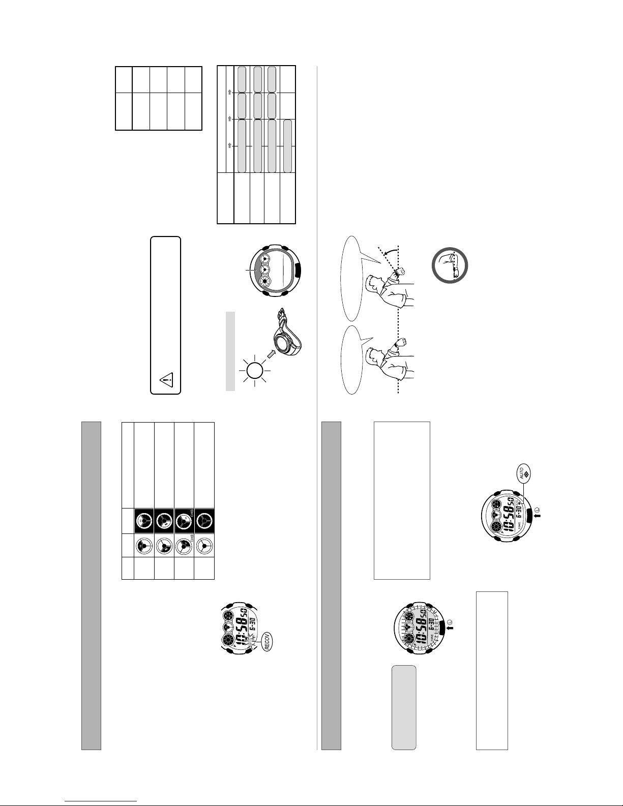
White indicates “ON”.
Black-On-White White-On-Black
Black indicates “ON”.
This watch is available with either of two different LCD types: light
background with dark figures (black-on-white) or dark background
with light figures (white-on-black).
Note that all of the samples in this manual show the black-on-
white type LCD.
Alarm Time
World Time Mode Alarm Mode
Current Time in Selected City
Alarm Number
City Code
Mode Indicator
Timer Time
Elapsed Time
Stopwatch Mode Timer Mode
Mode Indicator
■ To recover from the sleep state
Power Saving LCD Types
Power Saving causes the watch to enter a sleep state automatically and save power whenever the watch is left in the dark. The Power
Saving feature of the watch is turned on at the factory.
• Note that the watch may also enter the sleep state if the watch is blocked from light by your sleeve.
■ How the sleep state works
Display sleep state
after you place the watch in a well-lit area.
Move the watch to a brightly lit location or press any button. The
watch will also recover from the sleep state if you angle it towards
your eyes for reading (see “To illuminate the display with the auto
• It can take up to two seconds before display figures re-appear
■ To turn Power Saving on and off
light switch”).
The display sleep state is triggered whenever the watch is left in
the dark for about one hour between the hours of 10:00 p.m. and
6:00 a.m.
• The display sleep state causes the display to go blank, except for
Use the procedure under “Configuring Home Time Settings” to turn
Power Saving on or off.
a flashing Power Saving indicator. The alarm and the hourly time
signal continue to operate normally while the watch is in the
display sleep state.
the Stopwatch Mode.
• The watch will not enter the sleep state if it is in the Timer Mode or
Leaving the watch in a drawer or anywhere else it is dark can
cause Power Saving to trigger in order to conserve battery
power.
CC
CC
C button sounds a confirmation tone and cycles through available modes in the sequence shown below.
Power Saving
Indicator
is in the function sleep state, and time calibration signal auto
Function sleep state
The function sleep state is triggered whenever the watch is left in
receive is not performed.
the dark for six or seven days. The power saving indicator stops
flashing and remains on the display to indicate the function sleep
state.
• The alarm and the hourly time signal are disabled while the watch
• Digital timekeeping functions continue to operate normally in the
Modes and Display Screens
function sleep state.
Each press of the
— 2 —
Timekeeping Mode
Graphic Dial
Button
(Screen Switching)
Receive Indicator
Battery Indicator
Button
operation for about two or three minutes.
PM Indicator
(Appears with times
• The display will revert to the Timekeeping Mode automatically if you leave the Alarm Mode screen displayed without performing any
between noon and
midnight.)
Hour, minute,
Button
Button
(Mode switching)
second
Month/Day Day of the Week
Button
(Display Illumination)
A segment appears with the passage of each second of the current minute.
“Receive Indicator”.
Days of the Week
SUN: Sunday MON: Monday TUE: Tuesday WED: Wednesday THU: Thursday FRI: Friday SAT: Saturday
For details about the battery level indicator, see “Battery Level Indicator”. For details about the receive indicator, see
•
•
Changing Display Screen Contents
Each press of the button toggles the lower display contents between the date (month/day) and the day of the week.
Page 5
Time
Exposure
5 minutes
Approximate
24 minutes
48 minutes
8 hours
6 hours22 hours
30 hours109 hours
61 hours222 hours
The following is the daily
Required Daily Charging Time
•
■ Charging Guide
Starting from a full charge, the watch
should be able to continue operating
for about eight months without
■ Charging Precautions
Avoid charging the watch in the following locations, and anywhere
else where the watch may become very hot.
• On the dashboard of an automobile parked in the sun
Outdoor Sunlight
Exposure Level
further charging under the conditions
described below.
Daily Use (All time values are
approximate.)
heat
• Very close to an incandescent light source or other sources of
• In a location exposed to direct sunlight for long periods
Note that the display panel may become black under very high
temperatures. This is temporary, and the display will appear
(Brightness)
amount of charging required
each day to support the
operations under “Daily Use”.
Daylight Through a
Window on an Overcast
Sunlight Through
• Display Illumination: 1.5 seconds
• Alarm: 10 seconds
• Signal reception: 16 minutes
• Display On: 18 hours
Depending on the light source you are using, the
case of the watch may become quite hot during
normal again at lower temperatures.
Lighting (500 lux)
Making sure the watch is regularly
exposed to light ensures stable
operation.
• Charge Times Required to Advance to a Higher Level
charging. Take care to guard against burn injury after
charging.
charging efficiency.
■ To charge the battery
Point the solar panel (display) of the watch at a light source.
• Remember that even a partial blockage of the solar cell reduces
Indoor
a Window
Day (5,000 lux)
Fluorescent
(10,000 lux)
(50,000 lux)
Approximate Exposure Time
2 hours
5 hours
9 hours
Level 4 Level 3 Level 2 Level 1
(50,000 lux)
(Brightness)
Exposure Level
Outdoor Sunlight
Solar Cell
Example: Positioning the watch
an Overcast Day (5,000 lux)
Sunlight Through a
Window (10,000 lux)
Daylight Through a Window on
– – –– – –
101 hours
Lighting (500 lux)
charging time depends on a variety of environmental factors.
Indoor Fluorescent
• Note that the above charging times are for reference only. Actual
• The illustration shows the resin band model.
your sleeve covers the display of the watch.
watch towards your face. This does not indicate malfunction.
or 2.5 seconds) only, even if you leave the watch angled towards
your face.
Auto Light Precautions
• Frequent use of the auto light can run down the battery.
• The auto light switch may cause the display to illuminate when
• The display may not illuminate immediately when you angle the
Rotate your arm so the watch
is angled at about 40 degrees,
22
22
2
With the watch on
your wrist, position it
11
11
■ Positioning Y our Arm Correctly
1
power is at Level 3 or lower.
• The display remains illuminated for the currently set duration (1.5
• The auto light switch is automatically disabled whenever battery
• The display may illuminate unintentionally when you wear the
At least40degrees
so you can read its display.
level with the ground.
watch on the inside of your wrist, when you shake your arm, or
when you raise your arm. Be sure to turn off the auto light
switch whenever you do not need display illumination.
the watch on the inside of your wrist.
operation and even make operation impossible. If this happens
lower your arm to the starting position and then raise it again. If
you still have trouble with illumination, try lowering your arm down
• Keep the auto light switch turned off whenever you are wearing
to your side and then raise it to your face for reading.
• Electro-static charge and magnetism can interfere with auto light
.
within ±15 degrees of being parallel
with the ground. The auto light switch
may not operate properly if the angle is
greater.
right (3 o’clock) sides of the watch are
when using the auto light switch.
• You should be wearing the watch on the outside of your wrist
• Make sure that the left (9 o’clock) and
sunlight.
display is illuminated, illumination will turn off.
calibration signal manual receive operation.
illuminated. This is caused by vibration of the EL panel used of
Important!
• The light may be difficult to see if you turn it on under bright
• If you press any button or if an alarm operation starts while the
illumination, and does not indicate malfunction
• Display illumination does not work while you are performing a time
• You may hear humming sound from the watch while the display is
All functions, including timekeeping,
Normal operation enabled.
Normal operation enabled.Level 1
Black
White-On-
White
Black-On-
Battery Level Indicator
Level 2
disabled.
Digital display, illumination, alarms,
tones (alarms, hourly time signal),
and signal reception disabled.
Level 3
Level 4
Power Supply
The power supply of this watch uses a solar cell to generate
electrical power, which is stored by a rechargeable battery. Using
or storing the watch where it is not regularly exposed to light, or
allowing it to be blocked from light by your sleeve for long periods
as you are wearing it can cause the power of the rechargeable
battery to run down. To ensure stable operation, be sure to allow
the watch to be exposed to light as much as possible when you
are wearing or storing it.
Important!
Note that all data in memory and all settings are cleared whenever
you allow the level of the rechargeable battery to drop to Level 4.
■ Flashing Recover Indicator
If you use the light or alarm a number of times during a short
period, a recover (RECOV) indicator flashes on the display and
the battery level indicator to indicate a level momentarily that is higher
than the actual battery level. Because of this, you should wait for a
short while after charging to check the battery level indicator.
normal operation by charging the battery.
the battery reaches Level 3. At this time you will be able to
configure time and date settings, but you should keep the watch
• Exposing the watch to direct sunlight or other strong light may cause
exposed to light until the battery reaches Level 2 or Level 1.
• Even after the battery drops to Level 4, you will be able to resume
• When charging from Level 4, the display will start operating when
■ Start charging at Level 3!
Battery Level 3 indicates that remaining battery power is very low.
Be sure to expose the watch to light for recharging as soon as
possible after the Level 3 indicator starts to flash.
Recover
Indicator
Display Illumination
the following operations become disabled as battery power
recovers.
• Display illumination,
• Alarm and hourly time signal
• Time calibration signal reception
Normal operation will return after the
battery recovers.
— 3 —
light switch
■ To illuminate the display with the auto
An EL (electroluminescent) panel is used to illuminate the display
of the watch for easy reading in the dark. An auto light switch
automatically illuminates the display when you angle the watch
towards your eyes for reading.
surrounding light is bright.
The auto light switch automatically illuminates the display
whenever you angle the watch towards your eyes for reading,
but only when it is dark.
• The auto light switch does not illuminate the display when
You can use the procedure under “To specify the illumination
duration” to configure the illumination duration as approxi-
mately 1.5 seconds or 2.5 seconds.
■ To turn the auto light switch on and off
While a setting screen (one on which a setting is flashing) is on the
display, hold down the L button for about two seconds to toggle
the auto light switch on (auto light switch on indicator displayed)
and off (no indicator displayed).
LL
LL
L button in any
You may hear a faint rattling sound when you move the watch
around. This sound is caused by the movement of a metal
“To specify the illumination
duration” to select either
1.5 seconds or 2.5 seconds for
Press the
mode to illuminate the display
of the watch.
■ To illuminate the display manually
the illumination duration.
• You can use the procedure under
• Pressing the L button illuminates the display regardless of
bulb that controls operation of the auto light switch, and does
whether the auto light switch is on or off.
Auto Light
Switch On
Indicator
not indicate malfunction.
Page 6
Note that transmission of the time calibration signal may be
the National Institute of Information and Communications
Technology (NICT). It is a long wave signal transmitted 24 hours a
day from the Mt. Otakadoya transmitter (40kHz) located in
Tamura-gun, Fukushima Prefecture, and from the Mt. Hagane
transmitter (60kHz) located on the border between Saga
Calibration Signal
• The Japanese calibration signal (Call Sign: JJY) is maintained by
Prefecture and Fukuoka Prefecture.
• The U.S. calibration signal (Call Sign: WWVB) is transmitted by
Signal is received
using built-in antenna.
Long-
wave time
calibration
interrupted occasionally due to maintenance, lightning, etc.
the National Institute of Standards and technology from Fort
Collins, Colorado.
Watch decodes
received data
and converts it
to time data.
Time is adjusted
according to time
data.
Decode
Internally
Time data
Signal data
signal
atch
W
receive operation is performed at 4:00. If receive is still
unsuccessful, it is performed again at 5:00.
receive operation is performed again at midnight the following
day.
receive operation is performed at 3:00. If receive is still
unsuccessful, it is performed again at 4:00.
Receiving the Calibration Signal
There are two methods you can use to receive the time calibration
signal.
Auto Receive (3 times per day)
When the Home City setting is TYO or SEL, the time calibration
signal is received automatically at 1:00, 2:00, and 3:00 each
morning.
• If both the 2:00 and 3:00 receive operations are unsuccessful, a
• If all five of the above receive operations are unsuccessful, a
When the Home City is NYC, CHI, DEN, or LAX, auto receive is
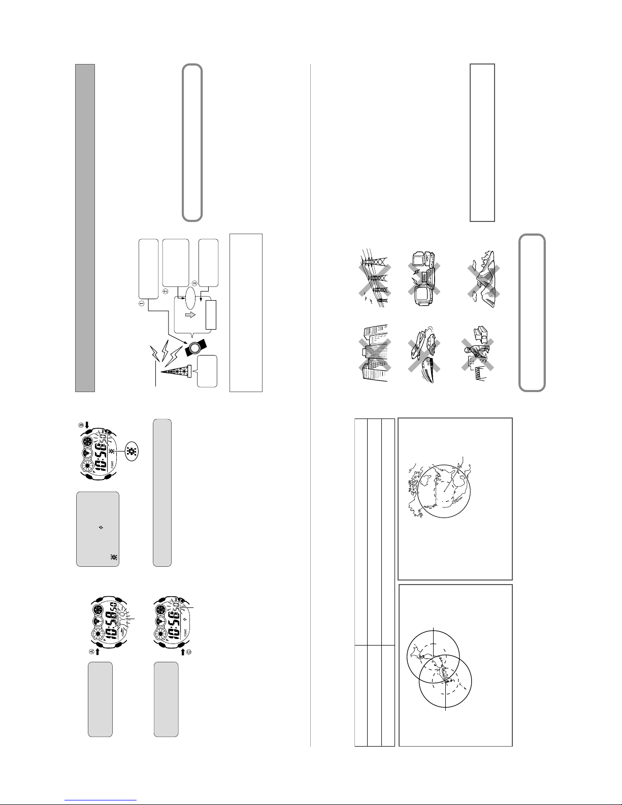
Near high-voltage linesAmong or near buildings
receive operation is performed again at 5:00.
performed at midnight, and at 1:00 and 2:00 in the morning.
• If both the 1:00 and 2:00 receive operations are unsuccessful, a
• If all five of the above receive operations are unsuccessful, a
Manual receive (You initiate reception using a button operation.)
Next to a household appliance
or office equipment (TV, speaker ,
fax, computer, cell phone, etc.)
The watch is set up for auto receive at the factory, so all you
need to do is to place it in a location that allows good
reception each night.
Near mountains
clock
How a Radio-controlled Watch Works
What is a radio-controlled watch?
Your radio-controlled watch is designed to receive a time
indicator)
BB
BB
B button to
indicator).
and 2.5 seconds
Press the
3.
(
toggle the illumination
duration between about
1.5 seconds (
Transmitter
calibration signal that contains standard time data, and adjust its
current time setting accordingly.
AA
AA
A
After the setting is the way you want, press the
button to exit the setting screen.
4.
Home City Code
atomic
Cesium
do not perform any operation for about two or three minutes.
• The watch will also exit the setting screen automatically if you
Seconds
(3 times)
After the watch receives the Standard Time signal, it performs
internal calculations to determine the current time. Because of
this, there may be an error of up to one second in the
displayed time.
Location
is receiving the calibration signal.
Reception is difficult and may even be impossible in the locations
described below. Avoid such locations when performing signal
reception.
• You should think of your watch operating like a radio or TV when it
Transmitter
U.S. Transmitter
Location
Either the Mt. Otakadoya signal (40kHz) or the Mt. Hagane signal (60kHz)
Fort Collins, Colorado signal
1000km
Inside a vehicle
(automobile, train, plane, etc.)
Fort Collins
3000km
1000km
(40kHz)
Mt. Otakadoya
500km
If you are experiencing problems with reception, move away
from the types of locations described above to a location with
In a location where there is
radio interference
receivable up to 3,000 kilometers from the transmitter. Note
that the wave is relatively weak at distances greater than
1,000km, so reception may be poor at long distances.
• Under optimum conditions, the calibration signal should be
1000km
better reception, and try again.
(construction site, airport, etc.)
AA
AA
A for about
In the Timekeeping Mode,
hold down
two seconds.
City code to flash on the
■ To specify the illumination duration
• This will cause your Home
1.
CC
CC
C button three
Press the
times to display the
display.
flashing seconds count.
2.
Reception Range
This watch is designed to receive the standard time calibration signal of Japan (JJY) or of the United States (WWVB). The signal that is
received depends on the current Home City setting.
— 4 —
Japan Transmitter
Locations
500km
(60kHz)
Mt. Hagane
receivable up to 1,000 kilometers from the transmitter. Note
that the wave is relatively weak at distances greater than
500km, so reception may be poor at long distances.
• Under optimum conditions, the calibration signal should be
range of the transmitter.
• Geographic contours, nearby buildings, seasonal conditions, the time of day, can even make reception impossible even when you are within
• Best reception is possible late at night.
TYO, SEL
Home City
LAX, DEN, CHI, NYC
City Code List”.
• For information about selecting a Home City, see “Configuring Home Time Settings”. For information about city codes, see the “World Time
Page 7
DD
DD
D button.
reception date screen and the last reception time screen at two-
second intervals.
able to perform any signal reception successfully.
In the Timekeeping Mode, press the
■ To view the last reception date and time
• This causes the display to start alternating between the last
Receive Indicator
■ Receive Indicator
The receive indicator cycles from
“Unstable” through “Stable” as
shown below while reception is in
progress. How far it cycles depends
on the signal strength. Keep the
you do not perform any operation for about two or three minutes.
• “– – –” will appear in the digital display if the watch has not been
• To return to the Timekeeping Mode, press the D button again.
• The watch will return to the Timekeeping Mode automatically if
Stable
Unstable
White-On-
watch in a location where reception
Black
is stable while reception is in
progress.
2 seconds
Last reception
date
seconds for reception to stabilize.
Black-On-
White
• Even under optimum reception conditions, it can take about 10
Last reception
time
determine the best location for signal reception.
factors can all affect reception.
• Use the receive indicator to check reception status and to
• Note that weather, the time of day, surroundings, and other
Timekeeping Mode or World Time Mode only.
Calibration Signal Reception
Precautions
• Auto reception can be performed while the watch is in the
• AUTO
Auto Receive Settings when the Home City is TYO
or SEL
progress.
the watch to beep and then exit the receive operation.
transmitter before performing the reception operation. Remember
that geographic contours, nearby buildings, seasonal conditions,
the time of day, can even make reception impossible even when
you are within range of the transmitter.
the signal. If reception is unsuccessful, try again.
accordance with the calibration signal transmitted in Japan and
the United States only. It operates like a standard (non-radio
controlled) watch outside of the range of the receivable time
calibration signal transmitters.
calibration signal for some reason, timekeeping accuracy is within
±15 seconds per month.
• Reception cannot be performed while Timer Mode countdown is in
• Pressing any button while auto reception is in progress will cause
• Make sure you are within the range of the calibration signal
• Proper reception may be impossible if there is something blocking
• This watch is designed to adjust its current time setting in
J40
J60
Auto receive turned on for the Mt. Otakadoya signal (40kHz).
Auto receive turned on for the Mt. Hagane signal (60kHz).
Mt. Otakadoya signal (40kHz) or the Mt. Hagane signal
(60kHz), whichever is strongest.
Auto receive turned on with automatic selection of either the
•
Auto receive turned off.
•
• OFF
Auto Receive Settings when the Home City is NYC,
CHI, DEN, or LAX
being performed.
• When the watch is unable to adjust its time signal using the
• Strong electrostatic charge can cause timekeeping error.
• Signal reception is cancelled if the alarm starts to sound while it is
Auto receive turned on for the Ft. Collins, Colorado signal.
• OFF
• ON
Attempting a receive operation after that causes an error.
• The watch’s calendar shows dates up to the year 2099.
Auto receive turned off.
DD
DD
DD
DD
D button for about
reception will start. An indicator
down the
two seconds.
• The watch will beep and
will appear on the display to
In the Timekeeping Mode, hold
■ To perform manual receive
D button.
indicate reception conditions.
Press the
• All other buttons besides D are disabled during signal reception.
When reception is successful
■ To interrupt reception
Resin band
The watch terminates reception and adjusts the current time. Next
it beeps and then displays the date and time that the adjustment
reception
approximately in the direction of the signal transmitter. Keep the
■ To position the watch for optimum
watch away from metal objects.
Remove the watch from your wrist and place it somewhere so its
top (12 o’clock side, where the antenna is located) is facing
BB
BB
B buttons
DD
DD
D and
press the D button or if you do not perform any operation for
about two or three minutes.
was performed.
• The watch will return to the Timekeeping Mode screen if you
Metal band
• Orienting the watch so it is sideways to the transmitter makes it
press the D button or if you do not perform any operation for
Reception Error (ERR Indicator)
more difficult to receive the signal.
about two or three minutes.
The watch does not adjust its current time setting, and displays
“ERR” when signal reception is unsuccessful for some reason.
• The watch will return to the Timekeeping Mode screen if you
transmitter selection mode, signal reception can take up to
• Do not move the watch while it is receiving the calibration signal.
■ Time Required for Reception
12 minutes.
A calibration signal receive operation takes anywhere from about
two to five minutes.
• Note that when “AUTO” (Auto Select) is specified as the
Use the
3.
• See “Configuring Auto Receive Settings” for more information.
Configuring Auto Receive Settings
— 5 —
AA
to cycle through the
available auto receive
settings.4.When the setting is the
Use the procedure below to turn auto receive of the time
calibration signal on or off. When TYO (Tokyo) or SEL (Seoul) is
selected as your Home City, you can also specify the transmitter
selection mode, which controls which Japanese transmitter signal
should be used for time calibration.
• For information about selecting your Home City, see “Configuring
AA
way you want, press the
A button.
screen and return to the last
reception date and time
screens.
Mode, press the D button
• This will exit the setting
NYC, CHI, DEN, or LAX is selected as the Home City.
Home Time Settings”.
TYO (Tokyo); Auto Receive = On; Transmitter = AUTO
• The initial factory default settings for auto receive are Home City =
• The following procedure can be performed only when TYO, SEL,
■ To configure auto receive settings
again.
• To return to the Timekeeping
• The watch will return to the
DD
DD
D button.
In the Timekeeping Mode,
press the
start alternating between the
last reception date and time
• This causes the display to
1.
Timekeeping Mode
automatically if you do not
perform any operation for
about two or three minutes.
screens.
Timekeeping Mode
automatically if you do not
perform any operation for
about two or three minutes.
• The watch will return to the
AA
AA
A button
Hold down the
for about two seconds.
auto receive setting to flash
on the display.
• This will cause the current
2.
Page 8

Tokyo
Auto Japan transmitter select
(40kHz/ 60kHz)
will display the date and time that the time calibration signal was
last received successfully. To return to the Timekeeping Mode,
press the D button again. See “To view the last reception date
and time” for more information.
problems with signal reception or when the time setting produced
by signal reception is incorrect.
are shown below. You do not need to change these settings if you
use the watch in Japan.
Auto Receive
• Check the auto signal reception setting whenever you have
How can I view the last reception date and time?
• In the Timekeeping Mode, press the lower right D button. This
• The initial factory default configuration of the reception settings
Home City
Auto switching in accordance
with signal data
Summer Time
Kabul
Dubai
Jeddah
City Name
Jerusalem
+2
+3
GMT
Differential
JRS
JED
City
Code
Honolulu
City Name
GMT
–11
–10
Differential
City
HNL
– – –
Code
World Time City Code List
Karachi
Teheran
+3.5+4+4.5+5+5.5+6+6.5
KHI
KBL
THR
DXB
Denver
Chicago
Anchorage
Los Angeles
–9–8–7–6–5–4–3–2–1
CHI
L AX
ANC
DEN
DST Indicator
BB
BB
B buttons
DD
DD
D and
Delhi
DEL
New York
NYC
Dakar
Yangon
DAC
RGN
Caracas
Rio de Janeiro
RIO
CCS
AA
AA
A button
Bangkok
Hong Kong
+7+8+9
BKK
HKG
– – –
– – –
Seoul
Tokyo
Sydney
Adelaide
+9
+10
+9.5
SEL
ADL
TYO
SYD
Paris
Berlin
London
Greenwich Mean Time
+0+0+1+1+2
PAR
LON
BER
GMT
Noumea
Wellington
+11
+12
NOU
WLG
Cairo
Athens
+2
Universal Time Coordinated (UTC).
CAI
ATH
• The contents of the above table are current as of June 2004.
• Time differentials in the above table are in accordance with
unless TYO (Tokyo), SEL (Seoul), NYC (New York), CHI
(Chicago), DEN (Denver), or LAX (Los Angeles) is selected as the
Home City. Use the procedure under “Configuring Home Time
The auto receive ON/OFF settings don’t appear when
configuring auto receive settings.
time signal and current time are slightly off.
Time calibration signal reception is successful, but the hourly
Settings” to select your correct Home City.
• Auto receive ON/OFF settings do not appear on the display
internal decoding process before updating its time setting.
Because of this, the time setting may be slightly off (within one
second).
• After the watch receives the time calibration signal, it performs an
available only when TYO (Tokyo) is selected as the Home City
code. Use the procedure under “Configuring Home Time Settings”
to select your correct Home City.
reception conditions are best. Before going to bed at night, place
the watch near a window, with its 12 o’clock position facing in the
when configuring auto receive settings.
• The AT, J40, and J60 transmitter selection mode options are
The auto receive AUTO, J40, and J60 settings do not appear
procedure under “Configuring Home Time Settings” to turn off
summer time.
Time calibration signal reception is successful, but the current
time is one hour fast.
• Do you have summer time (DST) turned on (ON)? Use the
Time calibration signal reception is successful, but the current
time setting is wrong.
general direction of the transmitter.
What time is auto receive performed?
• Auto receive is performed in the middle of the night, when
How can I perform manual receive?
If you are in Japan, you should have TYO selected for your Home
City. For other areas, select the correct Home City code using the
procedure under “Configuring Home Time Settings”.
• Is the correct city code selected for your Home City?
watch will beep to indicate that manual receive has started. Place
it near a window, with its 12 o’clock position facing in the general
• Hold down the lower right D button for about two seconds. The
direction of the transmitter.
Using Summer Time (DST)
Summer time, or Daylight Saving Time (DST) as it is known in
some countries, calls for setting clocks ahead one hour during the
summer season. Note that the use of summer time depends on
the country and even the local area.
■ To turn summer time on or off
BB
BB
B
DD
DD
D (westward) or
To search for a city code
In the World Time Mode, press the
(eastward) button.
■
use the
to display the screen for
the city code whose
summer time setting you
1. In the World Time Mode,
(Eastward)
• This scrolls the available city codes.
• Holding down the B and D buttons scrolls at high speed.
for about two seconds.
want to change.
2. Hold down the
(Westward)
Current Time in
Selected City
• This toggles summer time on and off.
City Code
is advanced by one hour when summer time is turned on.
World Time Mode city. Note, however, that you cannot turn on
summer time for the “GMT” city code.
time shown in the Timekeeping Mode to be advanced by one
• The “DST” indicator appears on the display and timekeeping
• You can turn summer time on or off independently for each
hour.
• Turning on summer time for your home time city causes the
Though the Japanese calibration signal (Call Sign: JJY) is
Troubleshooting
The watch cannot receive the time calibration signal.
• Is the signal being transmitted?
See “Reception Range” for information about areas where the
continually transmitted by the National Institute of Information and
Communications Technology (NICT) in theory, it may sometimes
be interrupted for periodic maintenance work, or because of
lightning or other problems.
Even if you are within the reception range of a transmitter, objects
watch can receive the signal.
with reception?
between you and the transmitter or electrical noise can interfere
with reception. Avoid such areas during signal reception. See
• Are you within the reception range of a transmitter?
“Location” for more information.
• Is there something in the immediate area that may be interfering
• Do you have the correct Home City code selected?
Remember that auto receive is not performed unless TYO
(Tokyo), SEL (Seoul) NYC (New York), CHI (Chicago), DEN
(Denver), or LAX (Los Angeles) is selected as the Home City.
Select the correct Home City code using the procedure under
“Configuring Home Time Settings”.
• Is auto receive turned off (OFF)?
Auto receive is performed only when the watch is in the
Use the procedure under “Configuring Auto Receive Settings” to
turn on auto receive.
World Time Mode during the auto receive times (midnight, 1:00
a.m., 2:00 a.m., 3:00 a.m., 4:00 a.m., and 5:00 a.m.)?
Timekeeping Mode or World Time Mode. It is not performed if the
watch is in any other mode.
• Is the watch in any mode other than the Timekeeping Mode or
— 6 —
World Time Mode
was displayed when you last exited the mode appears first.
Timekeeping Mode seconds count.
Mode time is also applied in the World Time Mode.
settings in the Timekeeping Mode and the World Time city
World time lets you display the current time in any one of 30 cities
(29 time zones) around the world.
• When you enter the World Time Mode, the screen for the city that
• The seconds count in the World Time Mode is linked with the
• The same 12-hour/24-hour format you select for the Timekeeping
settings.
Important!
• If the World Time Mode time is incorrect, check the current time
• For more information, see “Configuring Home Time Settings”.
Page 9

DD
DD
D button to display the
Snooze Alarm
Snooze On Indicator
Alarm On Indicator
Clears split
time.
Reset
of 2nd finish.
BB
BB
B button to toggle the displayed alarm on
Alarm 1
In the Alarm Mode, use the
screen for the alarm you want to turn on or off.
Press the
(alarm on indicator displayed) or off (alarm on indicator
not displayed). Turning on the snooze alarm will cause
the “SNZ” indicator to appear on the display.
■ To turn an alarm on and off
1.
)
Decrease
(
BB
BB
B(–)
DD
DD
D (+) and
Use the
buttons to change the
4.
2.
(Increase)
currently selected digits.
changes the setting at high
speed.
Repeat steps 3 and 4 for the hour digits and the minute
• Holding down either button
digits to set the time you want.
correctly when using 12-hour timekeeping, or that you specify the
correct 24-hour time.
• When setting the hour, make sure you specify AM (A) or PM (P)
Alarm On Indicator
AA
AA
A
When the setting is the way you want, press the
button.
you do not perform any operation for about two or three
minutes.
• This exits the setting screen.
is also applied in the Alarm Mode.
• The same 12-hour/24-hour format you select for your home time
• The display also will exit the setting screen automatically if
5.
Split Time Display
Stop ResetStart
Record Split Release Split ResetStopStart
■ Elapsed Time Measurement
Stopwatch Mode
The stopwatch measures elapsed time in units of 1/100 second up
Cumulative Elapsed Time Measurement
Pressing the D button to restart the stopwatch without resetting it
to all zeros causes the elapsed time measurement to resume from
where it was last stopped.
■ Split Time Measurement
1/100
Second
(Split/Reset)
CC
CC
C button to start and stop
Minutes
dials appear and disappear to indicated the passage of time.
elapsed time measurement.
to 23 hours 59 minutes, 59.99 seconds (24 hours). When the
maximum limit is reached, the elapsed time automatically returns
In the Stopwatch Mode, press the
to zero and timing continues from there.
■ Performing Stopwatch Operations
• During elapsed time measurements, segments in the graphic
Split Indicator
■ 1st and 2nd Place Finishers
(Start/Stop)
Seconds Hours
freezes the current elapsed time on the display and
displays the “SPL” (split) indicator, while elapsed timing
continues internally.
• Pressing the B button while timing is being performed
2nd finish Displays time
(Displays time
of 1st finish.)
Start 1st finish
clears the split time.
stopped resets the stopwatch to all zeros.
• Changing to another mode while a split time is displayed
• Pressing the B button while elapsed time measurement is
Minutes
Hour
AA
AA
A button
Hold down the
for about two seconds
until the hour digits start
to flash on the display.
2.
Using the Alarm and Hourly Time Signal
Alarms
■ Daily Alarms (AL1 to AL4)
The watch beeps for about 10 seconds when an alarm time is
Alarm on indicator
Hour
CC
CC
C button to
indicator to appear and
automatically turns on the
alarm.3.Use the
• This also causes the alarm on
reached.
■ Snooze Alarm (SNZ)
With the snooze alarm, the watch beeps for 10 seconds when the
select the digits you want
to change.
moves the flashing between
the hour digits and minute
digits.
• Each press of the C button
(Next alarm)
Alarm Number
DD
DD
In the Alarm Mode, use the
D button to scroll
through the alarm screens
until the one whose
setting you want to
change is displayed.
alarm time is reached, and up to seven times at five-minute
intervals thereafter (approximately 30 minutes total). Pressing any
button stops the beeper, but the alarm will sound again after five
minutes.
■ To set an alarm time
1.
(AL3)
Alarm 3
(AL2)
Alarm 2
(AL1)
Alarm 1
Hourly Time Signal
The hourly time signal causes the watch to beep twice every hour
on the hour.
(AL4)
Alarm 4
(SNZ)
Snooze Alarm
Hourly Time
Signal (SIG)
■ To stop the alarm beeper
Press any button.
• In the case of the snooze alarm the alarm will sound again in
about five minutes. “SNZ” flashes on the display during the
DD
DD
D button to display the
BB
BB
B button to toggle the hourly time signal on
In the Alarm Mode, use the
hourly time signal screen.
Press the
or off.
■ To turn the hourly time signal on and off
1.
2.
• If you turn off the snooze alarm
• If you display the snooze alarm setting screen
five-minute period between snooze alarms (indicating that the
• If you display the Timekeeping Mode setting screen
alarm will sound again).
following occurs while the SNZ indicator is flashing on the display.
• The snooze alarm will be canceled automatically when any of the
■ To test the alarm
Hourly Time Signal Screen
indicator to appear on the display. The watch will beep twice
every hour on the hour.
• Turning on the hourly time signal causes the hourly time signal
In the Alarm Mode, hold down the D button to sound the alarm.
Hourly Time Signal
On Indicator
— 7 —
Page 10

CC
CC
C button to
12/24-hour
Timekeeping
Summer Time
Seconds
Hour
Minute
Month Year
■ End of Countdown
The watch beeps for 10 seconds when the end of the countdown
is reached.
■ To stop the time up beeper
Press any button while the beeper is sounding to stop it.
1/10 second
DD
DD
D button.
In the Timer Mode, press the
■ Using the Timer
dials appear and disappear to indicated the passage of time.
• Each press of the D button starts or stops the countdown.
• The timer counts down in 1/10 second units.
• During elapsed time measurements, segments in the graphic
(Reset)
Seconds
Minutes
(Start/Stop)
resets the display to the start time.
• Pressing the B button while the countdown is stopped
• Pressing the D button again while the timer countdown is
stopped restarts the countdown.
setting is the way you
want, use the
cycle the display through
the settings shown below.
5. When the summer time
DD
DD
D button to
cycle through the
available summer time
(DST) settings until the
one you want to select is
displayed.
4. Press the
)
Eastward
(
Code
Home City
This setting enables the auto summer time setting, which
turns summer time on or off in accordance with the received
time calibration signal.
• This setting uses Japan summer time data when TYO is
• A (AUTO)
(Westward)
TYO = Tokyo
Day
Power Saving
is selected as the Home
f summer time and returns to normal
City.
selected as the Home City, and U.S. summer time data
when NYC, CHI, DEN, or LAX
This setting turns of
timekeeping.
• OF (OFF)
• On (ON)
This setting turns on summer time and advances the current
time by one hour.
a setting other than HKG, TYO, SEL, NYC, CHI, DEN, LAX, ANC,
• Only OFF or ON can be selected if the current Home City code is
or HNL.
AA
AA
A
you want, press the
button.
setting screen automatically if
you do not perform any
operation for about two or
• This exits the setting screen.
3. After start time is the way
Timer Mode
You can set the start time of the time in the range of 1 to 60
minutes, in units of one minute. The watch beeps for 10 seconds
when the end of the countdown is reached.
■ To set the timer time
three minutes.
• The watch will also exit the
AA
AA
A for about two
down
seconds.
digits of the timer start time to
• This will cause the minute
1. In the Timer Mode, hold
Minutes
flash.
(Back)
BB
BB
B (–)
DD
DD
D (+) and
buttons to change the
start time.
scrolls the start time setting at
• Holding down either button
2. Use the
(Forward)
high speed.
range of 1 minute to 60
minutes.
• You can set a start time in the
— 8 —
BB
BB
B
DD
DD
D (westward)
CC
CC
Code List” for information
button and the
(eastward) button to scroll
through the city codes
2. Use the
Configuring Home Time Settings
Home time settings include your Home City (the city where you will
normally use the watch), the current time and date in your Home
City, and other settings.
• Use the Timekeeping Mode to configure home time settings.
• Also use the following procedure when you want to turn Power
about city codes.
until the one you want to
select is displayed.
Saving on or off.
• Holding down either button
• See the “World Time City
AA
AA
A button
hold down the
for about two seconds.
■ To configure home time settings
1. In the Timekeeping Mode,
C button.
scrolls at high speed.
want is displayed, press
the
• This will display the summer
3. When the city code you
Home City Code
currently selected as the
Home City to flash on the
display.
• This will cause the city code
time (DST) setting screen.
Page 11

AA
AA
When all of the settings are the way you want, press the
A button.
you do not perform any operation for about two or three
minutes.
• This exits the setting screen.
• The display also will exit the setting screen automatically if
10.
(Back)
Minutes
DD
DD
D (+)
BB
BB
B (–) buttons to
While the hour, minutes,
year, month, or day setting
is flashing, use the
and
change the setting.
8.
• Holding down either button
DD
DD
D
(Forward)
Hour Year
changes the setting at high
speed.
sure you specify AM (no
indicator) or PM (P) correctly,
or that you specify the correct
24-hour time.
• When setting the hour, make
.
Indicates 12-hour or
24-hour timekeeping
the week is set automatically in accordance with the date you
• You can set a year in the range of 2000 to 2099. The day of
DD
DD
D
DD
DD
set.
• The watch automatically makes adjustments for leap years
Resets to 00.
D button to toggle it
and month lengths.
While the Power Saving
setting is flashing, press
the
9.
on (ON) or off (OF).
the Power Saving indicator
will be on the display when
you exit the setting screen.
• If you turn on Power Saving,
Use the C button to select each of the settings and the D and
B buttons to change them.
While the 12/24-hour
timekeeping setting is
flashing, press the
button to toggle between
12-hour (“12H”) and
24-hour (“24H”)
timekeeping.7.While the seconds are
6.
selected, press the
button to reset them to 00
in accordance with the
time signal on the radio,
TV, etc.
the seconds count is in the
range of 30 to 59 resets it to
• Pressing the D button while
00 and also adds 1 to the
minutes. Pressing the D
button in the range of 00 to 29
resets the seconds count
without changing the minutes.
the seconds count is flashing
changes the display
illumination duration. See “To
• Pressing the B button while
specify the illumination
duration” for more information.
— 9 —
Page 12

3. DRAWINGS: MODULE QW-2914
3-1. LCD DIAGRAM
W9
W0
W8
W1
HIGH
anta2
PM
W7
W2
MID
W6
W3
W5 W4
DST
a5
b5f5 b2f2
g5
c5e5
a4 a3
f4
b4
g4
e4 e2
c4
hyp
min
f3
g3
e3 c3
col0
d5
RECOVER
d4
d3
SPL1
y4
PSAVE
y0
x0
b3
LCHARGE
a2
g2
d2
c2
anta1
x16
sec
SIG
f1
e1
a1
g1
c1
d1
AUTOEL
anta0
b1
SNZ
ALM
a0
f0 b0
g0
c0e0
d0
L25
L26
L27
L28
L29
L30
LC3
LC1
LC2
COM
L 1
L 2
L 3
L 4
L 5
L 6
L 7
L 8
L 9
L10
L11
L12
L13
L14
L15
L16
b1
g1
b2
c1
e1 f1
g2
d1 anta2
c2
f2
b3
f3
b4
f4
b5
c3
g3
g4
e4
c5
g5
x16y2
x15y2
x16y3
x15y3
x14y2 x14y0x14y3
x13y2 x13y1
d3
e3
c4
d4
d5
e5
x16y4
x15y4
x14y4
x13y4
x12y2 x12y1x12y0x12y3 x12y4
x11y2
x11y3 x11y4
L17
L18
L22
L23
L24
anta1
anta0
MID
HIGH
hyp
RECOVER
SPL1
AUTOEL
DST
x16y0
x15y0
x13y0x13y3
x11y0
x10y0x10y4x10y2f5x10y3 x10y1
L21
COM
COM
LC1 LC2 LC3 LC4LC1 LC2 LC3 LC4 LC5
x8y2
x7y2
x6y2
x5y2
x4y2
x3y2
x2y2
x1y2
x0y2
f0
b0
W7
L30
PSAVE
LCHARGE
x8y3 x8y1
x7y3
x6y3 x6y1x6y0
x5y3
x3y3
x2y3
x1y3
x0y3
g0
c0
W1
W8
a1
sec
a2e2 d2
a3
col0
min
a4
a5
PM
x16y1
x15y1
x14y1
x11y1
SEGSEG
L19
L20
L21
L22
L23
L24
L25
L26
L27
L31
L32
L33
L34
SEG
L28
L29
L 1
x8y4
x7y4
x6y4
x4y4x4y3
x2y4
x1y4
x0y4
L31
e0
d0
W0W2
W9
L 2
L 3
L 4
L 5
L 6
L 7
L 8
L 9
L10
L11
L12
L13
L14
L15
L16
L17
L18
L19
L20
L32
L33
L34
LC5
x8y0
x5y0x5y4
x4y0
x3y0x3y4
x2y0
x1y0
x0y0
ALM
SNZ
W4
W5 W6
LC5
x7y1x7y0
x5y1
x4y1
x3y1
x2y1
x1y1
x0y1
SIG
a0
W3
LC4
x9y1x9y3x9y2 x9y4 x9y0
— 10 —
Page 13

3-2. CIRCUIT DIAGRAM
ANT
✽15
Crh1
RP1RP2
Crh2
Crh3
✽13
Crl1
Cp
✽13
Crl2
✽13
Crl3
P14
Hold
P3-2
Pon
Asel
GND4
Rpd
✽14
Ccp
Rcp
✽17
P9
TCO
VCC
P12
P13
✽17
P7
GND1
ISB
P1
P2
FET-D
Cc
✽13
FET-S
Rxt2
Xtal2
✽13
Rxt3
✽13
Xtal3
✽12
Cxt
GND5
P5
P4
✽17
P3-1
GND2
GND3
✽2
✽2
Cbat
Rbat
modules without signal reception function.
✽ 16. This PKG can be used with both EL and LED, and the one which is not
used is not mounted.
✽ 17. As P3-1, P3-2 and VCC are connected inside ISB, any one of them
for single transmitter.
✽ 14. Rpd is mounted only in the specification which does not include signal
reception.
✽ 11. KC3 is used in this module.
✽ 12. Cxt is not mounted in the specification for dual translmitters.
✽ 13. Cc, Crl1, Crl2, Crl3, Rxt3 and Xtal3 are not mounted in the specification
✽ 15. No parts except Rdp are mounted within the area of the dotted line in
should be connected to the wiring of Rbat-Cbat.
SCR
SCIN
✽1
✽1 ✽1
SDO SCK CSB
✽1
SDI
L36L35
✽8
LCD ( 2.8V 1/3b 1/5d )
L1 - - - - L34 LC1 - - - - - LC5
T1T2T3
AC
KI1
KI2
KI3
T4
SA
S2
S1
S3
KC4
KC3
KC2
VPM
✽1
LSI
TOTAL 106PINS
BONDING 82PINS
✽3
✽3
✽3✽3✽3
✽3
KI4
KI5
KI6
KI7
KI8
KI9
N1
S4
SK
✽5
✽2
KS
✽6✽6✽4✽4✽4
✽3
R2
R3
N2
R1
✽10
XTB
Xtal
KC1
✽11
XT
CT
✽9
LD1
VDD1
VDSP
VCH VDD3 VC1 VC2
VHF
VC3 VC4
BD
GND VDD2
VSC
C3
C2C5
C1
C4
C6
C7
LL1
Tr1
R1
Di2
PZ
Z
BAT
C8
Di1
SC
C9
✽ 1. No bonding
✽ 2. Kl7-GND: Open (No Soldering)
Kl6-KC1: Open (No Soldering)
Kl6-KC3: Open (No Soldering)
✽ 3. Latch type key
✽ 4. Short (Soldering) (R trimming)
✽ 5. Inclination sensor
✽ 6. Short (Soldering) (N trimming)
✽16
EL
BACK
FRONT
LL2
NCNCNC
VCC
ENB
GND
ELD
INV
RT1
CIL
Rld1LED1
RT2
Rel
Tr2
✽ 7. GNDB is used for the bias on the back of the tip.
✽ 8. L28~L30 are used as the static drive pins.
✽ 9. Normal Low
✽ 10. LD2 (Normal Low) is used in this module.
LED2 Rld2
— 11 —
✽7
GNDB
Rb
Page 14

3-3. CHECKING TERMINALS AND COMPONENTS
1-chip type (pre-change)
LEDOUT
Short pad for switching modules
Short pad for R trimming
Short pad for N trimming
LD1 GND
KI1
GND
R3
GND
SCIN
KI4
R2GND
R1GND
GND
SCR
SCIN
SCIN
GND
N2
GND
N1
GND VSC
GNDB
LEDOUT
VDD2R1VDD2 R2
R1
LEDOUT R2
KI9GND
GNDKI8
GND KC3
KI7
KC1
KI6
KI6
KI5
12a. PCB ASS'Y
(7640 8263)
BD
R1
GND
VSC VDD2
KI2
KI3
SENSOR/TILT
CUSHION 6
OSCILLATOR/CRYSTAL
CAPACITOR/TRIMMER
CUSHION 506
VDSP
P1
FET-S
KI8
VCHGND
GND
VC3
VC2
KI5
GND
VDSP
VHF
GND
VDD3
GND
VDD1
GND
KI3
VC1
VC4
VC1
GND
VCH
XT
XTB
XT
GND
GN
D
AC
LL
1
LL1
VDD2
GND
LL1
LL1
R1
GND
KI2
VDD2
R1
VDD2
KI2
FET-D
P2
P2
GND
VDD2
P12
P14
P13
KI9
GND
P9
P4
VCC
VCC
Rcp
Rcp
Rxt2
VDD2
Rxt3 P5 P7P5
GND
VDD2
Rxt3
Rxt2
BD
ELD
CIL
LD
D
E
GN
DD2
CIL
VSC
V
KI1
P7
RT2
P7
1
T2
D
T
R
1
R
D
GN
DD2
L
V
RT1
LD1
KI4
D
GND
GN
CUSHION 506
— 12 —
Page 15

2-chip type (post-change)
LEDOUT
LD1
Short pad for switching modules
R1
VDD2
GND
R1
LEDOUT
LEDOUT
R2
R2
VDD2
GND
KI8
Short pad for R trimming
Short pad for N trimming
SENSOR/TILT
CUSHION 6
OSCILLATOR/CRYSTAL
CAPACITOR/TRIMMER
KI1
KI6
KC3
GND
GND
R3
GND
GND
SCIN
GND
VSC
KI4
R2
GND
GND
R1
SCIN
SCR
GND
SCIN
N2N1GND
GND
ELD
12b. PCB ASS'Y
(7641 0226)
VSC
VSC
GNDB
VDD2
KI2
KI6
KC1
KI9
KI7
GND
GND
KI5
VC4
VC3
VHF
GND
KI3
VDD2
CUSHION 6
1
S2
KI8
16 12
GND GND
GND
GND
KI5
VC1
VC1
VC2
GND
VDD3
GND
GND
VDSP
VDD1
VDSP
KI3
VCH
GND
XTB
XT
XT
GND
G
N
D
AC
GND
VCH
GND
13
VDD2
VDD2
D
2
GND
3
3
14
3
S
D
GND
Rcp
9
GND
GND
D
G
KC2
S
GND
KC2
G
7
t3
Rxt3
x
R
RT1
RT2
IL
C
OSCILLATOR/CRYSTAL
KI1
2
t
x
R
7
575
Rxt2
4
2
RT2
1
ND
RT1EL
D
G
L
VDD
VDD2
KI4
D
ND
ND
G
ND
G
G
CUSHION 506
LL1
LL1
LL1
GND
LL1
K12
BD
R1
R1
VDD2
VDD2
R1
VDD2
K12
VDD2
VSC
IL
C
— 13 —
Page 16

4. EXPLODED VIEW: MODULE QW-2914
16 (1017 2600)
19 (1010 6532)
9 (1017 2597)
11 (1016 9827)
7 (1017 2603)
19 (1010 6532)
20 (7210 9058)
1-chip type : 15a (1017 2599)
2-chip type : 15b (1022 1067)
18 (7230 1045)
4 (1008 3365)
2-chip type : 21 (1022 1111)
1 (1006 5657)
Battery storage (CTL1616)
10 (1006 5664)
1-chip type : 12a (7640 8263)
2-chip type : 12b (7641 0226)
PCB ass'y
8 (7231 1777)
13 (1012 3230)
3 (1016 8959)
17 (7201 9599)
— 14 —
Page 17

5. PARTS LIST: MODULE QW-2914
-
s
p
p
p typ
p typ
Note: 1. Prices and specifications are subject to change without prior notice.
2. Spare parts are classified as follows according to their importance in after-sales service.
A Rank ---------------------------------------- Very Important
B Rank ---------------------------------------- Important
C Rank ---------------------------------------
3. Batteries in Bulk pack on the tray will be supplied from our Overseas Spare Parts Section under charge basi
Batteries in Blister pack will be supplied from our Sales Department.
4. As for order/supply of spare parts, refer to the separate publication "GUIDE BOOK for spare parts supply".
Less important
Item Code No. Parts Name S
7640 8204 MODULE/WITH MOVEMENT QW-2914YC-01TK GW-002J-8A 1 A
1006 5657 BATTERY/STORAGE CTL1616 QW-2914YC-01TK 1 B
1
1009 7666 CAPACITOR/TRIMMER CTZ2E-25C-W2-P QW-2914YC-01TK 1 B
2
1016 8959 CONTACT/BATTERY 2730 Q255819-2V05 QW-2914YC-01TK 1 C
3
1008 3365 CONTACT/BATTERY(-) 1673 Q358740A-2 QW-2914YC-01TK 1 C
4
7211 0064 CUSHION 6 Q4914A-1 QW-2914YC-01TK 1 C
5
7211 9631 CUSHION 506 Q49364-1 QW-2914YC-01TK 2 C
6
1017 2603 EL YEL-2914-A-00 QW-2914YC-01TK 1 A
7
7231 1777 HOLDER 1381 Q456843-1 QW-2914YC-01TK 1 C
8
1017 2597 INTERCONECTOR/ 2914 RJQ521721-001V01 QW-2914YC-01TK 1 C
9
1006 5664 LABEL/ 2368 Q468543A-1 QW-2914YC-01TK 1 C
10
1016 9827 LCD S2914-01THP QW-2914YC-01TK 1 A
11
1012 3230 SCREW/FLAT2730 RJQ513792-001V01 QW-2914YC-01TK 1 B
13
7105 5275 SENSOR/TILT TS-2418-P QW-2914YC-01TK 1 B
14
1017 2600 SPACER 2914-1 RJQ522168-001V01 QW-2914YC-01TK 1 C
16
7201 9599 SPRING/COIL 967-1 Q430081-1 QW-2914YC-01TK 1 B
17
7230 1045 SPRING/COIL 2017-1 Q462959-1 QW-2914YC-01TK 2 B
18
1010 6532 SPRING/COIL 2611-1 Q470669A-1 QW-2914YC-01TK 2 B
19
7210 9058 POLE Q430269A-1 QW-2914YC-01TK 1 C
20
1-chi
12a
15a
e
7640 8263 PCB ASS'Y RJQ522663*001V01TK QW-2914YC-01TK 1 A
1017 2599 SPACER 2914 RJQ521942-001V02 QW-2914YC-01TK 1 C
ecification Applicable Q R
2-chi
12b
15b
21
e
7641 0226 PCB ASS'Y RJQ529876*001V01TK QW-2914YC-01TK 1 A
1022 1067 SPACER 2914-2 RJQ529592-001V02 QW-2914YC-01TK 1 C
1022 1111 HOUSING RJQ529593-001V03 QW-2914YC-01TK 1 C
For the
Notes: Q - Used quantity
rices and minimum order/supply quantities of the above parts, refer to the Parts Price List P.P.L.-616.
R - Rank
— 15 —
Page 18

6. PRECAUTIONS FOR REPAIR: MODULE QW-2914
6-1. AC (ALL CLEAR) AND REMOVING OF MODULE
1. Perform AC (ALL CLEAR) when inserting a new battery, or else the memories and/ or counters may give
erratic displays.
Touch the AC contact and the main plate with the metallic tweezers.
The contact should be made for about two seconds.
2. On removing of the module from the case, please insert the precision screw driver between the module
and the case pointed by arrows.
6-2. ACCURACY CHECKING
Check the accuracy of the module with the quartz timer after switching the module to “ACCURACY
CHECKING MODE”.
The operations are shown below:
A) SWITCHING TO “ACCURACY CHECKING MODE”
While pressing the A button, press C and D buttons at the normal timekeeping mode.
Then all the segments are displayed and the LCD drive signals are changed to the static drive signal
of “32 Hz” so that you can check the accuracy with the quartz timer.
B) CANCELLATION OF THE “ACCURACY CHECKING MODE”
Press any button.
Then the display is returned to its original state.
NOTE: The “ACCURACY CHECKING MODE” will
automatically return to the regular mode
in 1 ~ 2 hour(s) without any operation.
— 16 —
A
C
B
D
L
QW-2914
Page 19

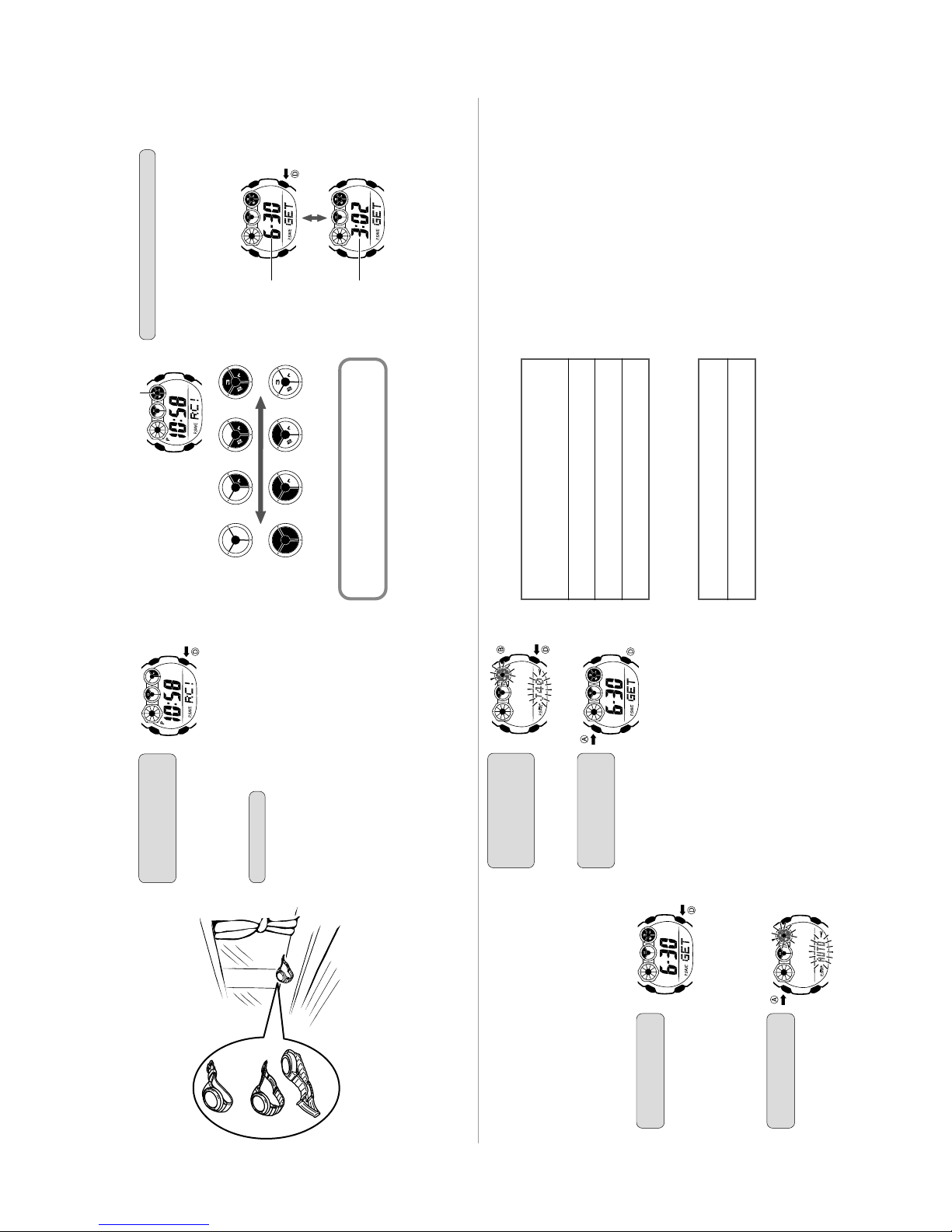
6-3. SOLAR CELL-PCB ASS'Y CONTACT CHECKING
Check a Solar cell and PCB ass'y are contacted correctly by contact spring, when a module is
disassembled.
1. To enter TEST mode.
1) While pressing D button, press A and B buttons at the normal timekeeping mode.
2. Check a Solar cell and PCB ass'y contact in the following order.
1) Display side up and place the watch on the desk.
2) Check the display indicates as figure 2.
3) Display side down and place the watch on the desk more than 3 seconds.
Or go to a dark room and place the watch more than 3 seconds.
4) Check the display indicates as figure 3.
If “8888” is not appeared on the display, disassemble again the module and check the contact spring
between the Solar cell and PCB.
A
B
Press D, A and B buttons
C
D
Figure 1 Figure 2
Appear “8888” on display.
3. To exit from TEST mode
Press any button.
6-4. HOW TO CHECK TILT SENSOR
1) Press A, B and C buttons at the normal timekeeping mode.
2) Check the display indicates as figure 4.
3) Tilt the watch towards you more than 40 degrees.
4) Check the display indicates as figure 5.
Appear “TLT” on display.
Place the watch in a dark
room more than 3 seconds.
Figure 3
Appear “8888” on display.
Figure 4 Figure 5
Tilt the watch towards you
more than 40°
More than 40°
— 17 —
Page 20

7. TROUBLESHOOTING FOR TIME RECEPTION: MODULE QW-2914
START
Check whether the Home City
code is selected correctly.
Perform MANUAL time
calibration signal reception
Signal
reception OK?
No
Perform AUTO time
calibration signal reception
Signal
reception OK?
No
Replace the PCB ass'y
Signal
reception OK?
Yes
OK
Yes
OK
Yes
OK
There is a possibility of the bad location for reception.
No
Replace the Case center
ass'y with antenna
Signal
reception OK?
No
— 18 —
Yes
OK
Page 21

8. CHANGES TO THE PCB ASS'Y
Starting from the June 2006 production run, a change was made to the PCB ass'y.
(1-chip type → 2-chip type, as shown below)
LEDOUT
LD1 GND
LEDOUT
KI1
GND
R3
R2GND
GND
R1GND
SCIN
SCR
GND
SCIN
SCIN
GND
N2
GND
N1
BD
GNDB
KI4
GND
R1
GND VSC
VSC VDD2
R1
VDD2R1VDD2 R2
LEDOUT R2
GNDKI8
KI9GND
KI2
GND KC3
KI7
KI5
KC1
KI6
KI6
KI3
LEDOUT
R1
VDD2
GND
R1
LEDOUT
LD1
KI1
R3
GND
GND
R2
GND
SCIN
GND
R1
GND
SCIN
SCR
VSC
GND
SCIN
N2N1GND
KI4
GND
ELD
VSC
VSC
R2
LEDOUT
R2
VDD2
GND
KI8
KC3
KI6
GND
GND
KC1
KI6
GNDB
KI9
KI7
GND
GND
VDD2
KI2
KI5
VC4
VC3
VHF
GND
KI3
VDD2
2-chip type1-chip type
The module uses the same code changed sequentially, while a different part code is used for the PCB ass'y.
Because the 2 types of PCB ass'y are both in use, care must be taken not to use the incorrect parts during
repairs.
The 1-chip and 2-chip types, as well as using different PCB ass'y, also use different spacers and
housings. (All other components are the same.)
For PCB replacement, the replacement parts listed below are required.
PCB
1-chip type
Replacement part
1-chip PCB ass'y
Or
2-chip PCB ass'y, 2914-2 spacer, 2914-3 housing
Support, electrode plate (-), battery retainer*
2-chip type
2-chip PCB ass'y
* The spacer and housing each require the inclusion of a support, electrode plate (-) and battery retainer.
Because the same parts are used, the parts can be swapped in from the original module.
(However, ensure that the parts are not distorted.)
Examine the actual PCB ass'y to determine whether a 1-chip or 2-chip type assembly is used.
(No indication is provided on the product.)
When the module is replaced, the differences between the PCB ass'y are irrelevant.
— 19 —
Page 22

Ver. 1 : Apr. 2007
Correction of pages 12, 13, 14, 15 and 19
CASIO COMPUTER CO.,LTD.
Overseas Service Division
Shibuya-ku, Tokyo 151-8543, Japan
6-2, Hon-machi 1-Chome
 Loading...