

Page 1
fx-7300G (LX-377AT)
INDEX
MAR. 1995
(without price)
fx-7300G
R
Page 2

CONTENTS
1. SCHEMATIC DIAGRAM.....................................................................................1
2. SPECIFICATIONS............................................................................................. 3
3. REPLACING BATTERIES..................................................................................4
4. RESET OPERATION..........................................................................................4
5. ERROR MESSAGE ............................................................................................5
6. OPERATION CHECK .........................................................................................7
7. EXPLODED VIEW ..............................................................................................9
9. PARTS LIST ..................................................................................................... 11
Page 3
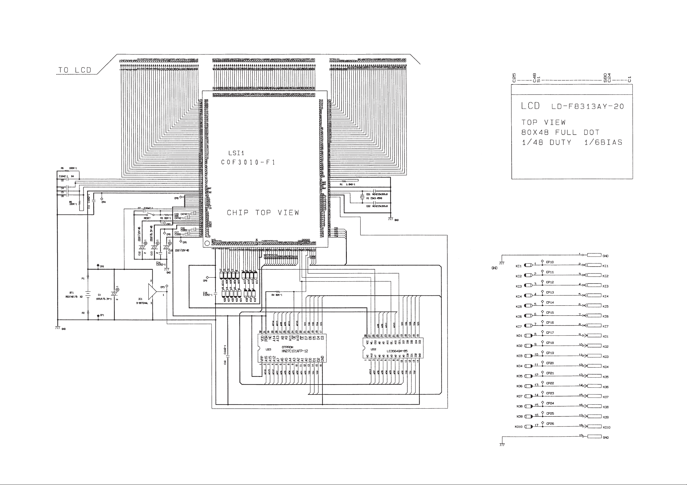
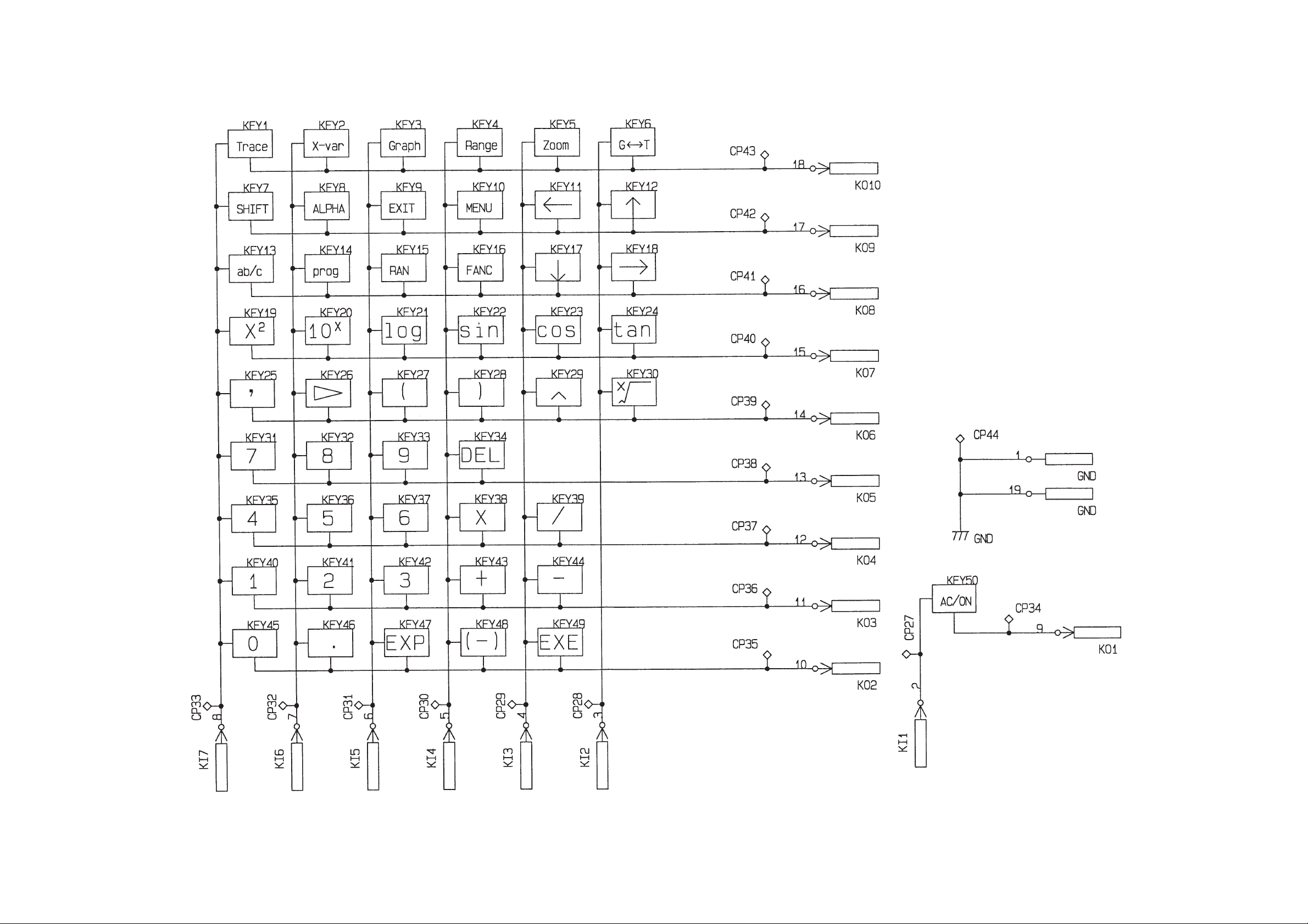
1. SCHEMATIC DIAGRAM
— 1 —
Page 4
— 2 —
Page 5

2. SPECIFICATIONS
Display system: 13-character × 6-line liquid crystal display; 10-digit mantissa and 2-
digit exponent for calculations; displays binary, octal, hexadecimal,
sexagesimal values, fraction
Power supply: Two AAA-size batteries (LR03 (AM4) or R03 (UM-4))
Power consumption: 0.05W
Battery life*: Approximately 2,000 hours (contiuuous display of initial screen) type
LR03 (AM4)
Approximately 1,000 hours (continuous display of initial screen) type R03
(UM-4)
Approximately 2 years (power switch off) with LR03 (AM4)/R03 (UM-4)
*The batteries that have been installed in this unit when user pur
chased it had been used in the factory test, so it will be impossible to
fully satisfy this specifications when these batteries are used.
Auto power off: Power is automatically switched off approximately six minutes after last
operation.
Ambient temperature range: 0°C ~ 40°C (32°F ~ 104°F)
Dimensions: 17.5mm H × 77mm W × 157.5mm D ( 3/4" H × 3" W × 61/4" D)
Weight: 120g (4.2 oz) including batteries
Accessories: Hard case
Current Consumption
TYP [µA] MAX [µA]
ON (MENU) 320 457.5
OFF 11.2
— 3 —
Page 6

3.REPLACING BATTERIES
1Switch the power of the calculator off.
2Slide the battery compartment cover on the back of the unit
RESET
in the direction indicated by the arrow.
3Remove the two old batteries.
4Load two new batteries into the calculator so that their
positive + and negative - ends are facing properly. Be
sure to replace all two batteries with new ones.
5Replace the battery compartment cover, sliding it in the
RESET
direction opposite that indicated by the arrow.
6Perform the RESET operation described below.
Important
Data stored in memory can be corrupted or lost if battery power drops below a certain level. When
this happens, you must perform the RESET operation to restore normal operation. Note that the
RESET operation clears all data from memory. Because of this, you should be sure to keep written
copies of all important data to avoid losing it due to low battery power.
4.RESET OPERATION
You should perform the RESET operation whenever you want to initialize the calculator.
Warning!
The procedure described here clears all memory contents. Never perform this operation unless you
want to totally clear the memory of the calculator.
If you need the data currently stored in memory, be sure to write it down somewhere before performing the RESET operation.
•To reset the calculator
Press
then press
MENU
to display the Main menu, and use the cursor keys to highlight the RESET icon. And
EXE
.
RESET OK?
YES
:
PRESS [EXE]
NO
:
PRESS [EXIT]
Press
EXE
to reset the calculator, or
EXE
EXIT
to abort the reset operation.
✽✽✽✽✽✽✽✽✽✽✽✽✽
MEMORY
ALL CLEARED!
✽✽✽✽✽✽✽✽✽✽✽✽✽
— 4 —
Page 7

Resetting the calculator initializes the unit to the following settings.
Item
Mode
Unit of Angular Measurement
Norm
BASE-N
Value Memories
Expanded Memory
Ans Memory
Graphic Display
Text Display
Graphic Function Memory
Program
Input Buffer
Replay Memory
Initial Setting
COMP
Deg
Norm 1
Dec
Clear
Clear
Clear
Clear
Clear
Clear
Clear
Clear
Clear
*If the calculator stops operating correctly for some reason, use a thin, pointed object to press the
RESET button on the back of the calculator. This should make the RESET confirmation screen
appear on the display. Perform the procedure described above to complete the RESET operation.
RESET button
5. ERROR MESSAGE
Message
Syn ERROR
Meaning
1 Calculation formula contains an
error.
2 Formula in a program contains an
error.
1Use or to display the point
where the error was generated and
correct it.
2Use or to display the point
where the error was generated and
then correct the program.
Countermeasure
— 5 —
Page 8

Message
Meaning
Countermeaseure
Ma ERROR
Go ERROR
Ne ERROR
Stk ERROR
1 Calculation result exceeds calcula-
tion range.
2 Calculation is performed outside the
input range of a function.
3 Illogical operation (division by zero,
etc.)
1 No corresponding Lbl n for Goto n.
2 No program stored in program area
Prog n.
•Nesting of subroutines by Prog n
exceeds 10 levels.
•Execution of calculations that exceed
the capacity of the stack for numeric
values or stack for calculations.
123
Check the input numeric value and
correct it.
When using memories, check that
the numeric values stored in memories are correct.
1Correctly input a Lbl n to correspond
to the Goto n, or delete the Goto n if
not required.
2Store a program in program area
Prog n, or delete the Prog n if not
required.
•Ensure that Prog n is not used to
return from subroutines to main
routine. If used, delete any unnecessary Prog n.
•Trace the subroutine jump destinations and ensure that no jumps are
made back to the original program
area. Ensure that returns are made
correctly.
•Simplify the formulas to keep stacks
within 10 levels for the numeric
values and 26 levels for the calculations.
•Divide the formula into two or more
parts.
Mem ERROR
Arg ERROR
1 Specified expanded value memory
does not exist.
2 Not enough memory to expand
value memories specified number.
3 Not enough memory to store statisti-
cal data.
4 Not enough memory to hold function
input in the Graph Mode for graph
drawing.
Incorrect argument specification for a
command that requires an argument.
SHIFT
1Use
Defm
to correctly expand
the number of value memories.
234
•Keep the number of value memories you use for the operation
within the number of value memories currently available.
•Simplify the data you are trying to
store to keep it within the available
memory capacity.
•Delete no longer needed data to
make room for the new data.
Correct the argument.
• Sci n, Fix n: n = integer from 0
through 9.
• Lbl n, Goto n: n = integer from 0
through 9, or alpha character from A
through Z.
• Prog n: n = 0 through 9.
• Defm n: n = integer from 0 up to the
number of remaining bytes.
— 6 —
Page 9

6. OPERATION CHECK
STEP OPERATION
Use a thin and pointed object to
1
press the RESET button on the
back of the unit.
2
3
4
5
6
7
EXE
SHIFT
Press G T AC/ON keys
at same time.
1
AC/ON
,
EXE
EXE
DISPLAY
RESET OK?
YES: PRESS
NO : PRESS
******************************
MEMORY
* *
ALL CLEARED !
* *
******************************
HARD TEST
0. RST&EXIT
1. LCD
2. RAM
3. ROM
4. KEY
All dots are displayed
Frame is displayed
EXE
EXIT
NOTE
Reset
OFF
TEST mode menu
Check for display
Check for displayNo display
Check for display
8
10
11
12
13
14
EXE
9
EXE
EXE
2
EXE
3
EXE
Checkers are displayed
Reverse checkers are displayed Check for display
HARD TEST
0. RST&EXIT
1. LCD
2. RAM
3. ROM
4. KEY
RAM Check
8K byte
OK
HARD TEST
0. RST&EXIT
1. LCD
2. RAM
3. ROM
4. KEY
ROM Check
56K byte
OK
HARD TEST
0. RST&EXIT
1. LCD
2. RAM
3. ROM
4. KEY
Check for display
TEST mode menu
RAM check
TEST mode menu
ROM check
TEST mode menu
15
4
— 7 —
Trace
Check for keys
Page 10

STEP
OPERATION DISPLAY NOTE
16
17
18
19
Trace
· · · · · ·
SHIFT (OFF) End
X-var Graph · · · · · ·
(-)
0
EXE
AC/ON
X-var, Graph, Range · · · · · ·
HAND TEST
0. RST&EXIT
1. LCD
2. RAM
3. ROM
4. KEY
******************************
*
*
******************************
MEMORY
ALL CLEARED !
*
*
Check for keys.
To push the key
sequentially that
is being appeared
in the display.
TEST mode menu
— 8 —
Page 11

7. EXPLODED VIEW
21
22
DISASSEMBLY
1. Remove the battery cover M, and loosen the six screws H on the
lower case 8, then open the lower case.
2. Loosen the six screws I on the PCB ass'y 1, and remove the PCB ass'y.
17
12
— 9 —
13
14
25
20
26
7
2
5
4
24
6
LSI1
3
1
15
16
19
8
23
18
9
11
10
Page 12

8. PARTS LIST
FOB Japan
N Item Code No. Parts Name Specification QM N.R.Yen R
Unit Price
PCB ASS'Y
N 1 6414 7040 PCB Ass'y 377XXX0300R*1 1 B
(This assembly contains the following available elements.)
IC1 2105 4074 MOS IC S-80724AL-AM-T1 110 C
N LSI1 6413 3300 COF3010-F1 sub ass'y A340137*1 1 1 C
LSI2 2011 4088 LSI LC3564QM-85 1 1 C
N C1 6414 7260 Capacitor CB1000141R6 120 C
N C2,4~7 6511 7560 Chip capacitor CP001A432T8 520 C
C11,16~18 6511 7580 Chip capacitor CP0010430T3 410 C
N C12,13 6414 7270 Capacitor CB0220241R2 220 C
C15 2803 6813 Capacitor CB0011341R3 120 C
C19,20 6511 7570 Chip capacitor CP047B632T2 210 C
C21,22 6511 7520 Chip capacitor CP030F602T7 220 C
N R1 6414 7280 Chip resistor CC0185D10E6 120 C
N R3 6414 7290 Chip resistor CC0823D10E4 120 C
R5,6 6512 1420 Chip resistor CC0015D11T0 220 C
N X1 6413 4600 Resonator BD0079P4502 1 1 C
N 2 3335 5719 LCD AC1F8313A01 1 1 C
N 3 6414 1010 Shield tape L377 A440504-1 120 C
4 6410 0830 Shield tape L180 A414656-1 120 C
N 5 6414 7240 Sponge cushion FH100031202 220 C
N 6 5610 8620 Heat seal FX22P000004 1 1 C
N 7 5610 8590 Heat seal FX20P450101 1 1 C
COMPONENTS
N 8 6414 7130 Lower case FAB03771004 1 1 C
N 9 6414 7140 Battery spring (-) EF050EG2108 120 C
N 10 6414 7150 Battery spring (+) EF040FG2113 120 C
N 11 6414 7160 Battery spring (+-) EF060EG2321 120 C
N 12 6414 7050 Upper case FAA03771008 1 1 C
N 13 6414 7060 Key top frame ass'y KG037710005 1 1 C
N 14 6414 7070 Rubber sheet (50KL) LA037710001 1 5 C
N 15 6414 7080 Rubber sheet (1KL) LA0EG210022 1 5 C
N 16 6414 7090 Reset key KB00ST20000 120 C
N 17 6414 7100 Display plate EL5G0014101 1 5 C
N 18 6405 2970 Screw MAB20010300 620 C
19 6511 7220 Screw MAB10013209 620 C
N 20 6414 8770 Key top frame (SHIFT) KC037710009 1 5 C
N 21 6414 7210 Hard case FC103771007 1 5 C
N 22 6414 7220 Rubber foot LC050015408 110 X
N 23 6414 7190 Battery cover FAD03771001 110 C
N 24 6414 7200 Lable HGG00017109 120 C
N 25 6414 8780 Key top frame (ALPHA) KC037710106 1 5 C
N 26 6414 8790 Key top frame (EXE) KC037720004 1 5 C
Notes: N– New parts R – A :Essential
M– Minimum order/supply quantity B :Stock recommended
R– Rank C :Others
Q– Quantity used per unit X :No stock recommended
— 11 —
Page 13

8-11-10, Nishi-Shinjuku
Shinjuku-ku, Tokyo 160, Japan
Telephone: 03-3347-4926
 Loading...