

Page 1

EX-S20/M20
INDEX
SEP. 2003
(without price)
EX-S20 EX-M20
R
Ver.5 : Aug. 2004
Page 2

CONTENTS
SPECIFICATIONS ....................................................................................................................................... 1
BLOCK DIAGRAM ...................................................................................................................................... 4
TEST MODE ................................................................................................................................................ 5
PROGRAM VERSION UPGRADING .......................................................................................................... 6
1. How to confirm the program version ............................................................................................. 6
2. How to update the firmware............................................................................................................ 6
3. How to restpre the firmware ........................................................................................................... 7
ADJ TOOL ................................................................................................................................................... 8
1. How to use USB ADJ Tool .............................................................................................................. 8
2. Lens Replacement ......................................................................................................................... 10
3. MAIN PCB Replacement............................................................................................................... 10
4. Current consumption .................................................................................................................... 11
VCOM DC ADJUSTMENT ........................................................................................................................ 12
THE COUNTERMEASURE FOR "SYSTEM ERROR" ............................................................................. 15
DISASSEMBLY ......................................................................................................................................... 17
EXPLODED VIEW ..................................................................................................................................... 21
PARTS LIST .............................................................................................................................................. 22
PRINTED CIRCUIT BOARDS ................................................................................................................... 23
SCHEMATIC DIAGRAMS ......................................................................................................................... 25
Page 3
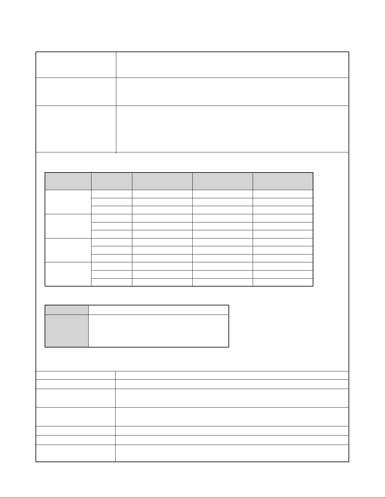
SPECIFICATIONS
Image Files Format Snapshots: JPEG (Exif Version 2.2); DCF (Design Rule for Camera File System)1.0 standard;
DPOF compliant
Movies: AVI (Motion JPEG)
Recording Media 10MB built-in flash memory
SD Memory Card
MultiMediaCard
Image Size Snapshots: 1600 x 1200 pixels
1600 x 1072 (3:2) pixels
1280 x 960 pixels
640 x 480 pixels
Movies: 320 x 240 pixels
Approximate Memory Capacity and File sizes
• Snapshots
File Size
(pixels)
1600 x 1200
(UXGA)
1600 x 1072
(3:2)
1280 x 960
(SXGA)
640 x 480
(VGA)
• Movies (320 x 240 pixels)
Data Size
Recording Time
* Based on Matsushita Electric Industrial Co., Ltd. products. Capacity depends on card manufacturer.
* To determine the number of images that can be stored on a memory card of a different capacity, multiply the capacities in
the table by the appropriate value.
Delete Single-file, all files (with protection)
Effective Pixels 2.0 million
Imaging Element 1/2.7-inch square pixel color CCD
Lens/Focal Distance F3.5/f = 5.6mm
Zoom 4X digital zoom
Focusing Fixed focus with macro mode
Focus Range Normal focus: Approximately 0.8 m to ∞ (2.6´ to ∞)
Quality
Fine
Normal
Economy
Fine
Normal
Economy
Fine
Normal
Economy
Fine
Normal
Economy
One Movie: 60 seconds maximum
Total Movie Time:
60 seconds maximum (built-in memory)
380 seconds maximum (SD 64MB memory card)*
ApproximateImage File
Size
1050 KB
710 KB
370 KB
910 KB
610 KB
300 KB
680 KB
460 KB
250 KB
190 KB
140 KB
90 KB
160KB/second max.
(Total pixels: 2.11 million)
(Equivalent to 37mm on a 35mm film camera.)
Macro focus: Approximately 30cm (11.8˝) (Optimum field of view at A4-size.)
Built-in flash memory
10MB
8 shots
12 shots
24 shots
9 shots
14 shots
27 shots
12 shots
19 shots
34 shots
46 shots
60 shots
96 shots
SD Memory Card*
64MB
57 shots
77 shots
151 shots
59 shots
89 shots
173 shots
81 shots
124 shots
217 shots
289 shots
379 shots
607 shots
— 1 —
Page 4
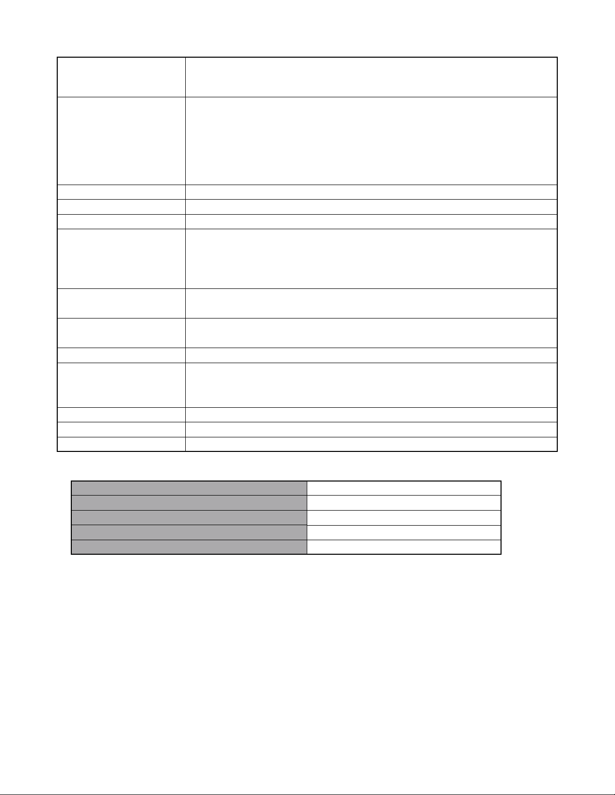
Exposure Control Metering: Multi-pattern by imaging element
Exposure: Program AE
Exposure Compensation: –2EV to +2EV (in 1/3EV steps)
Shutter CCD shutter, mechanical shutter
1/8 to 1/8000 second
(Depends on REC mode and ISO sensitivity setting being used.)
• Shutter speed is different for the following BESTSHOT scenes.
Night Scene: 1 to 1/8000 second
Fireworks: 2 seconds (fixed)
Aperture F3.5 fixed
White Balance Automatic/fixed (4 modes) /Manual
Self-timer 10 seconds, 2 seconds, Triple Self-timer
Built-in Flash Flash Modes: Auto, Off, On, Red-eye reduction
Approximate Flash Range
Recording Functions Snapshot ; Macro; self-timer; BESTSHOT; Movie ; voice recording
* Audio is monaural
Monitor Screen 1.6-inch TFT color LCD
84,960 pixels (354 x 240)
Viewfinder Monitor screen and optical viewfinder
Timekeeping Functions Built-in digital quartz clock
Date and Time: Recorded with image data
Auto Calendar: To 2049
World Time City; Date; Time; Summer time; 162 cities in 32 time zones
Input/Output Terminals Cradle connector
Power Requirements Rechargeable lithium ion battery (NP-20) x 1
Approximate Battery Life:
The above values indicate the amount of time under the conditions defined below, until power automatically turns off due to
Number of Shots,Continuous Recording*1 (Recording Time)
Number of Shots,Normal Recording*2 (Recording Time)
Continuous Playback*3 (Continuous Snapshot Recording)
Continuous Voice Recording*4
Continuous Audio Playback*5
: Wide Angle Optical Zoom: 0.4 to 2.9 meters (1.3´ to 9.5´)
Telephoto Optical Zoom: 0.4 to 1.7 meters (1.3´ to 5.6´)
(ISO Sensitivity: “Auto”)
720 shots (120 minutes)
190 shots (95 minutes)
180 minutes
170 minutes
450 minutes
battery failure. They do not guarantee that you will be able to achieve this level of operation. Low temperatures shorten battery
life.
*1 Continuous Recording Conditions
• Temperature: 23°C (73°F)
• Monitor screen: On
• Flash: Off
• Image recorded about every 10 seconds
*2 Normal Recording Conditions
• Temperature: 23°C (73°F)
• Monitor screen: On
• Flash: On (one flash every two shots)
• Image recorded about every 30 seconds
• Power off/on every 10 shots
*3 Continuous Playback Conditions
— 2 —
Page 5

• Temperature: 23°C (73°F)
• Scroll one image about every 10 seconds
*4 Voice recording times are based on continuous recording.
*5 Audio playback times are based on continuous output (through headphones).
Power Consumption DC 3.7V Approximately 2.5W
Dimensions 83(W) x 53(H) x 11.3(D) mm (3.3˝(W) x 2.1˝(H) x 0.44˝(D))
(excluding projections)
Weight Approximately 78 g (2.8 oz)
(excluding battery and accessories)
Bundled Accessories Rechargeable lithium ion battery (NP-20); USB Cradle (CA-23); Special AC Adaptor (AD-C51G);
AC power cord; Strap; USB cable; CD-ROM; Basic Reference
Rechargeable Lithium Ion Rated Voltage: 3.7 V
Battery (NP-20) Rated Capacitance: 680 mAh
Operating Temperature
Range: 0°C to 40°C (32°F to 104°F)
Dimensions: 33 (W) x 50 (H) x 4.7 (D) mm (1.3˝ (W) x 2.0˝ (H) x 0.19˝ (D))
Weight: Approximately 16 g (0.56 oz)
Special battery charger Power Requirement 100 to 240V AC, 0.08A, 50/60Hz
unit (BC-5H) : Inlet Type Output DC 1.2V, 550mA
Charging Temperature 0°C to 40°C (32°F to 104°F)
Chargeable Battery type
Full Charge Times Approximately 4 hours
Dimensions 71 (W) x 75 (H) x 28 (D) mm (2.8˝ (W) x 30˝ (H) x 1.1˝ (D))
Weight Approximately 75 g (2.6 oz)
Special AC Adaptor Power Requirement 100 to 240V AC, 50/60Hz, 83mA
(AD-C51G) Output 5.3V DC, 650mA
Dimensions 78(W) x 20(H) x 39(D) mm (3.1˝(W) x 0.78˝(H) x 1.5˝(D))
Weight Approximately 90 g (3.2 oz)
Rechargeable nickel-metal hydride batteries (HR-3UA)
(excluding projections)
(excluding projections and cable)
Power Supply
• Use only the special NP-20 rechargeable lithium ion battery to power this camera. Use of any other type of battery is not
supported.
• This camera does not require a battery for the clock. The date and time settings of the camera are cleared whenever power
supplied by both the battery and USB cradle is interrupted. Be sure to reconfigure these settings after power is interrupted (page
39).
LCD Panel
• The LCD panel is a product of the latest LCD manufacturing technology that provides a pixel yield of 99.99%. This means that
less than 0.01% of the total pixels are defective (they do not turn on or always remain turned on).
Lens
• You may sometimes notice some distortion in certain types of images, such as a slight bend in lines that should be straight. This
is due to the characteristics of lens, and does not indicate malfunction of the camera.
— 3 —
Page 6
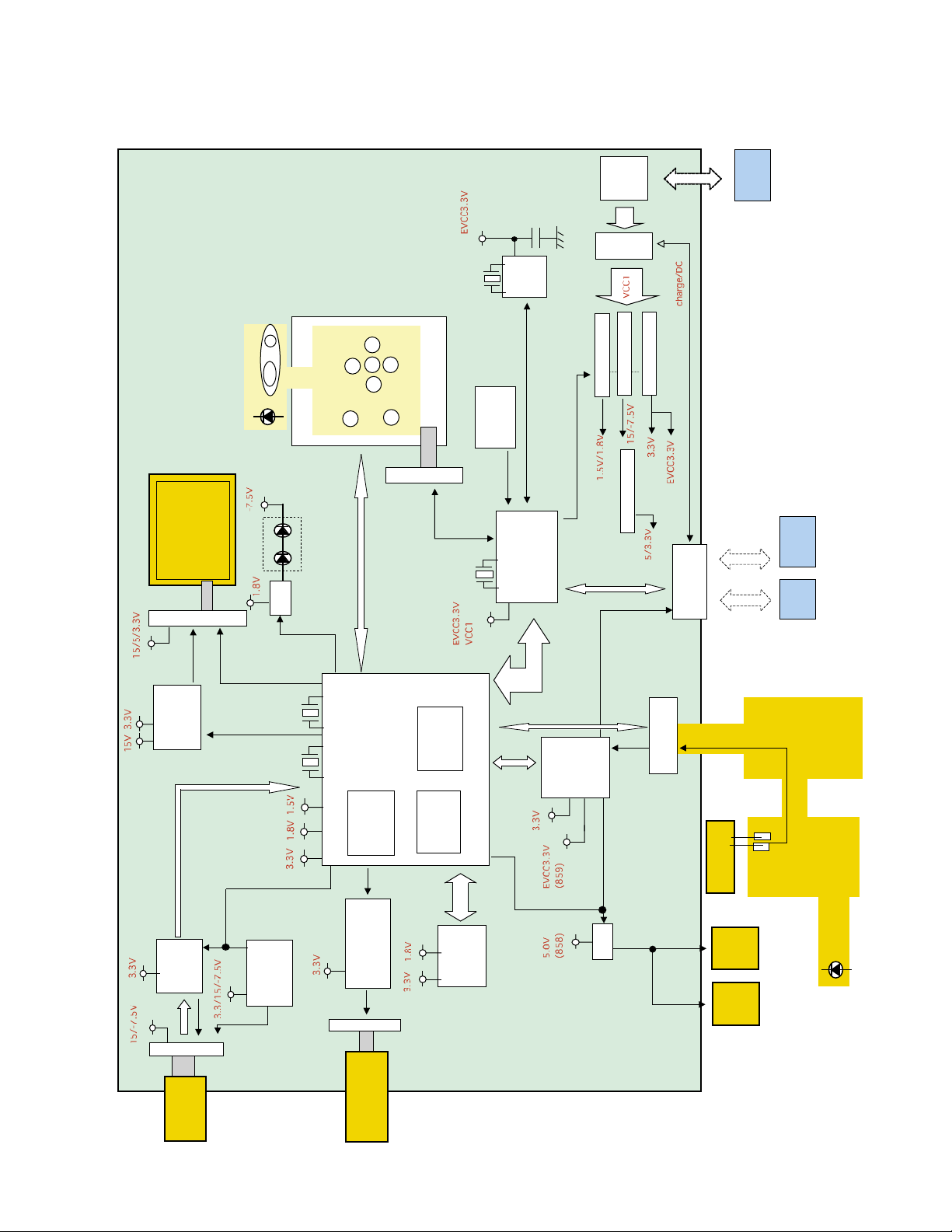
Main-PCB
1.6 inch TFT
CN500(33pin)
LED SHUT PW
SD Connecter
Q506
Back light
BLOCK DIAGRAM
SW unit
CN800(7pin)
key,LED
SD-bus
32kHz
10MHz
back up
RTC
ACRO SW
REC/PLAY/M
key
8bit micom
capacitor
R2051
IC200
Down converter
PWCTL0,1,3
8MCU-bus
spring
Battery
Fuse
1.6A
U/D converter
Down converter
Down converter
Connecter
26pin Credle
Li-ion
Battery
Credle Remocon
,504
VCOM
Q500,502
10bit-DATA
IC300
CDS/AD
module
2M CCD-Lenz
VCOM
CCD-bus
CN508(18pin)
LCD-bus
V-Driver
48MHz 27MHz
IC302
Micom
Shutter driver
Q508,510,512.514
CN502(4pin)
Lenz barrier/
IRF LPF unit
Mechanical shutter/
ASIC
IC500 ( MCP )
SDRAM
16M NAND
Flash Memory
audio bus
8bit-MPU
bus
ADC/Sound
HeadPhone
Amp
IC706(859)
Q700
strobe bus
CN504(13pin)
Microphone
SP
(859)
(858)
Buzzer
Strobe Unit
Self Timer LED
— 4 —
Page 7
TEST MODE
Note: Do not perform the menu item unless explained here. (It may damage the internal data and
camera becomes unusable.)
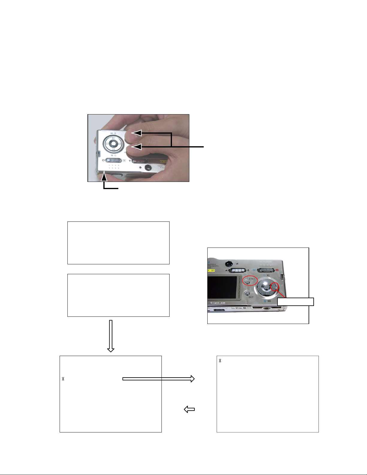
Booting
To boot the test mode
While firmly pressing down both "MENU" and "DISP" buttons, Turn the power on.
1 "MENU" + "DISP" button
2 "POWER" button
■ EX-S20
++ KX858 ++
PR : 03.09.08.13.22
LD : 1.45
MI : 17
■ EX-M20
++ KX859 ++
PR : 03.09.08.13.25
LD : 1.45
MI : 17
"Right" button -> "Right" button "MENU" button
1 :VERSION INFO
2 :VIDEO OUT
3 :USB TCC TEST
4 :TEST MENU
5 :SOUND TEST
6 :BAYER MODE
7 :ROM UPDATE
8 :ADJ TEST
9 :REC-INFO
10 :TEST SCRIPT
11 :LAST MEMORY
12 :FORMAT
"SET" button
"MENU" button
"Right" button
1 :KEY CHECK
2 :MEMORY CHECK
3 :COLOR CHECK
4 :MESSAGE CHECK
5 :LED CHECK
6 :SW&JACK CHECK
7 :MIC CHECK
8 :BEND1 MASK
— 5 —
Page 8

PROGRAM VERSION UPGRADING
■ Introduction
Update the program using an SD card.
Note:
Make sure to use a fully charged battery.
MAIN PCB becomes unusable if power down or an error occurs during program transmission.
1. How to confirm the program version
■ The program version can be confirmed in the test menu (refer to the previous page).
■ Turn the power on while pressing MENU button.
The following program version can be found.
Check the LCD display.
(Example)
VER 1.00
(As of September 10. 2003)
2. How to update the firmware
1. Prepare the memory card which contains the software for upgrading EX-S20/M20 firmware in the root
directory.
firmware: EX-S20................. ex-s20.bin
EX-M20 ................ ex-m20.bin
The firmware is included in the service CD-ROM.
The location is as follows: QV/Soft/Adj-soft/EXs20_m20/FirmUP
2. Insert the above memory card in the camera and then set a fully charged battery in the camera.
3. While pressing MENU, press power switch. Keep pressing MENU until “PROGRAM UPDATE” appears
in the camera LCD.
• The following appears.
• The version for the firmware update software in the memory card appears at the bottom.
PROGRAM UPDATE
YES
NO
NEW VERSION IS
VER 1.00
Note:
This does not appear when the battery is low.
Make sure to charge the battery fully.
4. Align the white cursor to “YES” by the cross key of 왖 and 왔, and press SET of the center of the cross
key.
• “NOW LOADING” appears in the LCD and the update starts.
5. “COMPLETE” appears after the update finishes.
— 6 —
Page 9

6. Remove the memory card after turning the power off once. Turn the power back on again while pressing
MENU, and check the version.
VER 1.00
(As of September. 2003)
7. If the version is correct, turn the power off.
8. Finally, check the operation by recording, playing back and deleting an image.
3. How to restore the firmware
1. Prepare the following firmware restoration program and change its name as follows;
EX-S20: rom858_030908.lbn 앶앸 jupiter.bin
EX-M20: rom859_030908.lbn 앶앸 jupiter.bin
The program is included in the service CD-ROM.
Location: QV/Soft/Adj-soft/EXs20_m20/Recover
2. Copy the above file to the root directory in the memory card.
3. Insert the memory card into the camera.
4. Set a fully charged battery in the camera.
5. Turn the power on while pressing the shutter release button.
The LED next to the optical finder changes from green/red blinks 앶앸 green blinks 앶앸 green lights.
6. When the green LED lights, the firmware restoration is finished.
Remove the battery.
7. Turn the power on again while pressing MENU and DISP buttons.
The firmware is successfully restored if the following version appears.
EX-S20: PR: 03.09.08.13.22
EX-M20: PR: 03.09.08.13.25
8. Finally, start the camera normally to check the operation by recording, playing back and deleting an
image.
— 7 —
Page 10

ADJ TOOL
■ Introduction
Make sure to perform the adjustment when replacing the lens unit or the MAIN PCB.
The necessary software, driver and setting are explained in using USB ADJ Tool "adj03natsu.exe".
Note that the tool, drivers etc. are available only for Windows.
1. How to use USB ADJ Tool
1-1. Prepare the necessary software, driver and DLL file.
(1) Prepare the following three files.
• Commom test driver for CASIO/PENTAX
[testmode_pentax_casio] folder uusbd.dll
uusbd.inf
uusbd.sys
• ADJ data read/write tool "adj03natsu.exe"
• Commom DLL for USB test "uusbd.dll"
(2) Place the commom test driver for CASIO/PENTAX in an appropriate place.
(3) After downloading the common DLL for USB test, copy it to the same directory as that of the ADJ data
read/write tool or under "c:windows/system.
1-2. Set the camera so that it recognizes the USB test mode.
(1) Enter the test mode and then the initial test selection screen.
Turn the power on while pressing both "MENU" and "DISP".
Press "RIGHT", "RIGHT" and "MENU.
(2) Move the cursor to "3:USB TCC TEST" and press "SET".
(3) Move the cursor to "1:USB TCC ON" and press "SET".
(4) Press "MENU" button and leave the test mode.
(5) This enables the camera to recognise the USB test mode flag.
(6) When the USB test mode flag is ON, the test menu appears first when the camera power is turned on.
* If the USB test mode flag should be OFF, set "2: USB TCC OFF" in the test menu.
1-3. Install the USB driver for the USB test mode in the computer.
(The following is an example using the Windows Me.)
(1) Prepare the USB driver for the USB test mode.
(2) Turn the camera power on which is set in the USB test mode and let it enter the USB test mode as
shown in 1-2.(the test menu appears right after the power is turned on).
(3) Connect the camera in the above status to the computer by the USB cable.
(4) "A wizard for the new hardware" appears.
(5) Check "Designate the place for the driver (for users with sufficient knowledge)" and press "Next".
(6) Check "Search for the optimum driver for the device (recommended)".
(7) Check "Designate the place to search" , designate the place which contains "inf" file in the driver by
pressing "Reference" button, and then press "Next" button.
(8) When "Universal USB Driver (VMEM manufacturer's name)" appears upon message "Searching for
the driver file for the following devices" , press "Next" button.
(9) The file copy starts.
(If a message "uusbd.Inf cannot be found" appears during the file copy, designate the same place as in
the step 7).
(10) Press "Complete" button.
(11) Right-click "My computer", select "Property" and open "Device manager". If "Universal USB Driver
(VMEM manufacturer's name)" can be found in "USB device for UUSBD", the computer has successfully
recognised the driver.
(12) The test driver can be used for both CASIO/PENTAX. Installing the test driver into either one enables
the other one to recognise it.
— 8 —
Page 11

NOTE: How to uninstall the USB driver for the USB test mode
• Connect the camera while in the USB test mode to the computer so that the computer recognises the
camera.
• Right-click "My computer", select "Property" and open "Device manager".
• Select "USB device for UUSBD" , and then "Universal USB Driver (VMEM manufacturer's name)".
• Press "Delete" button and delete the driver.
• When using Windows98/98SE/Me, delete the following three files;
(NOTE! Do NOT delete "usbd. inf" and "usbd.sys", whose names are much alike the following.)
C:windows / inf / uusbd.inf
C:windows / inf / other / KashiwanoUUSBD.inf
C:windows / system32 / drivers / uusbd.sys
• The driver has been successfully deleted.
1-4. Use the USB ADJ Tool
(1) Prepare ADJ data read/write tool "adj03natsu.exe".
(2) Copy the common DLL for USB test to the same directory as that of the ADJ data read/write tool
"adj03natsu.exe" or under "c:windows / system".
(3) Turn the camera power on which is set in the USB test mode and let it enter the USB test mode (the test
menu appears right after the power is turned on).
Connect the camera to the computer by the USB cable.
(4) Boot "adj03natsu.exe" and use it as follows;
• Read ADJ data from the camera. Press "read from the camera".
• Write ADJ data into the camera. Press "write into the camera".
• Save ADJ data which is read. Press "File" and "Save", and save it with an appropriate name.
• Open ADJ data which is saved. Press "File" and "Open", and open the necessary file.
— 9 —
Page 12

2. Lens Replacement
Make sure to perform the following procedure after replacing the lens.
A floppy disk with the lens data is bundled in the spare parts of the lens unit.
1 Enter the TEST mode.
1.Turn the power on while pressing both "MENU" and "DISP" buttons.
2.Press "RIGHT" button, "RIGHT" button and "MENU" button while
the program version is displayed.
3.Select "3.USB TCC TEST", and press "SET" button.
4.Select "1. USB TCC ON", and press "SET" button.
5.Turn the power OFF.
2 Set the camera to the cradle and turn the power on and connect it to the
computer by the USB cable.
3 Boot "adj03natsu.exe" .
4 Click "ADJ ALL READ", and display the data on the "adj03natsu.exe".
5 Find the No.473, "V-COM DC".
6 Write down this value(data).
7 Replace the Lens unit.
8 Perform the above 1 to 3
9 From "File/Open", open the bundled floppy disk, and transfer the data to
the "adj03natsu.exe".
0 Find the No.473,"V-COM DC"
A Change the data to the former value.(Refer to 6).
B Click "WRITE" button of "ADJ ALL".
C After adjustment, change "1. USB TCC ON" to "2. USB TCC OFF".
5
9
3. MAIN PCB Replacement
Make sure to backup ADJ DATA before replacing the MAIN PCB.
Firmware is not installed in spare parts.
1 Enter the TEST mode.
1. Turn the power on while pressing both "MENU" and "DISP" buttons.
2. Press "RIGHT" button, "RIGHT" button and "MENU" button while the program version is displayed.
3. Select "3.USB TCC TEST", and press "SET" button.
4. Select "1. USB TCC ON", and press "SET" button.
5. Turn the power OFF.
2 Set the camera to the cradle and turn the power on and connect it to the PC by the USB cable.
3 Boot "adj03natsu.exe" .
— 10 —
B
Page 13

4 Click "ADJ ALL READ", and display the data on the "adj03natsu.exe".
5 Save the data.
6 Replace the MAIN PCB.
7 Writing the Firmware
Write the firmware into a spare part after replacing one.
NOTE: If a battery is inserted without the firmware, only LED blinks
green and the camera does not operate.
1. Write the firmware
a)
Copy the following restoration software and the firmware to a SD card.
Restoration software: EX-S20 ......rom858_030908.lbn
EX-M20......rom859_030908.lbn
Firmware: EX-S20 ......ex-s20.bin
EX-M20 ex-m20.bin
b) Copy both the restoration software and the firmware into the root
directory of the SD card.
c) Change the name of the restoration software to "jupiter.bin".
d) Insert the SD card.
e) While pressing the shutter key, insert a fully charged battery.
f)
The LED changes from "green/red blink" "green blinks" "green lights".
g) After the LED lights green, the firmware is written.
h) Remove the battery.
2. Initialize the system
a) Enter the TEST mode.
b) Select "7:ROM UPDATE" and press SET button.
c) Next, select "5:SYSTEM INITIAL" and press SET button.
d) The following message appears.
SYSTEM INITIALIZE
START
...
PUSH OK KEY?
e) Press SET button and System is initialized.
But the message, "SYSTEM ERROR", still appears on the monitor.
3. Write firmware again
Refer to the "How to update the firmware" on page 6.
Write the firmware.
If the TEST mode boots automatically, change "USB TCC ON" to
"USB TCC OFF".
8 Perform the above 1 to 3.
9 Open the file which is saved above, and display the data on the
"adj03natsu.exe".
0 Click "WRITE" button of "ADJ ALL".
A After adjustment, change "1. USB TCC ON" to "2. USB TCC OFF".
5
4
9
4. Current consumption
(1) Current consumption (DC in = 3.70 ~ 4.05 [V])
• Make sure that current consumption is less than 260 mA in PLAY mode.
• Make sure that current consumption is less than 390 mA in REC mode.
• Make sure that current consumption is 0.8 ~ 2.0mA when power is turned OFF.
(less than 500 µA after the backup capacitor was charged.)
(2) The battery indicator changes according to the voltages as follows.
• DC in = less than 3.74 ± 0.02V: (PLAY mode)
• DC in = less than 3.67 ± 0.02V: (PLAY mode)
• DC in = less than 3.51 ± 0.02V: (PLAY mode)
— 11 —
0
Page 14

VCOM DC ADJUSTMENT
■ Purpose
Readjust the VCOM value to minimize the flicker of the LCD after replacing the LCD or the main PCB.
■ Necessary tools
1. Camera (Charge its battery fully)
2. Photo diode (S2281-01) : See Fig 1.
3. Photo sensor amp (C2719) : See Fig 2.
4. BNC-BNC cable (E2573) x 2 : See Fig 3.
5. 9-volt alkaline battery (6LR61Y) x 2 : See Fig 4.
6. Oscilloscope
■ Preparation
1. The three tools can be obtained from the following global site.
Photo diode (S2281-01)
Photo sensor amp (C2719)
BNC-BNC cable (E2573)
www.hamamatsu.com/
2. 9-volt alkaline battery is a standard one, but can be obtained from the following global site as well.
www.panasonic.co.jp/global/
Fig1 Photo Diode (S2281-01) Fig2 Photo Sensor Amp (C2719)
Fig3 BNC-BNC Cable (E2573) Fig4 6LR61Y
— 12 —
Page 15

■ Procedure
1. Camera setting
a) Turn the power on while pressing MENU and DISP.
After pressing “Right” key twice, press MENU.
Figure (a) appears.
b) Select “8 : ADJ_TEST” and then press SET.
(See Figure (b).)
c) Next, select “1. VCOM” and then press SET.
(See Figure (c).)
Figure (a)
1 :VERSION INFO
2 :VIDEO OUT
3 :USB TCC TEST
4 :TEST MENU
5 :BEEP TEST
6 :TASK-2 TEST
7 :ROM UPDATE
8 :ADJ TEST
9 :REC-INFO
10 :TEST SCRIPT
11 :LAST MEMOR
Figure (b)
1:VCOM 7f
2:SHUT
3:AWB
.
.
.
Figure (c)
VCOM ADJ START?
<<START>>
PUSH OK KEY?
<<STOP>>
PUSH PW KEY?
Y
Figure (d)
d) Pressing SET causes the right figure to appear.
(See Figure (d).)
This value is an example and differs by products.
OK -> Register Write
VCOM = 0x7f
2. Connecting the TOOL
a) Place two 9-volt alkaline batteries in C2719.
b)
Connect the output terminal of C2719 to the channel terminal of the oscilloscope by the BNC-BNC cable.
c) Connect the input terminal to the Photo Diode by the BNC cable.
d) Turn the oscilloscope and C2719 on.
* Pull the ON/OFF switch of C2719 this way and raise/lower it. (See below Figure.)
— 13 —
Page 16

3. Measurement
a) Connect S2281-01 to the camera’s LCD monitor (see below).
AC Waveforms appear on the monitor screen of the oscilloscope.
* Change the Rf range of C2719 in case the range does not match.
Photo diode
S2281-01
INPUT OUTPUT
Oscilloscope
Photo sensor amp
CAMERA
BNC-BNC cable
LCD
Minimize the
ripple components
b) After AC waveforms of the oscilloscope appear , minimize it by pressing the camera’s up/down buttons
(see the picture).
Make sure to visually check if it has been minimized.
"Up" button
After it has been minimized, press SET key.
The screen in the right figure appears and the new VCOM
is written (VCOM adjustment is finished.).
This value is only an example, and differs by products.
Return to the previous display by pressing MENU or PW key.
"Down" button
OK -> Register Write
VCOM = 0X80
LAST MEMORY SET!
— 14 —
Page 17

THE COUNTERMEASURE FOR "SYSTEM ERROR"
■ Purpose
System error may occur when the battery is removed while data is written to the internal memory.
If "SYSTEM ERROR" appears on the monitor, execute the following operation.
1. Back up the ADJ DATA.
2. Initialize the system.
3. Write the firmware.
4. Initialize the system again in order to initialize ADJ DATA.
5. Write the firmware again.
6. Return the backed up ADJ DATA.
7. Check the operation in the test mode.
■ PROCEDURE
1. Back up the ADJ DATA(Refer to the page 10 to 11).
a) Enter the TEST mode.
Turn the power on while pressing both "MENU"and "DISP" buttons.
Press "RIGHT" button, "RIGHT" button and "MENU" button.
b) Select "3.USB TCC TEST", and press "SET" button.
c) Select "1.USB TCC ON", and press "SET" button.
d) Turn the power OFF.
e) Set the camera to the cradle and turn the power on and connect it to the PC by the USB cable.
f )Boot "adj03natsu.exe".
g) Click "ADJ ALL READ", and display the data on the "adj03natsu.exe".
h) Save the ADJ data.
Proceed to the next operation even if ADJ DATA cannot be saved.
2. Initialize the system.
a) Enter the TEST mode.
b) Select "7:ROM UPDATE" and press SET button.
c) Next, select "5:SYSTEM INITIAL" and press SET button.
d) The following message appears.
SYSTEM INITIALIZE
START
PUSH OK KEY?
e) Press SET button and System is initialized.
But the message, "SYSTEM ERROR", still appears on the monitor.
3. Write firmware.
Refer to the "How to update the firmware" on page 6.
Write the firmware.
If the TEST mode boots automatically, change "USB TCC ON" to "USB TCC OFF".
4. Initialize the system again.
Operation is the same as 2.
Proceed to the next operation even if "SYSTEM ERROR" appears on the monitor.
5. Write the firmware again.
Operation is the same as 3.
...
— 15 —
Page 18

6. Return the backed up ADJ DATA.
a) Select "USB TCC ON".
b) Set the camera to the cradle and turn the power on and connect it to the PC by the USB cable.
c) Boot "adj855.exe".
d) Open the file which is saved above and display the data on the "adj03natsu.exe".
e) Click "WRITE" button of "ADJ ALL".
7. Operation check
Boot TEST MODE.
Select "8:ADJ TEST" and press SET button.
a) When ADJ DATA can be backed up;
If both "3:AWB" and "6:KIZU" are OK, adjustment is completed.
In case "3:AWB" or "6:KIZU" is not OK, repeat the operation 2 and 3.
b) When ADJ DATA can not be backed up;
"AWB" and "KIZU" are "????".
Check the images in the REC mode and Play mode.
Adjustment is completed if the camera works properly.
After check, boot TEST mode again.
Select "3.USB TCC TEST", and press "SET" button.
Select "2.USB TCC OFF", and press "SET" button.
Replace the Main PCB if the camera does not recover.
— 16 —
Page 19

1. Remove the battery.
2. Remove the five screws.
DISASSEMBLY (EX-M20)
3. Separate the rear case.
screw
screws
— 17 —
screws
Page 20

4. Lift the LCD UNIT once, disconnect the two CONNECTORs and then remove the LCD UNIT.
connectors
5. Remove the connector and the hooks, and then remove the power unit and the key unit.
connector
hooks
6. Disconnect the four CONNECTORs and remove the MAIN PCB.
Using tweezers enables an easier removal of the PCB as shown in the figure.
When assembling, make sure that the lead wire does not get pinched
by the case.
— 18 —
Page 21

7. Discharge the strobe condenser.
8. Remove the LENS UNIT.
hooks
9. Remove the BS unit.
10. Remove the speaker unit.
— 19 —
Page 22

11. Remove the strobe unit.
hook
hook
12. Remove the finder unit.
Using tweezers enables an easier removal of the finder as shown in the figure.
— 20 —
Page 23

EXPLODED VIEW
3
5
7
8
Battery
20
1
13
12
S1
19
11
2
4
6
9
10
14
S1
15
16
18
S1
— 21 —
17
Page 24

PARTS LIST
QTY
N SpecificationParts NameParts CodeItem
N 1 1013 3557 PCB ASSY RJK505006*001 TK 1 1 1 0 DU A
N 1 1013 6888 PCB ASSY RJK505006*002 TK 0 0 0 1 DY A
N 2 1013 3553 ASSY/FRONT CASE RJK504947*001 TK 1 0 0 0 CV B
N 2 1013 3554 ASSY/FRONT CASE RJK504947*003 TK 0 1 0 0 CX B
N 2 1013 3555 ASSY/FRONT CASE RJK504947*004 TK 0 0 1 0 CX B
N 2 1013 3549 ASSY/FRONT CASE RJK504947*002 TK 0 0 0 1 CX B
N 3 1013 6214 BUZZER 7BB-12-9A15 1 1 1 0 AF C
N 4 1013 2195 SPEAKER SCB-13F 0 0 0 1 AP C
N 5 1013 2196 MIC ELM6253-0201G 0 0 0 1 AM C
N 6 1013 2192 HOLDER/SPEAKER RJK504997-001V01 0 0 0 1 AC C
N 7 1013 2185 STROBE UNIT XEST-K858 1 1 1 1 CE C
N 8 1013 2187 FINDER AQJ-1411 1 1 1 1 BC C
N 9 1013 3558 LENS UNIT RJK505003*001 TK 1 1 1 1 DU A *1
N 10 1013 2188 BS UNIT AQV-1410 1 1 1 1 CD C
N 11 1013 2201 HOLDER/GRIP RJK504957-001V01 1 1 1 1 AI C
N 12 1013 2203 TAPE/GRIP RJK504959-001V01 1 1 1 1 AA C
N 13 1013 2202 GRIP RJK504958-001V01 1 1 1 1 AT C
N 14 1013 3550 ASSY/REAR CASE RJK505035*001 TK 1 0 0 0 CT B
N 14 1013 3551 ASSY/REAR CASE RJK505035*003 TK 0 1 0 0 CX B
N 14 1013 3552 ASSY/REAR CASE RJK505035*004 TK 0 0 1 0 CX B
N 14 1013 3548 ASSY/REAR CASE RJK505035*002 TK 0 0 0 1 CT B
- 15 1011 3024 SEAL RJK504361-001V01 1 1 1 1 AA C *2
N 16 1013 3559 ASSY /BATTERY COVER RJK504966*001 TK 1 0 0 1 AQ C
N 16 1013 3560 ASSY /BATTERY COVER RJK504966*002 TK 0 1 0 0 AW C
N 16 1013 3561 ASSY /BATTERY COVER RJK504966*003 TK 0 0 1 0 AW C
N 17 1013 3556 DISPLAY ASSY RJK504982*001 TK 1 1 1 1 DE B
N 18 1013 2184 SW UNIT UBF014E01A 1 1 1 1 BQ C
- 19 1011 3514 PLATE/RATING RJK504533-002V01 1 0 0 1 AA C
N 19 1013 2973 PLATE/RATING RJK505324-003V01 0 1 0 0 AA C
N 19 1013 2974 PLATE/RATING RJK505324-004V01 0 0 1 0 AA C
N201013 2181FRAME/BATTERYRJK504994-001V01 1
- S1 1008 1372 SCREW RJK502836-001V01 5 5 5 5 AA C
EX-S20 RemarksR
Silver Red Yellow
1 1 1 AC
EX-M20 Code
Price
C
ACCESSORY
N - 1013 4894 CD-ROM CK858DBA01R 1 1 1 1 AG C For USA only
N - 1013 4895 CD-ROM CK858DCA01R 1 1 1 1 AG C Except USA
- - 1000 6299 AC CORD CBL-K799-AC-JU 1 1 1 1 AO C Blade type
- - 1009 0406 AC CORD CBL-K851-AC-UK 1 1 1 1 BE C UK type
- - 1000 6300 AC CORD CBL-K799-AC-EU 1 1 1 1 AR C Euro type
- - 1011 3059 BATTERY/LITHIUM ION MK11-2501 1 1 1 1 BW B
N - 1013 4892 AC-ADAPTOR AD-C51G-WW 1 1 1 1 BH C *3
N - 1013 4890 AC-ADAPTOR AD-C51J-WW 1 1 1 1 BH C *4
N - 1013 4889 CRADLE R68-8183 1 1 1 1 CI B
- - 1008 5898 USB CABLE UC-K851-CL10 1 1 1 1 AO C
N - 1013 4888 STRAP ST-K858-Y 1 1 1 1 AC C
- - 1008 5911 HEADPHONE HP-K852-SR 0 0 0 1 AW C
- - 1008 5912 REMOTE CONTROLLER R66-5819 0 0 0 1 CO C
N: New parts
R: Rank
*1: Floppy disk is attached in the spare parts.
*2: The seal turns red when it gets wet.
*3: AC cord is not built-in.
*4: Blade type AC cord is built-in.
— 22 —
Page 25

PRINTED CIRCUIT BOARDS
TOP VIEW
— 23 —
Page 26

BOTTOM VIEW
— 24 —
Page 27

EX-S20 PCB (1/3)
SCHEMATIC DIAGRAMS
— 25 —
Page 28

EX-S20 PCB (2/3)
— 26 —
Page 29

EX-S20 PCB (3/3)
— 27 —
Page 30

EX-M20 PCB (1/3)
— 28 —
Page 31

EX-M20 PCB (2/3)
— 29 —
Page 32

EX-M20 PCB (3/3)
— 30 —
Page 33

Ver.1 :
Replacement of the PARTS LIST (P23)
Ver.2 : Nov. 2003
Deletion of "HOW TO DELETE THE MOVIE FUNCTION"
Replacement of the PARTS LIST (P22)
Ver.3 : Dec. 2003
Replacement of the PARTS LIST (P22)
Ver.4 : May. 2004
Replacement of the EXPLODED VIEW (P21)
Ver.5 : Aug. 2004
Replacement of the EXPLODED VIEW (P21)
Replacement of the PARTS LIST (P22)
CASIO TECHNO CO.,LTD.
Overseas Service Division
6-2, Hon-machi 1-Chome
Shibuya-ku, Tokyo 151-8543, Japan
 Loading...