

Page 1
SERVICE MANUAL
& PARTS LIST
REF. NO. S/M-558
JUNE 1997
MODULE NO.
QW-1664
DW-9100BJ
Ver.1 : Jun. 2005
R
(WITHOUT PRICE)
Page 2

CONTENTS
1. SPECIFICATIONS: QW-1664........................................................................ 1
2. OPERATION CHART: QW-1664................................................................... 2
3. DRAWINGS
3-1. BLOCK DIAGRAMS: QW-1664 ........................................................................ 9
3-2. CHECKING TERMINALS AND COMPONENTS: QW-1664 .......................... 10
3-3. A1 ~ A4 PADS................................................................................................. 10
4. EXPLODED VIEW: QW-1664...................................................................... 11
5. PARTS LIST: QW-1664............................................................................... 12
6. PRECAUTIONS FOR REPAIR: QW-1664
6-1. AC (ALL CLEAR) AND REMOVING OF MODULE ........................................ 13
6-2. ACCURACY CHECKING ................................................................................ 13
1. SPECIFICATIONS: QW-1664
Item Detail
Battery CR2016
Battery life Approx. 1.5 years
Current consumption 2.78 µA maximum
Alarm system Piezo plate on Cover/Back
Accuracy ±15 sec./month
Accuracy setting system Capacitor/Chip
Accuracy checking See page 13
Accuracy setting +0.25 ~ +0.35 sec./day
Functions • Electro-luminescent backlight
• Auto light switch
• Low-temperature resistance (–20 °C)
• Altimeter
Measuring range: 0 m to 6,000 m
Measuring unit: 5 m
Auto/Manual memory measurements (up to 50 sets of data, each set
including altitude, temperature, month, data, time)
Reference altitude setting
Altitude alarm
Altitude tendency graph
• Barometer
Display range: 460 hPa/mb to 1,100 hPa/mb
Display unit: 1 hPa/mb
Tendency graph of atmospheric pressure
• Thermometer
Display range: –20 °C to 60 °C
Display unit: 0.1 °C
• 1/100 sec. stopwatch
Measuring capacity: 23:59'59.99"
Measuring mode: Elapsed time, split time, 1st-2nd place times
• Daily alarm
• Hourly time signals
• Regular time keeping: Hr, min, sec, am/pm, year, month, date, day
• Auto-calendar (pre-programmed to the year 2039)
• 12/24-hour formats
— 1 —
Page 3
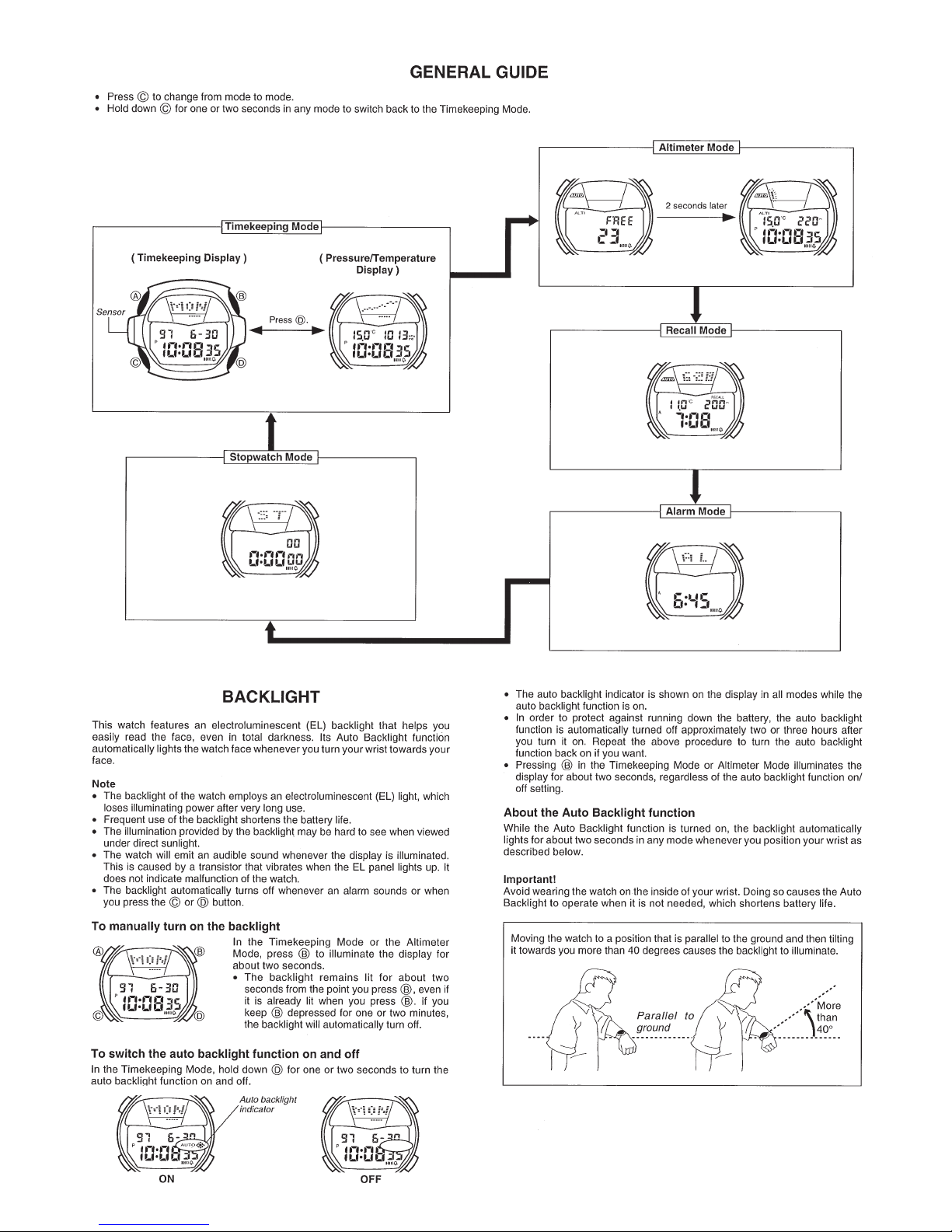
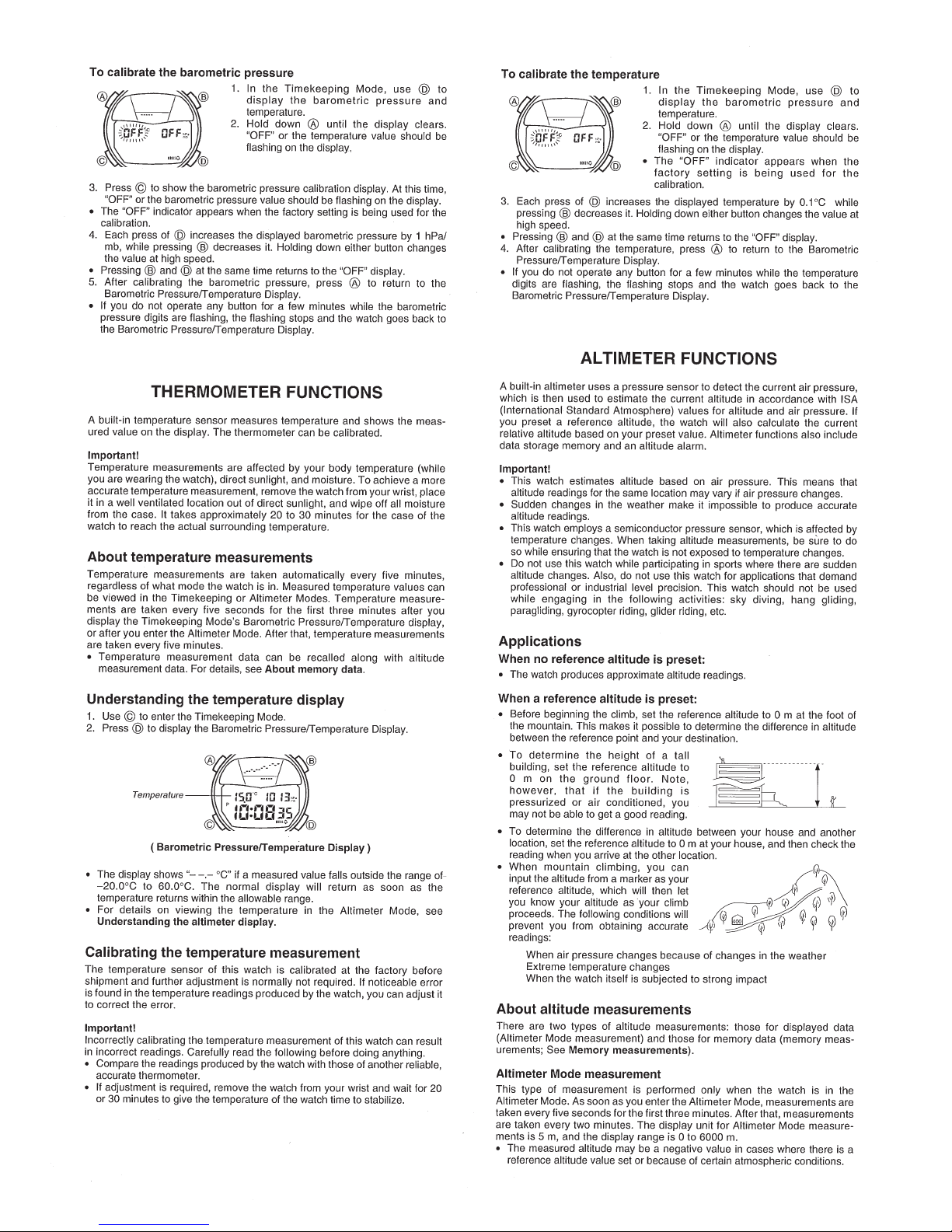
2. OPERATION CHART: QW-1664
— 2 —
Page 4

— 3 —
Page 5
— 4 —
Page 6

— 5 —
Page 7

— 6 —
Page 8

— 7 —
Page 9

— 8 —
Page 10

3. DRAWINGS
3-1. BLOCK DIAGRAMS: QW-1664
LC2
LC3
L 1
LC1
L 2
L18
L19
L 3
L 4
L 6
L 5
L10
L11
L13
L15
L14
L16
L 7
L 8
L 9
L12
L17
L20
L21
L22
L23
L24
5C1
5C2
57C1
57C5 56C5
57C2
56C4
55C5
54C5
55C4
54C4
56C2
56C3
55C3
54C3
56C1
55C2
4C1
55C1
54C2
53C5
53C4
LC1
LC2
LC3
LC5
LC4
LC4
LC5
LC3
3C2 2C2 1C2 61C2
4C2 21C2
48C1
51C2
52C5
52C4
51C3
51C5
51C4
52C1
52C2
50C1
51C1
50C2
50C3
49C3
50C4
49C1
49C2
48C3
49C5
50C5
49C4
53C1
54C1
53C2
53C3
52C3
48C2
48C4
47C2
48C5
47C4
60C2
47C3
47C5
59C2 58C2
46C3
46C5
45C1
46C1
45C2
46C2
45C3
L19L18L17L16L15L14L13L12L11L10L9L8L7L6
36C1
36C2
36C5
36C4
35C2
20C1
23C1
35C1
36C3
35C3
L20
L21L22L23L24L58L59L60L61L1L2L3L4L5
23C2
24C2
22C2
20C2
43C1
47C1
44C1
42C1
42C2
43C2
44C2
43C3
44C3
45C5
44C5
45C4
44C4
42C446C4
41C3
43C5
43C4
41C2
42C3
41C1
40C1
39C2
40C2
39C3
35C5
40C3
41C5
40C5
41C4
40C4
39C1
38C3
39C5
39C4
38C1
38C2
37C2
35C4
24C1
37C1
37C3
38C5
37C5
38C4
37C4
PZ
CT
C3
C2
C12
LC5
LC4
L61
L60
L59
L58
L57
L56
L55
L54
L53
L52
L51
L50
L49
L48
L47
L46
L45
L44
L43
L42
L41
L40
L39
L38
L37
L36
L35
❋3❋6
Xtal
XT
T1T2T3
AC
XTB
S1
KI1
S2
KI2
S3
KI3
SL
KI4
❋3
KI5
SK
KI6
❋5
VSS3
VC1
C1
VC2
VSS1
VCH
C4
LL1
Tr
BD
Z
LD
VDD
VSS2B ❋1
C11
VCCE
RT1
RT2
ENB
VCPE
GND
CIL
ELD
R
M_F
VSS2
BAT
LL2
Di
LC1
LC2
LC3
C_A
LSI ❋2
TOTAL 116 Pins
BONDING 109 Pins
A1A2A3A4VDDA
EL
INV
LC4
LC5
VSS2A
L1
VC3
VC4
VSS4
C5 C6 C7
OUTPUT (+)
— 9 —
VAN
4
SN3
RD RE
INPUT (+)
1
OUTPUT (–)
2
PS
3
INPUT (–)
VCOM
L61
VG
ISNS
SN1
SN2
IREF
VO4
VCO
VO6
VI6M
VA
VB
VADX
VADY
C10
C8
RA
RB
4
C9
❋4
3
2
PS
1
SN4
RTH
❋1. No bonding
❋2.
❋3. Short (Soldering)
❋4. PS:Sensor/Pressure
❋5. SK:Sensor/Tilt
❋6. Not short (No soldering)
RV1
RC
RV2
Page 11

3-2. CHECKING TERMINALS AND COMPONENTS: QW-1664
16. Transistor/Mold
Tr
(7101 1151)
4. Capacitor/Chip
C1
(7103 8080)
A1
VDD
A2
VDD
A3
KI4
VDD
VDD
A4
VC2
VC1
VDD
VSS1
VDD
VSS3
VDD
M_F
VDD
KI5
KI1
KI1
CT
9. Capacitor/Trimmer
(7103 0458)
8. Capacitor/Tantalum
C11
(7911 1260)
LL1
VSS2
VSS2
VSS2
VDD
VSS2
VSS2
VDD
VDD
VCH
KI4
KI1
Xtal
KI2
ELD
VADX
KI3
6. Capacitor/Tantalum
C7
(2895 1358)
VAN
VDD
VAN
SN4
SN3
VCO
VO4
P.C.B ass’y
VADY
VADX
VB
VADX VA
IREFRC
(Unrepairable)
KI6
C4
7. Capacitor/Tantalum
(7103 4895)
4. Capacitor/Chip
C3
(7103 8080)
C2
VDD
VDD
KI6
C_A
VDD
4. Capacitor/Chip
(7103 8080)
10. Coil
(7020 0490)
SN3 SN4
V06
RT1RT2
VDD
L
ELD
ISNS
IREF
VDD
BD
VDD
VSS4
VDD
XT
VDD
L
XTB
XT
VDD L
VDD
L
CIL
VSS2
VI6M
VC4
VCPE
VSS2
VC3
14. Oscillator/Quartz
(7110 0693)
Di
12. Diode
(7101 5609)
2. Capacitor/Chip
C8
(7103 4759)
11. Coil
LL2
(7020 5413)
13. Inverter
INV
(7100 7917)
CIL
KI2
VSS2
VSS2
CIL
ELD
VSS2
LD(ENB)
VDD
VCPE
RC
VDD
ISNS
SN2
SN1
IREF
RT1
RT2
SN2
KI3
R
15. Resistor/Chip
(7103 7450)
C12
3. Capacitor/Chip
(7103 7443)
C5
5. Capacitor/Tantalum
(7103 7422)
5. Capacitor/Tantalum
C6
(7103 7422)
Top view of P.C.B. ass'y Bottom view of P.C.B. ass'y
3-3. A1 ~ A4 PADS
Never solder or desolder these pads, because they have been selected best in the production line.
A new Module/without Movement (Sensor) as a spare parts will be supplied with factory adjustment
of these pads.
— 10 —
Page 12

4. EXPLODED VIEW: QW-1664
30 (7233 2244)
28 (7210 0191)
1 (7001 2762)
25 (7010 4624)
20 (7020 5798)
31 (7230 0595)
22 (7234 0945)
29 (7423 7014)
18 (7211 9631)
27 (7231 1295)
24 (7233 1855)
PCB ass’y (Unrepairable)
Sensor/Pressure (Unrepairable)
19 (7233 2243)
17 (7218 0878)
32 (7236 0224)
23 (7234 1408)
Battery/Lithium (CR 2016)
21 (7231 1281)
26 (7231 1770)
— 11 —
Page 13

5. PARTS LIST: QW-1664
-
-
-
Note: 1. Prices and specifications are subject to change without prior notice.
2. Spare parts are classified as follows according to their importance in after-sales service.
A Rank --------------------------B Rank --------------------------C Rank ---------------------------
3. Batteries in Bulk pack on the tray will be supplied from our Overseas Spare Parts Section under charge basis.
Batteries in Blister pack will be supplied from our Sales Department.
4. As for order/supply of spare parts, refer to the separate publication "GUIDEBOOK for spare parts supply".
Item Code No. Parts Name Specification Applicable Q R
70728181 Module/without Movement QW-1664SA01 DW-9100BJ A
1 70012762 LCD C1663-03P QW-1664SA01 1 A
2 71034759 Capacitor/Chip CM21W5R153K25AT QW-1664SA01 1 B
3 71037443 Capacitor/Chip CM21W5R472K25AT QW-1664SA01 1 B
4 71038080 Capacitor/Chip CM21Y5V334Z16AT QW-1664SA01 3 B
5 71037422 Capacitor/Tantalum F951A475MQAAQ2 QW-1664SA01 2 B
6 28951358 Capacitor/Tantalum F950J106MSAAQ2 QW-1664SA01 1 B
7 71034895 Capacitor/Tantalum F950G335MQACCB QW-1664SA01 1 B
8 79111260 Capacitor/Tantalum F930J106MAA QW-1664SA01 1 B
9 71030458 Capacitor/Trimmer TSF-2L2-120-4.2 QW-1664SA01 1 B
10 70200490 Coil ELT-3K004B QW-1664SA01 1 B
11 70205413 Coil ELT3K104B QW-1664SA01 1 B
12 71015609 Diode MA1010000L QW-1664SA01 1 B
13 71007917 Inverter MIP803000L QW-1664SA01 1 B
14 71100693 Oscillator/Quartz DT-26SJ QW-1664SA01 1 B
15 71037450 Resistor/Chip ERJ6GEYF364V QW-1664SA01 1 B
16 71011151 Transistor/Mold 2SD1824(TX) QW-1664SA01 1 B
17 72180878 Cushion Q412611-1 QW-1664SA01 1 C
18 72119631 Cushion / 506 Q49364-1 QW-1664SA01 2 C
19 72332243 Cushion/1663 Q457862-1 QW-1664SA01 1 C
20 70205798 EL EL-1405-A-01 QW-1664SA01 1 B
21 72311281 Holder/Battery Q352952A-1 QW-1664SA01 1 C
22 72340945 Housing Q150272B-1 QW-1664SA01 1 C
23 72341408 Housing/1663-1 Q150678-1 QW-1664SA01 1 C
24 72331855 Insulation seal Q453435-1 QW-1664SA01 1 C
25 70104624 Interconnector Q457890-1 QW-1664SA01 2 C
26 72311770 Plate/Main Q150464B-2 QW-1664SA01 1 C
27 72311295 Plate/Terminal Q352953A-1 QW-1664SA01 1 C
28 72100191 Pole Q41702B-1 QW-1664SA01 1 C
29 74237014 Sheet/Insulation Q456001-1 QW-1664SA01 1 C
30 72332244 Spacer/1663 Q457983-1 QW-1664SA01 1 C
31 72300595 Spring/Coil 1253-1 Q439218A-1 QW-1664SA01 2 B
32 72360224 Terminal/Battery – 1199 Q341452C-1 1 C
Battery/Lithium CR2016 1
Very Important
Important
Less important
For the prices and minimum order/supply quantities of the above parts, refer to the Parts Price List P.P.L.-523.
Notes: Q – Used quantity
R – Rank
— 12 —
Page 14

6. PRECAUTIONS FOR REPAIR: QW-1664
6-1. AC (ALL CLEAR) AND REMOVING OF MODULE
1. Perform AC (ALL CLEAR) when inserting a new battery, or else the memories and/ or counters may give
erratic displays.
Touch the AC contact and the positive (+) side of the battery or main plate with the metallic tweezers.
The contact should be made for about two seconds.
2. On removing of the module from the case, please insert the precision screw driver between the module
and the case pointed by an arrow.
AC
Metallic tweezers
6-2. ACCURACY CHECKING
Check the accuracy of the module with the quartz timer after switching the module to “ACCURACY
CHECKING MODE”.
The operations are shown below:
A) SWITCHING TO “ACCURACY CHECKING MODE”
Continuously push the A, C and D buttons at the same time at the normal time keeping mode.
Then all the segments are displayed and the LCD drive signals are changed to the static drive signal
of “32 Hz” so that you can check the accuracy with the quartz timer.
B) CANCELLATION OF THE “ACCURACY CHECKING MODE”
Push any button.
Then the display is returned to its original state.
NOTE: The “ACCURACY CHECKING MODE” will
automatically return to the regular mode
in 1 ~ 2 hour(s) without any operation.
A
C
B
D
— 13 —
Page 15

Ver. 1 : Jun. 2005
Correction of page 12
CASIO COMPUTER CO.,LTD.
Overseas Service Division
Shibuya-ku, Tokyo 151-8543, Japan
6-2, Hon-machi 1-Chome
 Loading...