

Page 1
Connector and Cable Specifications
58476
Revised: January 12, 2012
This appendix describes the Cisco ME 4924-10GE switch ports and the cables and adapters that you use
to connect the switch to other devices.
Connector Specifications
These sections describe the connectors used with the switch.
Connecting to 1000BASE-T Devices
When connecting the ports to 1000BASE-T devices, such as servers, workstations, and routers, you must
use a four-twisted-pair, Category 5, straight-through cable wired for 10BASE-T, 100BASE-TX, and
1000BASE-T.
When connecting the ports to other devices, such as switches or repeaters, you must use a
four-twisted-pair, Category 5, crossover cable. Be sure to use a four-twisted-pair, Category 5 cable when
connecting to a 1000BASE-T-compatible device.
APPENDIX
B
Note Use a straight-through cable to connect two ports only when one port is designated with an X. Use a
crossover cable to connect two ports when both ports are designated with an X or when both ports do
not have an X.
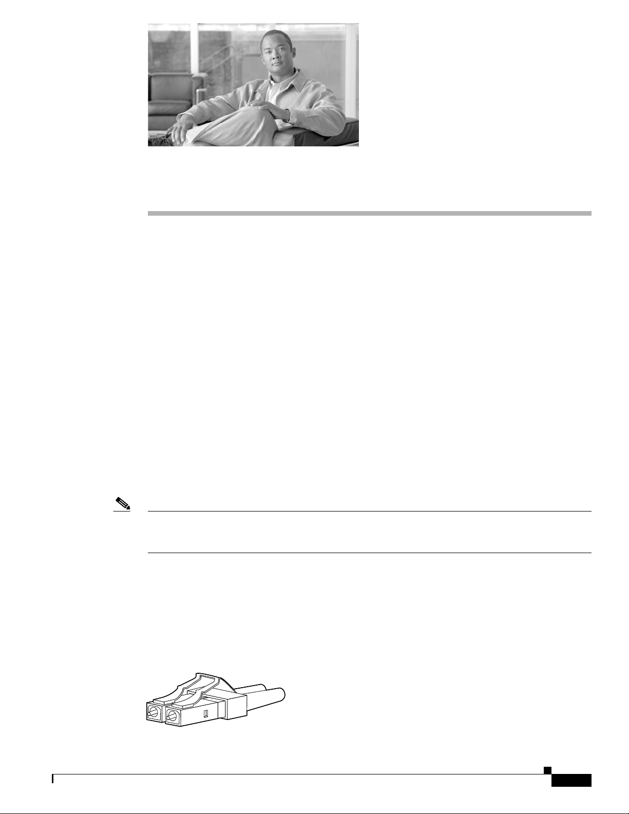
SFP Module Ports
The Cisco ME 4924-10GE switch uses SFP modules for fiber-optic and copper uplink ports. Refer to
the Cisco ME 4924-10GE switch release notes for a list of supported SFP modules.
Figure B-1 Fiber-Optic LC Connector
OL-10071-01
Cisco ME 4924-10GE Ethernet Switch Hardware Installation Guide
B-1
Page 2
Connector Specifications
60915
231 45678Pin Label
1
2
3
4
5
6
7
8
TP0+
TP0-
TP1+
TP2+
TP2-
TP1-
TP3+
TP3-
Appendix B Connector and Cable Specifications
REVIEW DRAFT—CISCO CONFIDENTIAL
Warning
Console Port
Invisible laser radiation may be emitted from disconnected fibers or connectors. Do not stare into
beams or view directly with optical instruments.
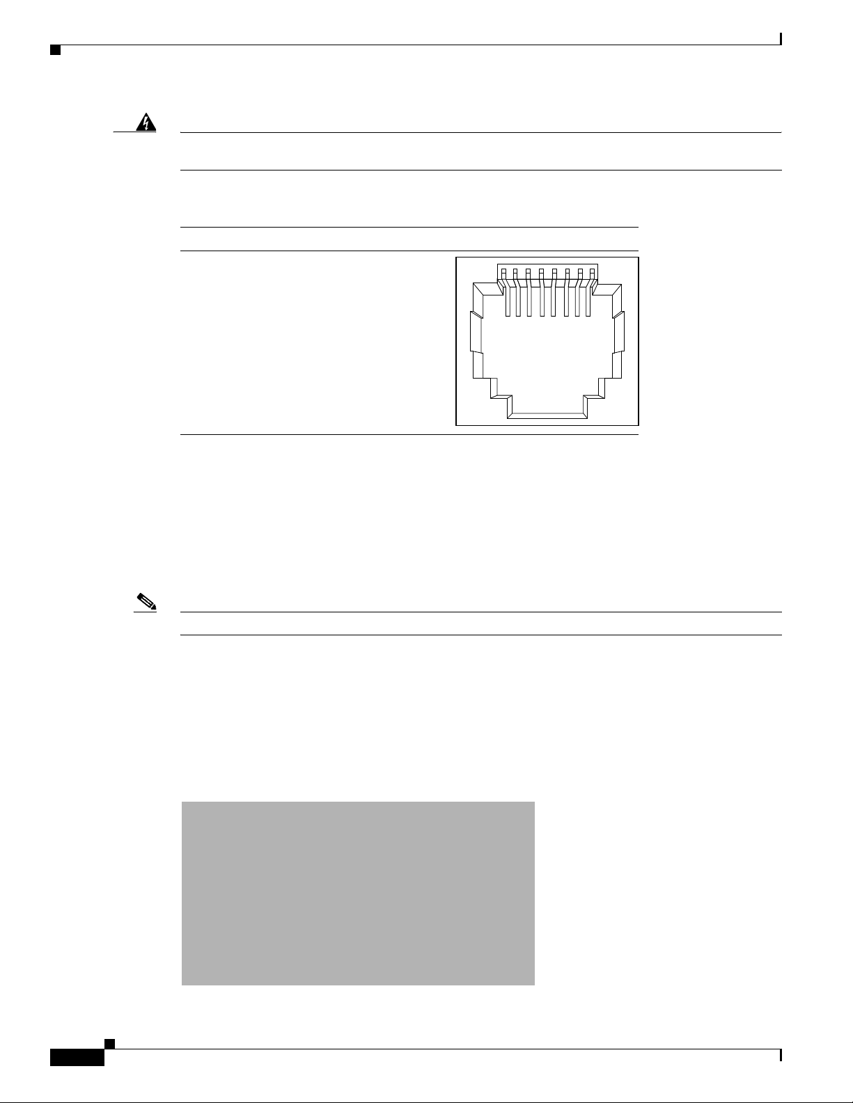
Figure B-2 Copper SFP Module RJ-45 Connector
The console port uses an 8-pin RJ-45 connector, which is described in Ta ble B-1 and Table B- 2 . An
RJ-45-to-DB-9 adapter cable is used to connect the console port of the switch to a console PC. You need
to provide a RJ-45-to-DB-25 female DTE adapter if you want to connect the switch console port to a
terminal. You can order a kit (part number ACS-DSBUASYN=) containing that adapter from Cisco.
Note A console cable is not provided in the accessory kit. It can be ordered as an option.
Identifying a Crossover Cable
To identify a rollover cable, compare the two modular ends of the cable. Hold the cable ends
side-by-side, with the tab at the back. The wire connected to the pin on the outside of the left plug should
be the same color as the wire connected to the pin on the outside of the right plug. (See Figure B-3.)
Figure B-3 Identifying a Crossover Cable
B-2
Cisco ME 4924-10GE Ethernet Switch Hardware Installation Guide
OL-10071-01
Page 3

Appendix B Connector and Cable Specifications
Cable and Adapter Specifications
These sections describe the cables and adapters used with the Cisco ME 4924-10GE switch.
Adapter Pinouts
Table B- 1 lists the pinouts for the console port, the RJ-45-to-DB-9 adapter cable, and the console device.
Table B-1 Console Port Signaling Using a DB-9 Adapter
Switch
Console
Port (DTE)
Signal DB-9 Pin Signal
RTS 8 CT S
DTR 6 DSR
TxD 2 RxD
GND 5 GND
GND 5 GND
RxD 3 TxD
DSR 4 DTR
CTS 7 RTS
RJ-45-to-DB-9
Terminal Adapter
Console
Device
Cable and Adapter Specifications
Table B- 2 lists the pinouts for the console port, RJ-45-to-DB-25 female DTE adapter, and the console
device.
Note The RJ-45-to-DB-25 female DTE adapter is not supplied with the switch. You can order a kit (part number
ACS-DSBUASYN=) containing this adapter from Cisco.
Table B-2 Console Port Signaling Using a DB-25 Adapter
Switch
Console
Port (DTE)
Signal DB-25 Pin Signal
RTS 5 CT S
DTR 6 DSR
TxD 3 RxD
GND 7 GND
GND 7 GND
RxD 2 TxD
RJ-45-to-DB-25
Terminal Adapter
Console
Device
OL-10071-01
Cisco ME 4924-10GE Ethernet Switch Hardware Installation Guide
B-3
Page 4

Console Port
Table B-2 Console Port Signaling Using a DB-25 Adapter (continued)
Switch
Console
Port (DTE)
Signal DB-25 Pin Signal
DSR 20 DTR
CTS 4 RTS
Console Port
The console port is an RJ-45 receptacle. The Request to Send (RTS) signal tracks the state of the Clear
to Send (CTS) input. Tab le B-3 lists the console port pinouts.
Table B-3 Console Port Pinouts
Pin Signal Direction Description
1 RTS output request to send
2 DTR output data terminal ready
3 TXD output transmit data
4GND — —
5GND — —
6 RXD input receive data
7 DSR input data set ready
8 CTS input clear to send
Appendix B Connector and Cable Specifications
REVIEW DRAFT—CISCO CONFIDENTIAL
RJ-45-to-DB-25
Terminal Adapter
Console
Device
B-4
Cisco ME 4924-10GE Ethernet Switch Hardware Installation Guide
OL-10071-01
 Loading...