

Casio PRT-40C, MWA-800G, ABX-68B Repair Manual
W ATCH BASIC
REPAIR MANUAL
(RANKS A AND B)
JULY 1997
PRT-40C
(QW-1470)
ABX-68B
(QW-1359)
MWA-800G
(QW-1325)
R

BASIC REPAIR MANUAL
(Ranks A and B)
Definition of Ranks B:
<Digital>
Ranks B refers to the level at which technical skills and tools are possessed that enable
evaluation of the quality of all parts at the individual part level, replace or adjust those parts
and perform waterproof inspections, excluding watches equipped with a sensor and the
Professional Diver’s Watches.
<Analog>
Ranks B refers to the level at which technical skills and tools are possessed that enable
evaluation of the quality of all parts at the individual part level, replace or adjust those parts
and perform waterproof inspections, excluding the train wheel unit.
Definition of Ranks A:
Ranks A refers to the level at which technical skills and tools are possessed that enable
evaluation of the quality of all parts of all watches at the individual part level, replace or adjust
those parts and perform waterproof inspections, excluding the Professional Diver’s Watches.
CONTENTS
FLOW CHART FOR REPAIR OF MODULE WITHOUT MOVEMENT............................ 1
FLOW CHART FOR REPAIR OF MODULE WITH MOVEMENT ................................... 2
FLOW CHART FOR REPAIR OF CASING PARTS ........................................................ 3
1. Circuit Explanation of Quartz Watches ............................................................... 4
1-1 Circuit Diagram.............................................................................................................. 4
1-2 Digital Quartz Watches .................................................................................................. 5
1-3 Analog Watches............................................................................................................. 5
2. Measurement of Current Consumption (Oscillation Check) ............................. 6
3. Quality Evaluation and Replacement of Electronic Parts.................................. 8
3-1 Capacitors/Chip .............................................................................................................8
3-2 Transistors ..................................................................................................................... 9
3-3 Coils...............................................................................................................................9
3-4 Oscillators/Quartz ..........................................................................................................9
4. Accuracy Setting Method for Casio Watches ................................................... 10
4-1 Accuracy Setting by Capacitor/Trimmer ...................................................................... 10
4-2 Accuracy Setting by Pad Selection.............................................................................. 11
4-3 Digital Tuning (Pattern Cutting) Method ...................................................................... 11
5. LCD Replacement................................................................................................ 12

6. Quality Evaluation and Replacement of EL....................................................... 12
7. Names of Casing Parts ....................................................................................... 14
7-1 G-Shock....................................................................................................................... 14
7-2 Baby-G......................................................................................................................... 15
7-3 Twincept....................................................................................................................... 16
7-4 Data Bank.................................................................................................................... 17
7-5 Diver's Watch...............................................................................................................18
7-6 Watches Equipped with a Sensor/Pressure (Side Sensor) ......................................... 19
7-7 Watches Equipped with a Sensor/Pressure (Front Sensor) ........................................ 20
8. Replacement of Casing Parts ............................................................................. 21
8-1 Glass Replacement ..................................................................................................... 21
8-2 Button Replacement .................................................................................................... 22
8-3 Register Ring Replacement......................................................................................... 23
8-4 Piezo Replacement ..................................................................................................... 23
9. Analog Block Replacement ................................................................................ 24
10. Waterproof Inspection......................................................................................... 26
10-1 Water Resistant Tester .............................................................................................. 27
10-2 Air Leak Checker ....................................................................................................... 28
10-3 Water Pressure Tester and Hot Plate ........................................................................ 30
11. Quality Evaluation and Replacement of Sensor/Pressure .............................. 32
11-1 Trouble Shooting with Sensor/Pressure Trimming Jig Set......................................... 33
11-2 Trouble Shooting without Sensor/Pressure Trimming Jig Set.................................... 34
11-3 Sensor/Pressure Quality Evaluation.......................................................................... 35
11-4 Removal and Attachment of Sensor/Pressure ........................................................... 35
11-4-1 Sensor/Pressure Equipped on Side of the Watch .................................................. 35
11-4-2 Sensor/Pressure Equipped on Front of the Watch ................................................. 36
12. Altimeter of Watches Equipped with a Sensor/Pressure................................. 36
13. Quality Evaluation and Replacement of Sensor/Magnetic .............................. 37
13-1 When a Watch Does Not Indicate Directions Correctly ............................................. 37
13-2 Quality Evaluation of Sensors/Magnetic .................................................................... 37
13-3 Quality Evaluation of Sensors/Magnetic .................................................................... 38
14. Quality Evaluation and Replacement of Coil Ass'y .......................................... 38
15. Repair of Module/with movement ...................................................................... 39
15-1 Precautions when Repairing Modules/with movement.............................................. 39
15-2 The Structure and Names of Parts of Module/with movement .................................. 40
15-3 Explanation of Each Part of Module/with movement ................................................. 42
15-3-1 Train Wheel Part..................................................................................................... 42
15-3-2 Correction Part ....................................................................................................... 42
15-3-3 Calendar Part ......................................................................................................... 43
15-4 Disassembly, Cleaning, Lubrication and Reassembly of Module/with movement ..... 44
15-4-1 Disassembling ........................................................................................................ 44

15-4-2 Cleaning .................................................................................................................44
15-4-3 Lubrication and Reassembly .................................................................................. 45
15-4-4 Confirmation ........................................................................................................... 46
16. Clock Repair (Heat Seal Replacement).............................................................. 46
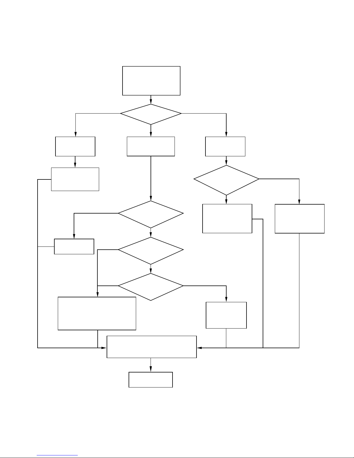
FLOW CHART FOR REPAIR OF MODULE WITHOUT MOVEMENT
(RANKS A AND B)
Module without
Movement is broken
What is wrong ?
Yes
EL doesn’t light
Refer to 6. Quality
evaluation and
replacement of EL
Yes
Refer to 5. LCD
replacement
Replacement of PCB ass’y
or replacement of
each components. (Refer to
3. Quality evaluation and
replacement of electronic parts.)
Yes
No good
Display trouble
LCD is broken ?
No
Battery have
much power
No
Current
consumption is
OK ?
Refer to
2. Measurement of
current consumption
(Oscillation check)
Good
Sensor trouble
Sensor/pressure ?
Sensor/magnetic ?
Sensor/pressure
Refer to 11. Quality
evaluation and
replacement of
sensor/pressure
Refer to Watch
Basic Repair
Manual (Ranks
C and D)
Sensor/magnetic
Refer to 13. Quality
evaluation and
replacement of
sensor/magnetic
(In case the watch is water resistant)
Refer to 10. Waterproof inspection.
Water resistant inspection
Repair is finished
— 1 —
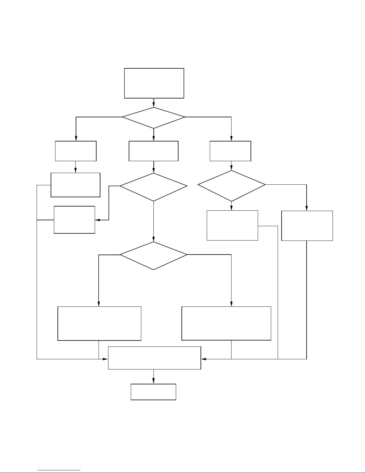
FLOW CHART FOR REPAIR OF MODULE WITH MOVEMENT
Module with
Movement is broken
What is wrong ?
Battery have
much power
Current
consumption is
OK ?
Sensor/pressure ?
Sensor/magnetic ?
EL doesn’t light
Refer to 6. Quality
evaluation and
replacement of EL
Refer to Watch
Basic Repair
Manual (Ranks
C and D)
Sensor trouble
Hands are not
moving
Replacement of PCB ass’y
or replacement of
each components. (Refer to
3. Quality evaluation and
replacement of electronic parts.)
Repair of mechanical portion.
Refer to 9. Analog blcok
replacement, 14. Quality evaluation
and replacement of coil ass'y and
15. Repair of module/with movement.
Water resistant inspection
(In case the watch is water resistant)
Refer to 10. Waterproof inspection.
Repair is finished
Refer to 11. Quality
evaluation and
replacement of
sensor/pressure
Refer to 13. Quality
evaluation and
replacement of
sensor/magnetic
Refer to
2. Measurement of
current consumption
(Oscillation check)
Sensor/pressure
Sensor/magnetic
Yes
Yes
Good
No
No good
(RANKS A AND B)
— 2 —
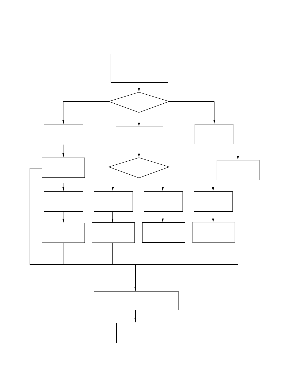
FLOW CHART FOR REPAIR OF CASING PARTS
(RANKS A AND B)
Band or Dial are
broken
Refer to Watch
Basic Repair Manual
(Ranks C and D)
Glass is broken Button is broken
The casing parts of watch
is broken
What is wrong ?
Yes
Case/Center ass'y is
broken
Which part is
broken
Register ring is
broken
Alarm doesn't
sound
Refer to 8-4. Piezo
replacement
Case is broken
Refer to 8-1. Glass
replacement
Refer to 8-2. Button
replacement
Water resistant inspection
(In case the watch is water resistant)
Refer to 10. Waterproof inspection.
Repair is finished
Refer to 8-3. Register
ring replacement
— 3 —
Refer to Watch Basic
Repair Manual
(Ranks C and D)
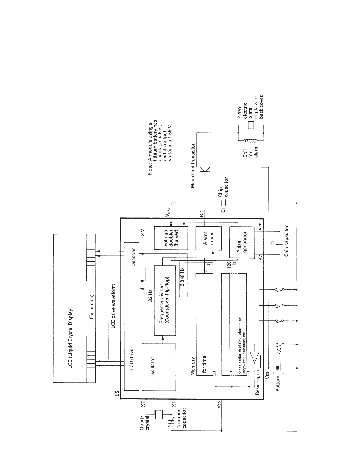
1. Circuit Explanation of Quartz Watches
The basic circuits employed in quartz watches are as described below. Nearly all portions of these
circuits are contained in the LSI, and therefore cannot be repaired. (Fig. 1-1) However, they are
important in terms of understanding the operating principle of the quartz watches.
1-1 Circuit Diagram
Fig. 1-1
— 4 —
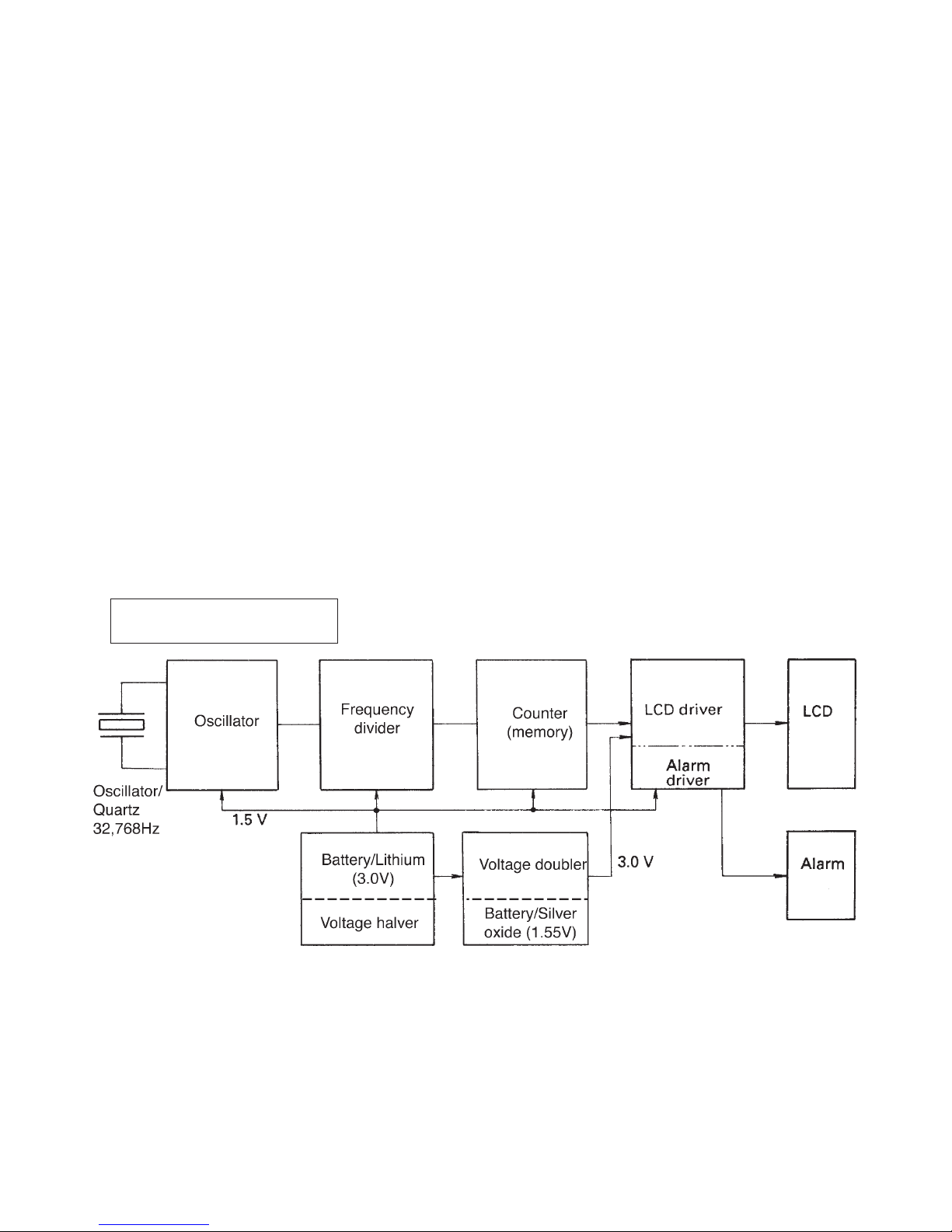
1-2 Digital Quartz Watches
Power Unit (Battery):
There are two types of batteries: a battery/lithium (3.0 V, mainly used in digital watches), and a battery/
silver oxide (1,55V, mainly used in analog watches). In addition, since the driving voltage of the LCD
driver is 3 V and that of the oscillator is 1.5 V, a voltage halver (for the oscillator) is provided in the LSI
of the modules using a battery/lithium, while a voltage doubler (for driving the LCD) is provided in the
LSI of the modules using a battery/silver oxide.
Oscillator:
This circuit generates a 32,768 Hz signal with the oscillator/quartz and capacitor/trimmer.
Frequency divider:
This circuit converts the 32,768 Hz signals produced with the oscillation circuit to 1 Hz signals with
Count Down Flip Flop.
Counter (memory):
This circuit controls the counting of time, calendar and stopwatch functions, etc. based on the 1 Hz
signals produced by the dividing circuit.
Driver:
This circuit drives the LCD, alarm, EL and so forth.
DIGITAL QUARTZ WATCH
Fig. 1-2
1-3 Analog W atches
Oscillator and Frequency divider:
These circuits function in the same manner as in digital watches.
Coil driver:
This circuit provides a 1 Hz alternating current (signal) to the coil of the analog block.
— 5 —
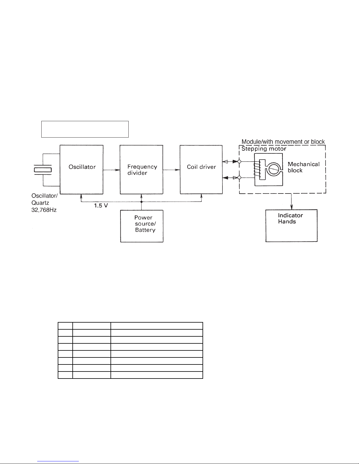
Stepping Motor:
This is composed of a coil, stator and rotor. This motor turns the rotor 180 degrees per second when
the 1 Hz alternating current signal is received from the coil driver, resulting in rotation of the gears of
the train wheel unit. Operation beyond this point is performed by the mechanical portion.
Mechanical block:
This unit moves the hands and calendar wheel as a result of its gears being turned by the motive force
from the rotor.
ANALOG QUARTZ WATCH
Fig. 1-3
2. Measurement of Current Consumption (Oscillation Check)
Tool used
NO. Code No. Tool name
1 1904 5153 HP-fingerstall
2 1902 0974 Battry checker
3 1904 5277 Multimeter
4 1901 9523 Precision tweezers
5 Lead wire
6 Alligator clip
7 IC clip
In cases when the battery life of a watch appears to be extremely short, it is possible that current
consumption has increased abnormally due to circuit shorts, defective parts or other problems.
When this happens, the quality of the module can be evaluated by measuring current consumption.
In addition, in the case of analog watches, it is possible to determine whether the location of the
malfunction is in the electronic portion or mechanical portion of the watch by measuring current consumption (oscillation check).
— 6 —
The measurement procedure is described below.
1) Remove the cover/back and take out the battery. (Use a plastic tweezers or finger stall.)
2) After checking that the battery still has sufficient charge with a battery checker, place the battery
on the plate/main of the module with the plus side facing down.
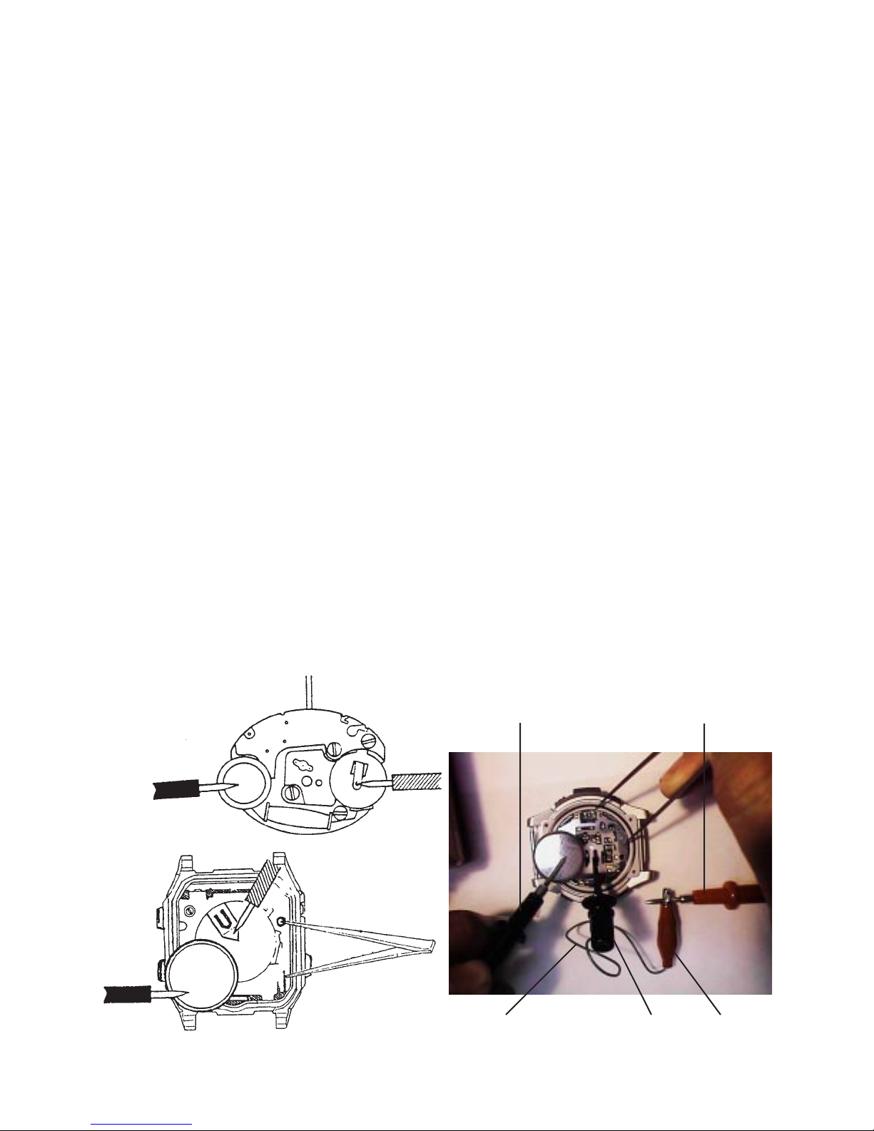
3) After setting the measurement range of the analog multimeter to an alternating current range of 30
or 50 µA, place the plus end of the probe (colored red) on the battery (minus side) and place
the minus end (colored black) on the battery contact (–) of the module/with movement. (Fig.
2-1)
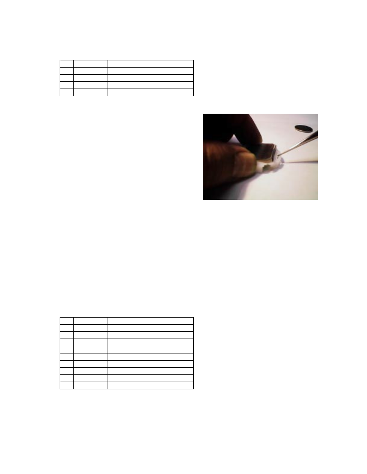
4) Although the procedure up to step 3) is satisfactory for analog watches, in the case of digital and
combination watches, the AC operation is performed with the watch left in the state in step 3) .
(Fig. 2-2)
In the case of performing this procedure alone, since it is difficult to perform the AC operation with
one hand while holding the two tester probes with the other hand, this can be done easier by using
that which has an alligator clip and IC clip attached to the lead wires. (Fig. 2-3)
5) In the case of digital and combination watches, current consumption can be considered to
be normal if the needle on the multimeter points to between roughly 3 and 10 µA. In the
case of analog watches, current consumption can be considered to be normal if the needle
on the multimeter deflects between roughly 0 and 10 µA every second.
Current consumption differs according to the module. Refer to the List of Current Consumption for
each module in the Watch Index Book for the proper current consumption value of each model.
6) In the case of analog watches, if the needle deflects normally as described in 5) above, it can be
assumed that 1 Hz signal is reaching the coil ass'y of the stepping motor. Thus, when repairing
an analog watch that has malfunctioned with the hands stopped, first try measuring current
consumption. If current consumption is found to be normal, it means that the cause of the mal-
function lies in the mechanical portion (past the rotor). Conversely, if current consumption is found
to be abnormal, this means that the cause of the malfunction lies in the electronic circuits and coil
ass'y.
Black
Red
Black
Fig. 2-1
Fig. 2-2
Red
— 7 —
Lead wire
Red probeBlack probe
Fig. 2-3
IC clip Alligator clip
3. Quality Evaluation and Replacement of Electronic Parts
Tool used
NO. Code No. Tool name
1 1904 5153 HP-fingerstall (two set)
2 1904 5277 Multimeter
3 1901 9523 Precision tweezers
4-1 1904 1667 Soldering iron (110 V/117 V)
4-2 1904 1668 Soldering iron (220 V)
5 1901 9868 Solder wick
6 1901 9401 Solder
7 Lead wire
8 Alligator clip
9 IC clip
Ceramic
Terminals
for solder
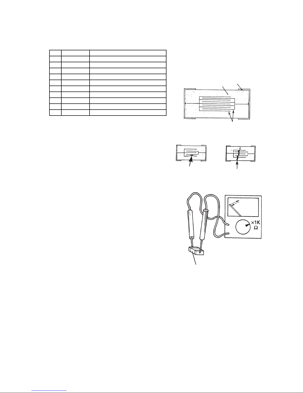
3-1 Capacitors/Chip
Capacitors/chip consist of two extremely thin metal plates
(electrodes), combined as shown in the drawing, surrounded by a ceramic covering. The function of the capacitor/chip is to store electrical charge. (Fig. 3-1) It has
the characteristic of allowing the flow of alternating current but not direct current.
The capacitors/chip may be damaged by an internal short
circuit to crack. (Fig. 3-2)
In quartz watches, capacitors/chip are typically used in
the voltage doubling circuits (VSS1, VSS2, VSS3) that
produce the driving voltage for the LCD display, and in
the pulse generators (VC, VCC/VC1, VC2) for driving the
LSI or in the power supply (VCH) for the LSI block. In
addition, as one method of adjusting the accuracy of the
watch, a capacitor/chip is selected corresponding to the
variation in accuracy of the oscillator/quartz instead of a
capacitor/trimmer. Quality evaluation of capacitors/chip
is performed using a multi-meter according to the following procedure.
1) Remove the capacitor/chip to be inspected from the P.C.B.
2) Set the multimeter to the 1 KΩ or 10 KΩ range.
3) Place the probe of the multimeter against two electrodes of the capacitor/chip to observe the state
of charging and discharging. If the capacitor/chip is acceptable, the multimeter will display a certain constant resistance value since electricity initially is charged within the capacitor/chip (the
resistance value varies according to the type of capacitor/chip). When charging is completed, the
resistance value reaches infinity, and the needle returns to its original position. (Fig. 3-3) If the
capacitor/chip is defective, the needle will point to 0 Ω (indicating a short) or remain at ∞ (indicating
an open circuit).
Capacitor/Chip
Fig. 3-1
CrackShort circuit
Fig. 3-2
Fig. 3-3
— 8 —
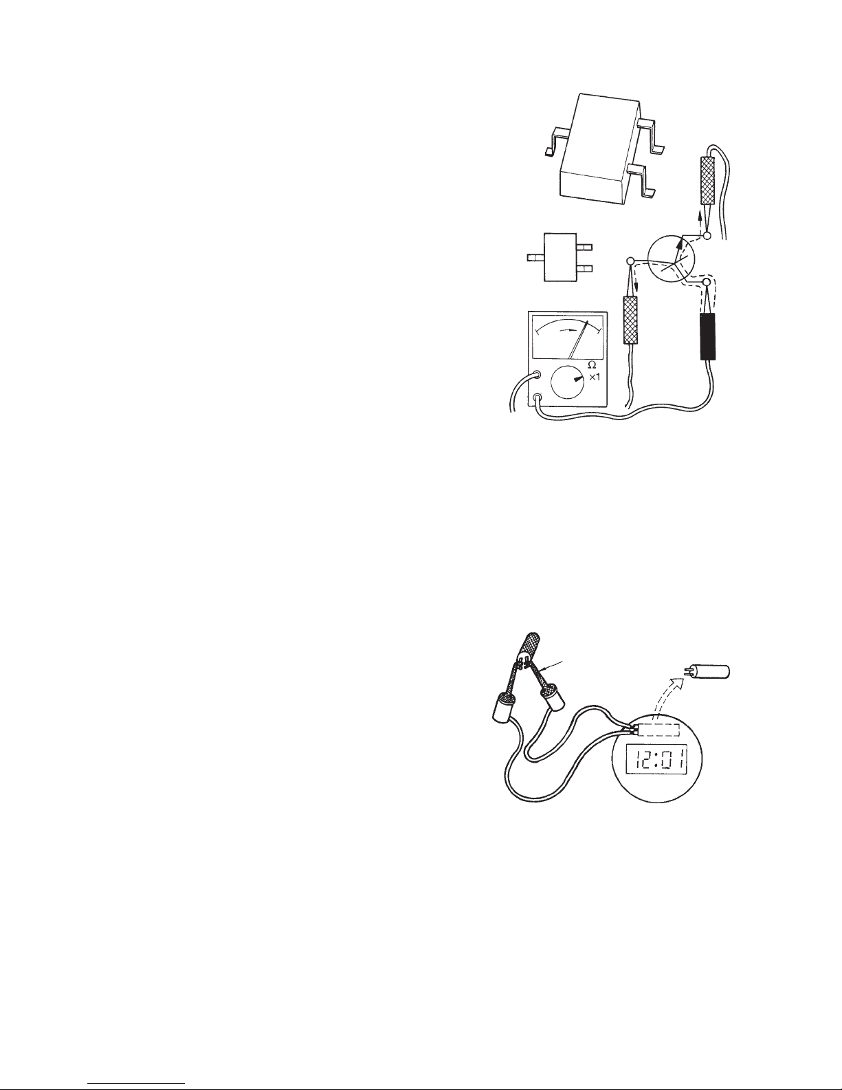
3-2 Transistors
In watches, transistors are mainly used to perform signal
amplification in the alarm (BD) and EL (LD) drive circuits.
Evaluation of their quality is performed as described below.
1) Remove the transistor to be inspected from the P.C.B.
2) Set the multimeter to the 1 KΩ or 10 KΩ range.
3) Measure the resistance between the base (B) and emitter (E), and between the base (B) and collector (C). If
the transistor is acceptable, the respective resistance values will be in the range of 50-200 Ω. (Fig. 3-4)
3-3 Coils
E
C
B
NPN
E
C
C
B
E
B
Coils are used to increase voltage and so forth for generating the driving voltages for the alarm and EL. Evaluation of
their quality is performed as described below.
1) Remove the coil to be inspected from the P.C.B.
2) Set the multimeter to the 1 KΩ or 10 KΩ range.
3) Measure the resistance value. If the coil is acceptable, the resistance value will be in the range of
80-150 Ω .
Fig. 3-4
3-4 Oscillators/Quartz
Oscillators/quartz produce a stable 32,768 Hz signal with
the oscillation circuit in the LSI. The most effective way
to evaluate the quality of a oscillator/quartz is to use a
dummy watch for checking oscillators/quartz. The procedure for making a dummy watch is described below.
1) Have available a digital watch (preferably of the solar
battery type that does not require AC operation).
2) Disassemble the module and remove the oscillator/
quartz from the PCB ass’y.
3) Solder lead wires to the terminals to which the oscillator/quartz was soldered (XT, XTB), and reassemble
the watch with the wires extending outside the watch.
4) Attach IC clips, etc. to the terminals of the lead wires. (This completes the dummy watch.)
5) When desiring to check a oscillator/quartz, first remove that oscillator/quartz from the PCB ass’y,
and attach the IC clips of the dummy watch to its legs. If the dummy watch starts to run normally,
it means that the oscillator/quartz being checked is not defective.
Clip
Dummy module
Fig. 3-5
— 9 —
4. Accuracy Setting Method for Casio Watches
)
Although the oscillation frequency of the oscillator/quartz used in watches is said to be 32,768 Hz, in
actuality there is a slight degree of variation between individual oscillators/quartz. Accuracy setting is
required in order to maintain the accuracy claimed in the specifications of watches using these oscillators/quartz.
This accuracy setting procedure is naturally also required when a oscillator/quartz has been replaced
during repairs.
The following provides a description of the accuracy setting method for Casio watches.
4-1 Accuracy Setting by Capacitor/Trimmer
Tool used
NO. Code No. Tool name
1 Quartz timer
2 1901 9523 Precision tweezers
3-1 1704 1667 Soldering iron (110 V/117 V)
3-2 1904 1668 Soldering iron (220 V)
4 1901 9868 Solder wick
5 1901 9401 Solder
6 1901 9975 Ceramic screw driver (small
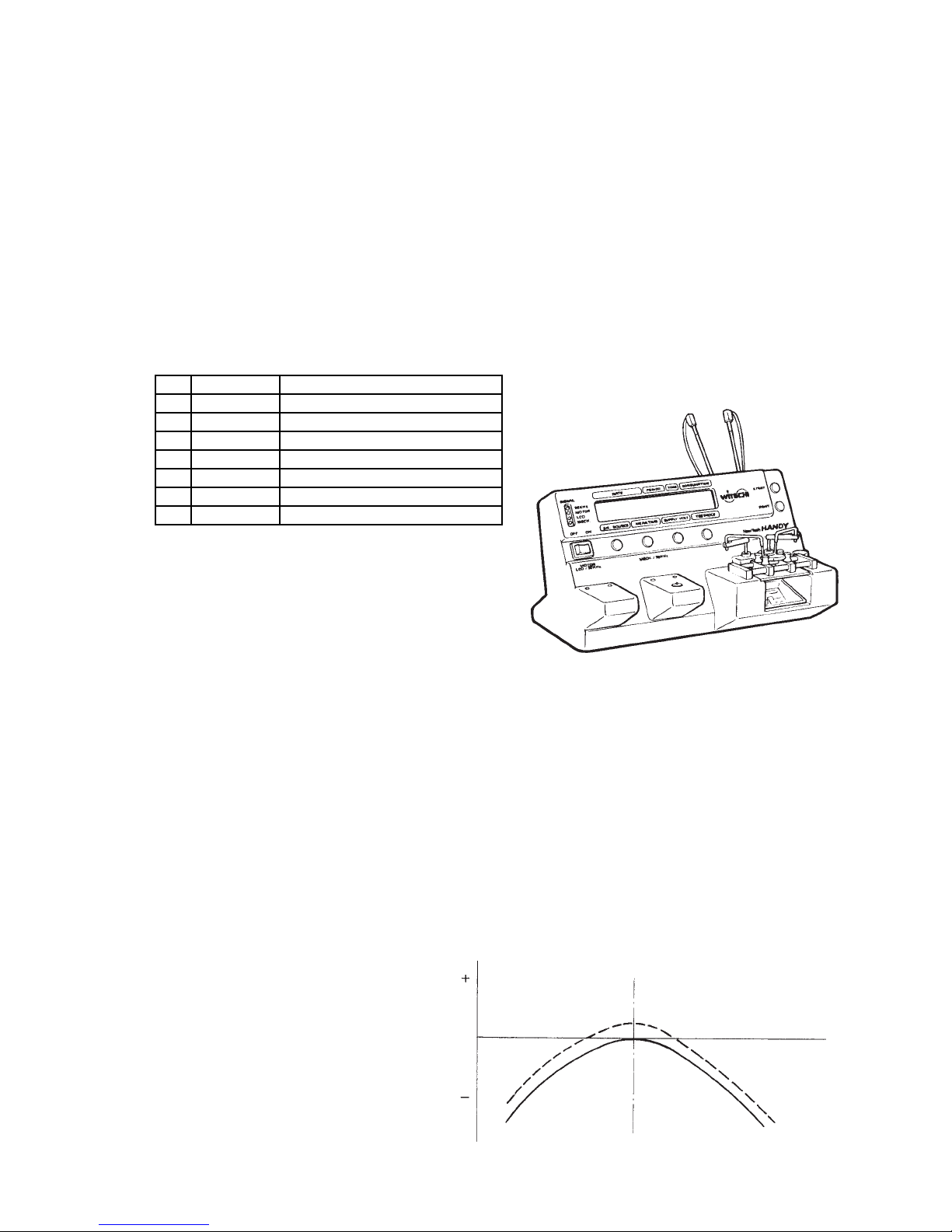
The capacitor/trimmer is a capacitor equipped with a
volume that enables the capacitance to be varied.
When the accuracy of a watch is measured with a
quartz timer and the accuracy is found to be incorrect, accuracy can be adjusted by turning the volume
of the capacitor/trimmer.
This procedure must always be performed when the watch no longer keeps the correct time or after
the oscillator/quartz has been replaced. Furthermore, the accuracy (monthly) and setting range (daily)
of each watch (module) is indicated in the Specifications of the Service Manual or the List of Current
Consumption in Watch Index Book.
In the case of a watch accurate to a monthly error of ±15 seconds, the daily error is normally set to a
range of +0.25 to +0.35 seconds.
This is done in consideration of the temperature characteristics of the oscillator/quartz. Even if the
watch were set to be accurate to a daily error of ±0 seconds, the watch would end up running slow at
atmospheric temperatures outside the vicinity of 25 °C. Watches are therefore set to a range of +0.25
to +0.35 seconds at the outset to enable them to maintain a constant accuracy (±15 seconds) within
an atmospheric temperature range of 0-40 °C. (Fig. 4-2)
Quartz timer
Fig. 4-1
32,768=0
— 10 —
25 °C
°C
Fig. 4-2
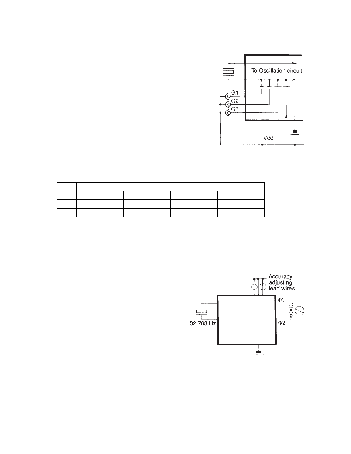
4-2 Accuracy Setting by Pad Selection
The capacitance of the capacitor in the LSI can be
changed to nine different levels by combining the
open and shorted states of pads G1-G3 of the PCB
ass’y. (Fig. 4-3)
These changes in capacitance can be used to adjust the accuracy.
The combinations of these pads are as shown in
the following chart.
Although they can be adjusted during repairs, since
it is necessary to disassemble and reassemble the
module each time the rate is adjusted, this procedure is actually quite difficult.
Thus, in the case a watch no longer runs accurately
or a oscillator/quartz has been damaged in modules for which accuracy setting is performed in this
manner, it is preferable that repairs are performed by replacement of the PCB ass’y or module.
(+) Side, Gain <----- ACCURACY (Sec./ Day) -----> (–) Side, Lose
G1 Open (Close) (Open) (Close) Open (Close) Open Close
G2 Open (Open) (Close) (Close) Open (Open) Close Close
G3 Open (Open) (Open) (Open) Close (Close) Close Close
Oscillator/Quartz
Fig. 4-3
Notes: "Close" means the lead wire is connected (or soldered).
"Open" means the lead wire is cut (or not soldered).
4-3 Digital Tuning (Pattern Cutting) Method
This method is used for analog watches
(and mainly those of the two hand type).
Even if the oscillation frequency is not
32,768 Hz, a constant accuracy is maintained by adjusting the alternating current
signals that forcibly enter the coil. That
adjustment procedure is performed by
cutting lead wires (3-5) on the P .C.B. (Fig.
4-4)
The combination of cuts are also varies
according to the oscillator/quartz.
Thus, in the case the oscillator/quartz has
been damaged in a module in which this
rate setting method is employed, replacement must be performed from the PCB ass’y or module.
Furthermore, when checking the accuracy with a quartz timer, checking should be performed at
a gate time of 10 seconds.
Oscillator/Quartz
Fig. 4-4
— 11 —
5. LCD Replacement
Tool used
NO. Code No. Tool name
1 1904 5153 HP-fingerstall (two set)
2 1901 9672 Precision screwdriver set
3 1901 9523 Precision tweezers
4 1901 9519 Blower brush
When the LCD is missing characters, there are many
cases in which this is repaired by replacing the LCD.
In addition, the LCD is also replaced when it is
cracked. The LCD is replaced according to the
procedure described below.
1) Remove the module from the case.
2) Remove the hooks of the plate/main, and separate housing-1 and housing-2.
3) Remove the PCB ass’y from housing-1.
4) Turn the housing-1. And insert the end of a tweezers into the hooks that hold down the LCD of
housing-1, remove the hooks and remove the LCD
from housing-1. (Fig. 5-1)
5) When installing the new LCD, install the LCD while spreading apart the hooks of housing-1 with the
end of a tweezers and then secure the LCD in position by catching the hooks on the LCD.
6) Reassemble the module.
Fig. 5-1
6. Quality Evaluation and Replacement of EL
Since the EL has an impedance of ∞ and capacitance of 1,500 PF, quality cannot be evaluated by
measuring using a multimeter.
Therefore a module equipped with an EL is modified according to the following procedure to prepare
an EL checker that is used in quality evaluations.
Tool used
NO. Code No. Tool name
1 1904 5153 HP-fingerstall (two set)
2 1901 9672 Precision screwdriver set
3 1901 9523 Precision tweezers
4-1 1704 1667 Soldering iron (110 V/117 V)
4-2 1904 1668 Soldering iron (220 V)
5 1901 9868 Solder wick
6 1901 9401 Solder
7 Lead wire
8 Alligator clip
— 12 —
 Loading...