

Page 1
INSTALLATION, OPERATION & MAINTENANCE MANUAL (IOM)
MODEL SCV-S
GLOBE-STYLE - SANITARY
PNEUMATIC CONTROL VALVE
BODY IOM
SECTION I
I. DESCRIPTION AND SCOPE
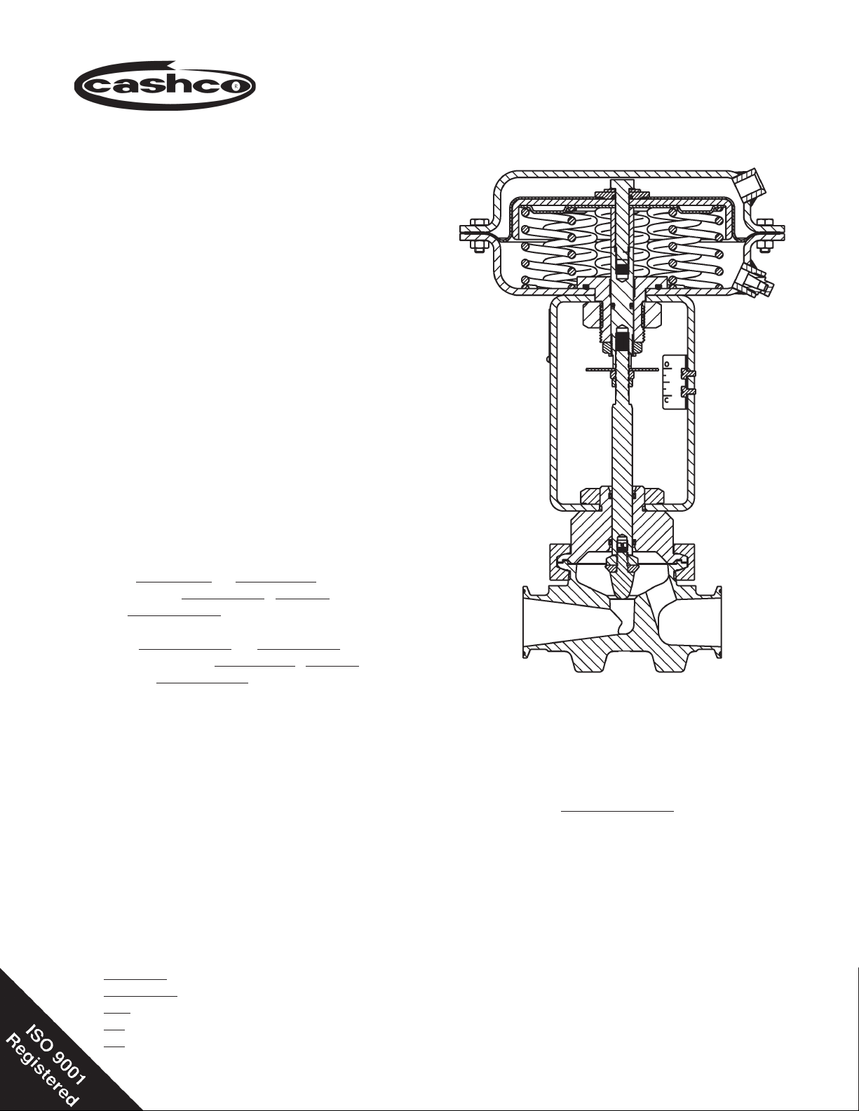
Model SCV-S is a pneumatically actuated, globe-style
con trol valve for throttling sanitary or biotechnological
ap pli ca tions. The globe body comes in two variations
- straight-globe pattern and angle-globe pattern, sizes
3/4" - 1-1/2" (DN20 - DN40) with standard Tri-Clover®
sanitary end connections. The valve is available in
either a metal or composition seat construction. The
wetted metallic body portion is of forged 316L SST
mechanically and electro-polished to a 10 micro-inch
Ra fi nish.
IOM-SCV-S
12-13
A fi eld reversible actuator, Model C27 is mounted
to the body.
Failure position is determined by actuator for:
"D" = Direct action; on increasing air loading pressure,
the actuator stem extends. Fail-safe position is with
the stem retracted.
"R" = Reverse action; on increasing air loading pres-
sure, the actuator stem retracts. Fail-safe position is
with the stem extended.
The standard actuator stem-to-valve stem connection
is a screwed joint design; Opt.-68 Quick Disconnect
Joint is also available.
SECTION II
II. REFERENCE
Refer to Technical Bulletin SCV-S-TB for complete
tech ni cal specifi cations.
www.cashco.com/techbulletins/scvs.pdf
Refer to following Installation, Operation & Main te nance Manuals (IOM’s) for the actuator and/or devices
that maybe mounted to a Model SCV-S:
Actuators: www.cashco.com/IOM/C27-C53.pdf
Positioners:
P/P: www.cashco.com/techbulletins/9540l.pdf
I/P: www.cashco.com/techbulletins/srd991.pdf
I/P: www.cashco.com/iom/PS2iom.pdf
Straight Body Pattern
with ATC - FO Actuator
ABBREVIATIONS
ATC-FO - Air to Close, Fail Open
ATO-FC - Air to Open, Fail Close
CCW - Counter-Clockwise
CIP - Clean-in-Place
CW - Clockwise
DIR - Direct Acting
IAS - Instrument Air Supply
REV - Reverse Acting
SIG - Output Signal from Instrument
SIP - Steam-in-Place
V - Vent
Page 2
III. OPERATION CONSIDERATIONS
SECTION III
B. Steam-in-Place (SIP):
A. Clean-in-Place (CIP):
1. Control valve unit must be properly oriented
per Sec tion IV.A. to assure self-draining of
valve’s internal pas sag es.
2. Control valve unit comes in the direct action,
ATC-FO arrangement or the reverse action,
ATO-FC ar range ment. Valve should be in
the full open po si tion before initiation of the
CIP pro ce dure. Control system must ac com mo date this ca pa bil i ty.
3. Cleaning fl uid may fl ow in either direction.
4. Cleaning fl uid pressure must not exceed 50
psig (3.4 Barg).
5. Cleaning fl uid temperature must not exceed
366°F (186°C).
6. Cleaning fl uid must be compatible with wetted
ma te ri als.
1. Orientation to be same as CIP,Section III.A.1.
2. Steam may fl ow from either direction.
3. Recommended 30 psig @ SAT (2.1 Barg @
SAT). Valve must be in the full open during
the SIP pro ce dure.
C. Hose-Down Cleaning:
1. Standard Model SCV-S control valve units
supplied with I/P positioners are NOT de signed
to allow hose-down wash ing of the unit’s ex te ri or.
D. Instrument Air Supply - IAS:
1. For Model SCV-S with a positioner rec om mend
using cryogenically pro duced nitrogen gas,
or oil-free com pressed air des ic cant dried to
-40°F(-40°C) dew point, fi l tered to 10 mi crons
or less as the IAS source.
2. All exhaust/vent air utilized by the Model
SCV-S unit enters the ambient en vi ron ment.
IV. INSTALLATION
A. Orientation:
1. Standard orientation is with the yoke with
position indicator plate and valve body outlet
port in same plane. If an alternate ar range ment is necessary, loosen yoke nut (8)
se cur ing yoke (3) to valve bonnet (2) ap prox i mate ly three revolutions. Rotate actuator assembly (AA) to de sired po si tion with re spect to
body as sem bly (BA). Re-tighten yoke nut (8)
to 85 ft-# (115 N M). NOTE: This pro ce dure
can be done in-line.
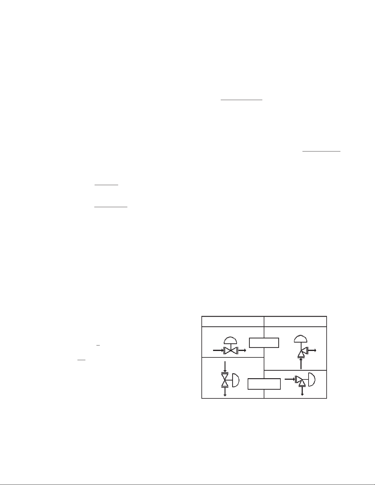
2. Valve body must be installed in a horizontal or
vertical plane where the outlet connection fl ow
direction is down wards or horizontal. Failure
to comply will cause the self-draining of the
internal passages to be nullifi ed, allowing CIP
clean ing/fl ushing fl uids to be ponded. See
Figure 1.
SECTION IV
Straight Pattern
HORIZONTAL
OUTLET
VERTICAL DOWN
OUTLET
Angle Pattern
Figure 1: Installation Orientation
2
IOM-SCV-S
Page 3

SECTION V
V. MAINTENANCE
A. General:
WARNING
SYSTEM UNDER PRESSURE. Prior to per form ing any
body disassembly or removal for maintenance, in spec tion or cleaning, isolate the valve body from the system
and relieve all pressure. Failure to do so could result
in personal injury.
1. Maintenance procedures hereinafter are
based upon removal of the control valve unit
from the piping system where installed.
2. Owner should refer to their pro ce dures for re mov al, handling and cleaning of non-re us able
parts, i.e. gaskets, diaphragm, etc.
3. Valves supplied from the factory use a light
coat of Emhart Bostic White Food Grade
"NEVER_SEEZ" or equivalent on seals and
threads.
4. Reference Figures 2 through 6 for iden ti fi ca-
tion of item numbers.
5. All item numbers with respect to body as sem bly (BA) will be in parenthesis and not
un der scored; i.e. (1). All item numbers with
respect to the actuator assembly (AA) and
positioner will be in parenthesis and un der scored; i.e. (3). Reference with respect to
the po si tion er is in double parentheses; i.e.
((AP)).
6. Special care must be exhibited when ro-
tat ing the stem (3,10) of the valve to not
mar that portion of the surface of the stem
where it contacts with the seal o-rings (9).
To rotate the stem (3,10), use the jam nuts (17)
or grasp stem with soft-jawed pliers. NOTE:
When using the jam nuts to rotate the stem,
use the upper jam nut to rotate the stem CW,
and the lower jam nut to rotate the stem CCW,
when viewed from above valve stem.
7. Hereafter, whenever text has the fol low ing
no ta tion, “(Note PA.)”, the fol low ing text is
to be ap plied;
8. Hereafter, whenever text has the fol low ing
no ta tion, “(Note RP.)”, the fol low ing text is to
be applied:
“For ATO-FC reverse action units, re lease
all tem po rary air pressure.
B. Separation of Body/Actuator with Std Threaded
Stem:
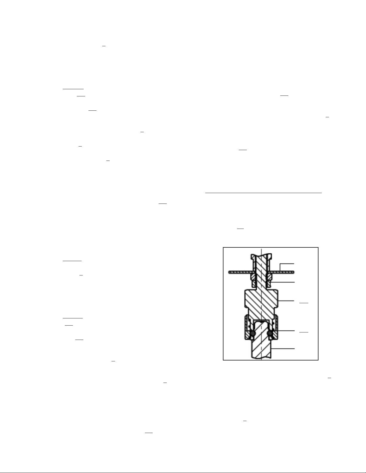
NOTE: For units with Opt-68 Quick Dis con nect
Stem proceed to Section V.C. See Fig. 2.
1. Secure body (1) into a vise with the actuator
as sem bly (AA) in the upwards orientation.
Place matchmarks between the yoke (3),
®
bonnet (2), Tri-Clamp
(4), and body (1) to
assist in fi nal ori en ta tion when the body is
dis as sem bled and/or the actuator removed.
2. Using an overhead hoist, rig the actuator as sem bly (AA) for a vertical lift. Remove slack
from rigging.
3. (Note PA.) Rotate yoke nut (8), CCW (viewed
from above) ap prox i mate ly 2 rev o lu tions. Secure the ac tu a tor stem (6). Loose jam nuts
(17) by rotating CW one-at-a-time to base of
stem (3) threads.
4. Fully loosen any accessory devices that are
connected to the stem (3,6) such as accessory
plate ((AP)) for positioner. (Note RP.)
NOTE: To fully disengage actuator stem (6)
from the stem (3) is a two-step pro ce dure.
Be aware of the valve’s stroke length as in di cat ed on the name plate (40) before be gin ning
dis en gage ment. During the dis en gage ment,
mea sure the dis tance ex tend ed, and stay at
least 1/8" (3 mm) away from the full stroke
length. Count and record the number of
rev o lu tions for each step in the box below:
No. of revolutions to disengage plug/stem from
actuator stem:
Step A. Step B.
TOTAL:
5. For ATO-FC Reverse Action Units:
IOM-SCV-S
“For ATO-FC reverse action units, connect
a temporary air source to the actuator and
pres sur ize to a level suf fi cient to initiate
travel to ap prox i mate ly mid-stroke.
a. (Note PA.)
b. Step A. Rotate stem (3) CW (viewed from
above) to disengage the ac tu a tor stem (6)
3
Page 4
from the plug/stem (3), while holding the
actuator stem (6). Record the num ber of
plug/stem rev o lu tions for Step A above.
When the dis en gage ment reach es about
50% of full stroke trav el Step A is com plet ed. (Note RP).
cau tious ly to prevent dan gling parts –
indicating washer (16), ac ces so ry plate
((AP)), yoke nut (8) - from falling.
C. Separation of Body/Actuator with Opt-68 Quick
Disconnect Stem:
c. Step B. Support the actuator as sem-
bly (AA) from above. Fully loosen
yoke nut (8). Lift the actuator as sem bly (AA) up wards ap prox i mate ly
1/4"-3/8" (6-8 mm). Again, rotate plug/
stem (3) CW (viewed from above) to
dis en gage the ac tu a tor stem (6) from the
plug/stem (3) while holding the ac tu a tor
stem (6). Record the number of plug/stem
rev o lu tions for Step B above. This should
allow the stems (6) (3) to fully dis en gage.
NOTE: Take notice of the parts “dan gling
loosely” about the stem (3), the order of their
lo ca tion and their proper orientation.
d. Fully raise the actuator assembly (AA)
from the valve body assembly (BA).
Re move cautiously to prevent dan gling
parts - indicating washer (16), ac ces so ry
plate ((AP)), yoke nut (8) - from fall ing.
6. For ATC-FO Direct Action Units:
a. Step A. Rotate plug/stem (3) CW (viewed
from above) to disengage the ac tu a tor
stem (6). Do not rotate the plug (3) into
the seat (11). Record the number of
stem (3) rev o lu tions for Step A. When
the dis en gage ment reach es about 75%
of full stroke travel, Step A. is com plet ed.
1. Place body assembly (BA) into a vise with
the actuator as sem bly (AA) in the upwards
position.
2. Place matchmarks between the yoke (3),
®
bonnet (2), Tri-Clamp
(4), and body (1) to
assist during re-assembly.
3. Using an overhead hoist, rig the actuator as sem bly (AA) for a vertical lift. Remove slack
from rigging.
4. Rotate yoke nut (8), (turning CCW viewed
from above actuator) until fully dis-engaged.
For ATO-FC (Reverse) Action Units Only:
Connect a temporary air supply hose that has an
ad just able airset with gauge to the ac tu a tor inlet
to allow pres sur iza tion. Pressurize the actuator
to upper limit of the bench range specifi ed on the
name plate (40). (NOTE: Pressure will lift the plug/
stem (10) away from the body's (1) integral seat
until the plug is 100% open.).
16
17
42a
b. Step B. Support the actuator as sem bly
(AA) from above. Fully loosen yoke nut
(8) and remove. Lift the actuator as sem bly (AA) upwards ap prox i
mate ly 1/4" 3/8" (6-8 mm). Again, rotate plug/stem
(3) CW (viewed from above) to dis en gage
42b
10
the ac tu a tor stem (6) from the plug/stem,
while holding the actuator stem. Record
the number of plug/stem rev o lu tions for
Step B. This should allow the stems (6)
(3) to fully disengage.
5. The valve stem (10)-to-actuator stem (6)
Figure 2: Opt.-68 Quick Disconnect
assembly is a quick disconnect joint. Grasp
stem (10) between thumb and fore fi n ger of one
hand. Grasp the lower collar (42b) between
NOTE: Take notice of the parts “dangling
loosely” about the stem (3), the order of their
lo ca tion and their proper orientation.
the thumb and fore fi n ger of the other hand.
Slide/push lower collar (42b) upwards. Stems
(10) and (6) should uncouple and separate.
NOTE: Take care to not “drop” the plug/stem
c. Fully raise actuator assembly (AA) from
the valve body assembly (BA). Re move
4
(10) down wards into the body’s (1) integral seat;
lower slow ly to this po si tion.
IOM-SCV-S
Page 5

6. Release temporary air pressure.
7. Lift actuator assembly (AA) up wards until able
to swing out of the way and set down onto
work surface.
D. Body Disassembly:
1. Remove actuator assembly (AA) per Sec tion
V.B.1-6 or V.C.1-7.
Place new seat disc on threaded end of
plug and re-install in nut. Place stem on
threaded end of plug and secure tight.
Special care must be exhibited when
ro tat ing the stem to not mar that portion of the surface of the stem where
it contacts with the seal o-rings (9).
Inspect the body (1) seating surface. If
seating surface shows wear, re place the
body.
2. Remove clamp nuts (4.3), wash ers (4.4), bolts
(4.2), and clamps (4.1).
4.2
4.1
Figure 3 : Clamp Orientation
4.3
4.4
4.1
3. Hold stem (3,10) securely, pull up wards, lifting
bonnet (2) away from body (1).
4. Slide bonnet (2) up over end of plug/stem
(3,10) and set both aside.
5. Remove gasket (7) from body (1) -to-bonnet
(2) joint. Discard gasket (7).
E. Trim Inspection and Replacement:
1. Inspect body (1), bonnet (2) and stem plug (3)
or seat disc (13) for wear. If seating surfaces
show signs of wear, proceed as follows:
2. Pick up bonnet (2) and using a thin-edged
tool, remove both upper and lower stem seal
rings (9) and discard used seal rings.
3. Clean all parts per owner’s pro ce dures. A fi nal
rinse with ultra-clean water is rec om mend ed.
CAUTION
Owner’s cleaning solution must be com pat i ble with control
valve’s trim ma te ri als.
F. Body Reassembly:
1. Place body (1) into vise ori ent ed for vertical
plug/stem position.
2. Place new gasket (7) onto body (1) fl ange.
3. Lubricate O.D. of stem seals (9) and carefully
insert new spring-as sist ed stem seal rings (9)
back into the bon net’s (2) grooves. "Open"
face of both seal rings oriented downwards
towards the plug head. (Detail "A")
CAUTION
Do not use any sharp-edged tool to install the lower and
upper stem seal rings (9).
IOM-SCV-S
a. For metal seated plug construction, place
lap ping com pound on seat ing sur fac es,
re as sem ble body as sem bly (BA), and
hand-lap the plug/stem (3) to re move
minor seat wear. If hand-lapped, both
the body (1) and plug/stem (3) head will
re quire care ful me chan i cal pol ish ing and
me chan i cal buffi ng; chemical electro-
pol ish ing may be required.
b. For composition seated con struc tion,
secure stem/plug assembly (10) in a
soft-jawed vise (plug end down) using the
fl ats on the nut (12). Rotate stem CCW to
remove. Insert fl at blade screwdriver into
the slot in the end of the plug and rotate
CW to remove plug (15) and seat disc(13).
4. Lubricate I.D. of stem seals (9). Insert the upper end of the stem (3,10) through the bon net
(2) and thru both stem seal rings (9).
5. Set bonnet (2) with inserted plug/stem onto the
fl ange of the body (1). Lower plug/stem until
it touch es the body seat. Press down fi rmly
on the stem (3, 10) up per end.
6. Re-position clamps (4.1), bolts (4.2), washers (4.4), and nuts (4.3) around the body (1)
to-bonnet (2) joint. Rotate clamp nuts (4.3)
a few revolutions in an alternating pattern
to hold clamp assembly Align matchmarks.
Position both hands around the outside of the
Tri-Clamp®, push the clamp to wards the valve’s
center. Ensure proper alignment of body (1)
5
Page 6

with bonnet (2) by checking OD of fl anges.
Finger-tighten clamp nuts (4.3). NOTE: Gap
be tween clamp (4.1) halves should be equal
in size. See Figure 3.
7. Rotate upper jam nut (17) up underneath
indicating washer (16) or accessory plate
((AP)) and secure tight. Rotate lower jam nut
up underneath upper jam nut - snug.
7. Wrench-tighten each clamp nut (4.3) in al ter nate one-half rev o lu tion increments. Final
tight en clamp bolting (4.2)(4.3) to a 20 Ft-lbs
(27 N-m) torque value.
8. Reinstall actuator assembly (AA) to body assembly (BA) per Section V.G. or V.H.
G. Mounting - Actuator to Body Std Threaded
Stem:
1. Place body assembly (BA) into a vise securely
with the stem (3, 10) directed upwards.
2. Install jam nuts (17) on stem (3), rotate CW
down to base of threads and secure together
tight.
3. Using an overhead hoist, rig and lift actuator
assembly (AA) above body assembly (BA).
Lower actuator as sem bly (AA) down and over
stem (3), so the upper end of the stem passes
thru lower opening of the yoke (3) and thru
yoke nut (8).
4. Reposition indicating washer (16) or accessory
plate ((AP)) over end of stem.
For ATO-FC Reverse Action Units:
Connect a temporary air supply hose that has
an ad just able airset with gauge to the actuator
and pressurize the actuator to upper limit of the
bench range specifi ed on the name plate (40).
For ATC-FO Direct Action Units:
Not necessary to connect temporary air supply.
5. Continue to lower actuator assembly until
it rest on the bonnet (2). Align actuator assembly (AA) and body assembly (BA) with
matchmarks of V.B.1 pre vi ous. Place yoke
nut (8) onto bonnet threads and hand tighten.
6. With hand, grasp and lift plug/stem (3) up to
connect with ac tu a tor stem (6). Rotate valve
stem CCW (viewed from above) to en gage w/
ac tu a tor stem (6). Use the total number of
revs en gage ment recorded in Step V.B.5. or
Step V.B.6. as the guide to control engagement
of the stems (6) (3.1). NOTE: For ATO-FC
Action may need to slowly decrease actuator
pressure to allow stem and collar to engage.
8. Tighten yoke nut (8) to 85 ft-# (115 N-M).
For ATO-FC (Reverse) Action Units Only: Release all pressure from the actuator.
H. Mounting - Actuator to Body Opt-68 QDS:
1. Place body into a vise securely with the plug/
stem (10) directed upwards.
2. Using an overhead hoist, rig and lift actuator
assembly (AA) above body assembly (BA).
Lower actuator as sem bly (AA) down and over
valve stem (10), so the upper end of the valve
stem passes thru lower opening of the yoke
(3) and thru yoke nut (8).
For ATO-FC Reverse Action Units:
Connect a temporary air supply hose that has
an ad just able airset with gauge to the actuator
and pressurize the actuator to upper limit of the
bench range specifi ed on the name plate (40).
For ATC-FO Direct Action Units:
Not necessary to connet temporary air supply.
3. Continue to lower actuator assembly until
it rest on the bonnet (2). Align actuator assembly (AA) and body assembly (BA) with
matchmarks of V.B.1 pre vi ous. Place yoke
nut (8) onto bonnet threads and hand tighten.
4. Grasp stem (10) between thumb and forefi n-
ger of one hand. Grasp collar (42b) be tween
thumb and forefi nger of the oth er hand. Lift
stem up and into the opening of the lower collar (42b). Slide/push the collar (42b) upwards
while si mul ta neous ly lifting the plug/stem
end into the quick disconnect (42) as sem bly.
A “click” will be felt when the engagement is
prop er; release the collar (42b). The lower
lips of the collar (42b) and the ac tu a tor stem
(6) assembly should align. Re lease the plug/
stem (10) to en sure en gage ment. NOTE: For
ATO-FC Action may need to slowly decrease
actuator pressure to allow stem and collar to
engage.
5. Tighten yoke nut (8) to 85 ft-# (115 N-M)
For ATO-FC (Reverse) Action Units Only: Release all pressure from the actuator.
6
IOM-SCV-S
Page 7

VI. CALIBRATION
A. General:
1. This section only covers cal i bra tion of the
control valve with Actuator Model C27-C53.
2. Positioner, if in stalled, requires ref er ence to
the spe cifi c positioner mod el IOM for prop er
cal i bra tion pro ce dure.
3. All indicated items numbers that are with
re spect to IOM-C27-C53 will be in pa ren the sis and un der scored; i.e. (20); those that
reference the po si tion er IOM will be in double
paranthesis; i.e. ((AP)). All item numbers that
are with respect to this IOM-SCV-S are not
un der scored; i.e. (3).
B. Procedure - Reverse Action, ATO-FC:
1. Reference the name plate (40) at tached to
the actuator yoke (3). De ter mine the bench
set ting of the installed range springs (10) from
the name plate (40).
2. Connect a temporary air supply with an in-line
ad just able airset reg u la tor and gauge to the
lower actuator con nec tion. DO NOT LOAD
with any air pressure at this point.
3. To determine when stem/plug (3,10) begins
to lift out of the seat, touch the stem with one
fi nger. (Stem will begin to move when actuator pressure exceeds the spring load.)
4. Slowly pressurize the ac tu a tor to a pres sure
equal to the lower pres sure level of the bench
setting; i.e. for 5-15 psig (.34–1.03 Barg)
range, set pressure at 5 psig (.34 Barg). Take
note of pressure reading when the stem fi rst
begins to move.
5. If the loading pressure for the start of stem
movement is below the lower end of the
desired bench setting, then the com bined
stem (3,10 & 6) length is too short.
For Std Threaded Stem:
a. Rotate both jam nuts (17) down to base of
threads on stem (3) and tighten together.
b. Increase pressure in the actuator to
approximately mid range of the bench
setting.
c. Rotate upper jam nut CW to increase the
combined stem length. DO NOT allow
actuator stem (6) to rotate in the actuator.
SECTION VI
d. Rotate upper jam nut CCW to hold indi-
cating washer (16) up against stem (6).
e. Release all pressure from the actuator and
repeat Step 4 previous.
For Opt-68 QDS Stem:
a. Rotate jam nuts (17) down to base of
threads on upper collar (42a).
b. Increase pressure in actuator to approxi-
mately mid range of the bench setting.
c. Rotate upper collar (42a) CCW to increase
the combined stem length. DO NOT allow
actuator stem (6) to rotate in the actuator.
d. Rotate upper jam nut CW to hold indicator
washer (16) up against stem (6).
e. Release all pressure from the actuator
and repeat Step 4 previous.
6. If the loading pressure for the start of stem
movement is above the lower end of the
desired bench setting, then the com bined
stem (10, 6) length is too long.
For Std Threaded Stem:
a. Rotate both jam nuts (17) down to base of
threads on stem (3) and tighten together.
b. Increase pressure in the actuator to ap-
proximately mid range of the bench set.
c. Rotate lower jam nut CCW to shorten the
combined stem length. DO NOT allow
actuator stem (6) to rotate in the actuator.
d. Rotate upper jam nut CCW to hold indi-
cating washer (16) up against stem (6).
e. Release all pressure from the actuator
and repeat Step 4 previous.
For Opt-68 QDS Stem:
a. Rotate jam nuts (17) down to base of
threads on upper collar (42a).
b. Increase pressure in actuator to approxi-
mately mid range of the bench setting.
c. Rotate upper collar (42a) CW to shorten
the combined stem length. DO NOT allow
actuator stem (6) to rotate in the actuator.
d. Rotate upper jam nut CW to hold indicator
washer (16) up against stem (6).
e. Release all pressure from the actuator
and repeat Step 4 previous.
7. After the opening set point pressure has been
established, rotate lower jam nut (17) CW up
tight under the upper jam nut.
8. Release all pressure from the actuator.
9. Observe the location of the in di ca ting washer
IOM-SCV-S
7
Page 8

(16) to the "C" mark on the in di ca tor plate
(23), mak ing sure to use the “top edge” of the
in di ca ting washer (16) as the ref er ence point.
Adjust indicator plate as needed.
10. Slowly increase the pressure in the actuator
until the indicating washer (16) is in alignment
with the "O" mark on the indicator plate.
11. To limit the up travel at the desired stroke
length, rotate the travel stop nut (52) CW and
secure to bottom of attachment hub (4).
NOTE: Secure the actuator stem (6) by the
fl ats when rotating the travel stop nut.
NOTE: "Stroke" length is indicated on the
nameplate (40), and is the distance between
the "C" and "O" marks of the indicator plate
(23).
NOTE: The proper calibration of the actuator
/ valve unit will occur when at the lower pressure level of bench setting, the valve plug (3)
will just begin to travel from the "C" position.
At the upper level of the bench setting, the
actuator pressure should be within ±8% of
the upper bench range for the desired stroke
length.
12. Release all pressure from actuator.
C. Procedure - Direct Action, ATC-FO:
1. Reference the nameplate (40) attached to
the actuator yoke (3). Determine the bench
set ting of the installed range springs (10) from
the nameplate (40).
2. Connect a temporary air supply with an in-line
ad just able airset regulator and gauge to the
upper actuator con nec tion. DO NOT LOAD
with any air pressure at this point.
3. To determine when stem/plug (3) makes
contact with the seat and travel stops, touch
the stem with one fi nger. (Stem movement
will stop when the plug engages the seat.)
4. Slowly pressurize the ac tu a tor to a pres sure
equal to the upper pres sure lev el of the benchsetting; i.e. for a 5-15 psig (.34 -1.0 Barg)
range, set pressure at 15 psig (1.0 Barg).
Take note of the pressure reading when stem
travel actually stops.
5. If the loading pressure, when stem movement
stops, is below the upper end of the desired
bench setting, then the com bined stem (3,10,
& 6) length is too long.
For Std Threaded Stem:
a. Rotate both jam nuts (17) down to base of
threads on stem (3) and tighten together.
b. Decrease pressure in the actuator to
approximately mid range of the bench
setting.
c. Rotate lower jam nut CCW to shorten the
combined stem length. DO NOT allow
actuator stem (6) to rotate in the actuator.
d. Rotate upper jam nut CW to hold indicat-
ing washer (16) up against stem (6).
e. Release all pressure from the actuator
and repeat Step 4 previous.
For Opt-68 QDS Stem:
a. Rotate jam nuts (17) down to base of
threads on upper coupling (42a).
b. Decrease pressure in the actuator to
approximately mid range of the bench
setting.
c. Rotate upper coupling (42a) CW to shorten
the combined stem length. DO NOT allow
actuator stem (6) to rotate in the actuator.
d. Rotate upper jam nut CW to hold indicator
washer (16) up against stem (6).
e. Release all pressure from the actuator
and repeat Step 4 previous.
6. If the loading pressure, when stem movement
stops, is above the upper end of the desired
bench setting, then the com bined stem (3,10
& 6) length is too short.
For Std Threaded Stem:
a. Rotate both jam nuts (17) down to base of
threads on stem (3) and tighten together.
b. Decrease pressure in the actuator to
approximately mid range of the bench
setting.
c. Rotate upper jam nut CW to increase the
combined stem length. DO NOT allow
actuator stem (6) to rotate in the actuator.
d. Rotate upper jam nut CCW to hold indicat-
ing washer (16) up against stem (6).
e. Release all pressure from the actuator
and repeat Step 4 previous.
For Opt-68 QDS Stem:
a. Rotate jam nuts (17) down to base of
threads on upper coupling (42a).
b. Decrease pressure in the actuator to
approximately mid range of the bench
setting.
c. Rotate upper coupling (42a) CCW to
increase the combined stem length. DO
NOT allow actuator stem (6) to rotate in
the actuator.
8
IOM-SCV-S
Page 9

d. Rotate upper jam nut CW to hold indica-
tor washer (16) up against stem (6).
e. Release all pressure from the actuator
and repeat Step 4 previous.
7. After the closed- set point pressure has been
established, rotate lower jam nut (17) CW
up tight under the upper jam nut.
8. Increase pressure in the actuator to the upper pressure level of the bench setting.
9. Observe the location of the in di ca ting washer
(16) to the "C" mark on the in di ca tor plate
(23), mak ing sure to use the “top edge” of
the in di ca ting washer (16) as the ref er ence
point. Adjust indicator plate as needed.
10. Slowly decrease air pressure in actuator until
indicating washer (16) is in alignment with
the “O” mark on the indicator plate (23)
11. To limit the up travel at the desired stroke
length, rotate the travel stop nut (52) CW and
secure to bottom of attachment hub (4).
NOTE: Secure the actuator stem (6) by the
fl ats when rotating the travel stop nut.
NOTE: "Stroke" length is indicated on the
nameplate (40), and is the distance between
the "C" and "O" marks of the indicator plate
(23).
NOTE: The proper calibration of the actuator
/ valve unit will occur when at the upper pressure level of bench setting, the valve plug (3)
will be in the "C" position. At the lower level
of the bench setting, the actuator pressure
should be within ±8% of the lower bench
range for the designed stroke length.
12. Release all pressure from actuator.
IOM-SCV-S
9
Page 10

SEC TION VII
VII. TROUBLE SHOOTING GUIDE
1. Unit can not pass enough fl ow.
Possible Cause Remedy
A. Sizing data not correct; valve undersized. A1. Check actual pressures, temperature, and fl ow rates against
the variables used for sizing.
Recalculate Cv Required.
A2. Replace unit with larger body size.
B. Obstruction at inlet. B. Remove valve and inspect line for blockage.
C. Insuffi cient valve travel. C1. Verify full travel.
C2. Verify correct IAS pressure.
2. Unit can not control steadily at low fl ow rates.
Possible Cause Remedy
A. Sizing data not correct; valve oversized. A1. Check actual pressures, temperature and fl ow rates against
the variables used.
A2. Replace full port body with reduced port body.
B. Obstruction at inlet. B. Remove valve from line and inspect for something
causing blockage.
C. Too short of “stroke”. C. Remove unit and calibrate.
D. Excess pressure drop. D1. Check actuator bench setting; re-calibrate as required.
D2. Check design pressures against actual pressures. Replace
“low” bench set range springs with higher bench set
range springs.
E. Insuffi cient IAS pressure. E. Provide required level of IAS pressure.
F. Incorrect fl ow direction. F. Verify fl ow with arrow cast on body; FTO
3. Valve body leaking at clamped end connection joints.
Possible Cause Remedy
A. Excess pressure levels. A. Check actual pressures against those indicated in Technical
Bulletin. Reduce pressures as necessary.
B. Loose clamp. B. Remove valve from service. Disassemble and clean.
Reassemble and properly tighten all clamps at reinstallation.
C. Excessive piping stress. C. Place hanger on control valve unit.
D. Improper pipe alignment. D. Re-do piping properly.
4. Fluid leakage at bonnet or at upper stem seal ring.
Possible Cause Remedy
A. Gasket failure. A1. Remove body, disassemble, remove old gasket Install new
gasket,new stem seals, reassemble and reinstall.
A2. Seal ring failure.
B. Overheating B. Ensure that max. operating temperature of
366°F (186°C) is not exceeded.)
C. Stem seal failure C1. Worn stem seals. Replace seals and gasket.
C2. Pitted stem, worn stem. Replace plug/stem, seals and gasket.
5. Inadequate valve shutoff.
Possible Cause Remedy
A. Permanent "tracks" where seating occurs. A1. Relap body seat and plug (metal seat).
A2. Replace body and plug or comp. seat disc.
B. Excess valve pressure drop. B. Reduce valve's shutoff pressure drop.
C. Insuffi cient IAS pressure. C. Provide required level of IAS pressure.
D. Obstruction at seat. D. Remove body and inspect for obstruction.
E. Improper calibration. E. Recalibrate positioner and valve stroke.
F. Improper actuator bench set range. F. Disassemble actuator and change to stiffer range springs.
Reinstall and increase IAS to proper level.
10
IOM-SCV-S
Page 11

6. Unit will not operate.
Possible Cause Remedy
A. IAS is “off”. A. Turn “on” the IAS and set at proper level.
B. Faulty positioner. B. Service positioner or replace.
C. Improper positioner action. C. Switch positioner to proper action unit.
D. Actuator has a leak. D. Manually load actuator to test for pressure integrity.
Replace diaphragm and O-ring if either is leaking.
7. Instability.
Possible Cause Remedy
A. Insuffi cient dampening. A. Recalibrate and set dampening adjustment of positioner.
B. Flow conditions. B. Reduce disturbances in fl uid fl ow stream.
SECTION VIII
VIII. ORDERING INFORMATION
NEW REPLACEMENT UNIT vs PARTS "KIT" FOR FIELD REPAIR
To obtain a quotation or place an order, please retrieve the Serial Number and Product Code that was stamped on
the metal name plate and attached to the unit. This information can also be found on the Bill of Material ("BOM"),
a parts list that was provided when unit was originally shipped. (Serial Number typically 6 digits). Product Code
typical format as follows: (last digit is alpha character that refl ects revision level for the product).
–
NEW REPLACEMENT UNIT:
Contact your local Cashco, Inc., Sales Rep re sen ta tive with the Serial Number and Product code.
With this information they can provide a quotation
for a new unit including a complete description,
price and availability.
CAUTION
Do not attempt to alter the original construction of any
unit without assistance and approval from the factory. All
purposed changes will require a new name plate with appropriate ratings and new product code to accommodate
the recommended part(s) changes.
–
7
PARTS "KIT" for FIELD REPAIR:
Contact your local Cashco, Inc., Sales Rep re sen ta tive with the Serial Number and Product code.
Identify the parts and the quantity required to repair
the unit from the "BOM" sheet that was provided
when unit was originally shipped.
NOTE: Those part numbers that have a quantity indicated
under "Spare Parts" in column "A” refl ect minimum
parts required for inspection and rebuild, - "Soft
Goods Kit". Those in column “B” include minimum
trim replacement parts needed plus those "Soft
Goods" parts from column "A".
If the "BOM" is not available, refer to the crosssectional drawings included in this manual for part
identifi cation and selection.
A Local Sales Representative will provide quotation
for appropriate Kit Number, Price and Availability.
The contents of this publication are presented for informational purposes only, and while every effort has been made to ensure their accuracy, they are not to be construed as warranties or guarantees, express or implied, regarding the products or services described herein or their use or applicability. We reserve the right to modify
or improve the designs or specifi cations of such product at any time without notice.
Cashco, Inc. does not assume responsibility for the selection, use or maintenance of any product. Responsibility for proper selection, use and maintenance of any
Cashco, Inc. product remains solely with the purchaser.
IOM-SCV-S
11
Page 12

Detail A
OPT-68
FIGURE 4:
Straight-Globe Body Assembly (BA),
Metal Seat
REPLACEMENT
ITEM NO. DESCRIPTION PARTS
1 Body
2 Bonnet
3 Stem/Metal Plug *
4 “Tri-Clover” Clamp
7 Gasket *
8 Yoke Nut
9 Seal Rings (2 req'd.) *
10 Stem/Composition Seat *
11 Gasket *
12 Seat Nut *
13 Seat Disc *
14 Pin *
15 Plug *
16 Indicating Washer
17 Stem Jam Nuts
ITEMS NOT SHOWN
Figure 6:
Composition seat with
OPT-68 Quick Disconnect
ITEM NO. DESCRIPTION
5 Flow Arrow Tag
6 Drive Screw
42 See Figure 3
Cashco, Inc.
P.O. Box 6
Ellsworth, KS 67439-0006
PH (785) 472-4461
Fax. # (785) 472-3539
www.cashco.com
email: sales@cashco.com
Printed in U.S.A. SCV-S-IOM
Cashco GmbH
Handwerkerstrasse 15
15366 Hoppegarten, Germany
PH +49 3342 4243135
Fax. No. +49 3342 4243136
www.cashco.com
Email: germany@cashco.com
12
Cashco do Brasil, Ltda.
Al.Venus, 340
Indaiatuba - Sao Paulo, Brazil
PH +55 11 99677 7177
Fax. No.
www.cashco.com
Email: brazil@cashco.com
FIGURE 5:
Angle-Globe Body Assembly (BA),
Metal Seat
IOM-SCV-S
 Loading...