

Page 1
INSTALLATION, OPERATION & MAINTENANCE MANUAL (IOM)
IOM-POSR-1
12-13
MODEL POSR-1
PILOT OPERATED PRESSURE RE DUC ING REGULATOR
SECTION I
I. DESCRIPTION AND SCOPE
The POSR-1 is a pilot operated pressure reducing reg u la tor used to control downstream (P2) pressure. The
POSR-1-20 is a pressure loaded (no pilot) option. Sizes are 1/2", 3/4" and 1" (DN15, 20 and 25). The unit is suitable
for steam service only. Refer to Technical Bulletin POSR-1-TB for design conditions and selection recommendations.
NOT RECOMMENDED FOR DEAD END SERVICE!
SECTION II
II. INSTALLATION
A. General:
WARNING
Do not dead end (no fl ow demand) downstream of POSR-1
if P1 - Inlet Pressure is greater than max i mum allowable
outlet design pressure.
Max. Allowable
Spring Range Out let Pressure
5-15 psig (0.34-1.03 Barg) 100 psig (6.9 Barg)
10-40 psig (0.69-2.8 Barg) 200 psig (13.8 Barg)
30-80 psig (2.1-5.5 Barg) 200 psig (13.8 Barg)
70-150 psig (4.8-10.3 Barg) 200 psig (13.8 Barg)
B. Piping the Valve:
1. An inlet block valve should always be in stalled.
2. If service application is continuous such that
shut down is not readily accomplished, it is
recommended that an inlet block valve, outlet
block valve, and a manual bypass valve be
installed.
3. Pipe unions are recommended for NPT
screwed in stal la tions to allow removal from
piping.
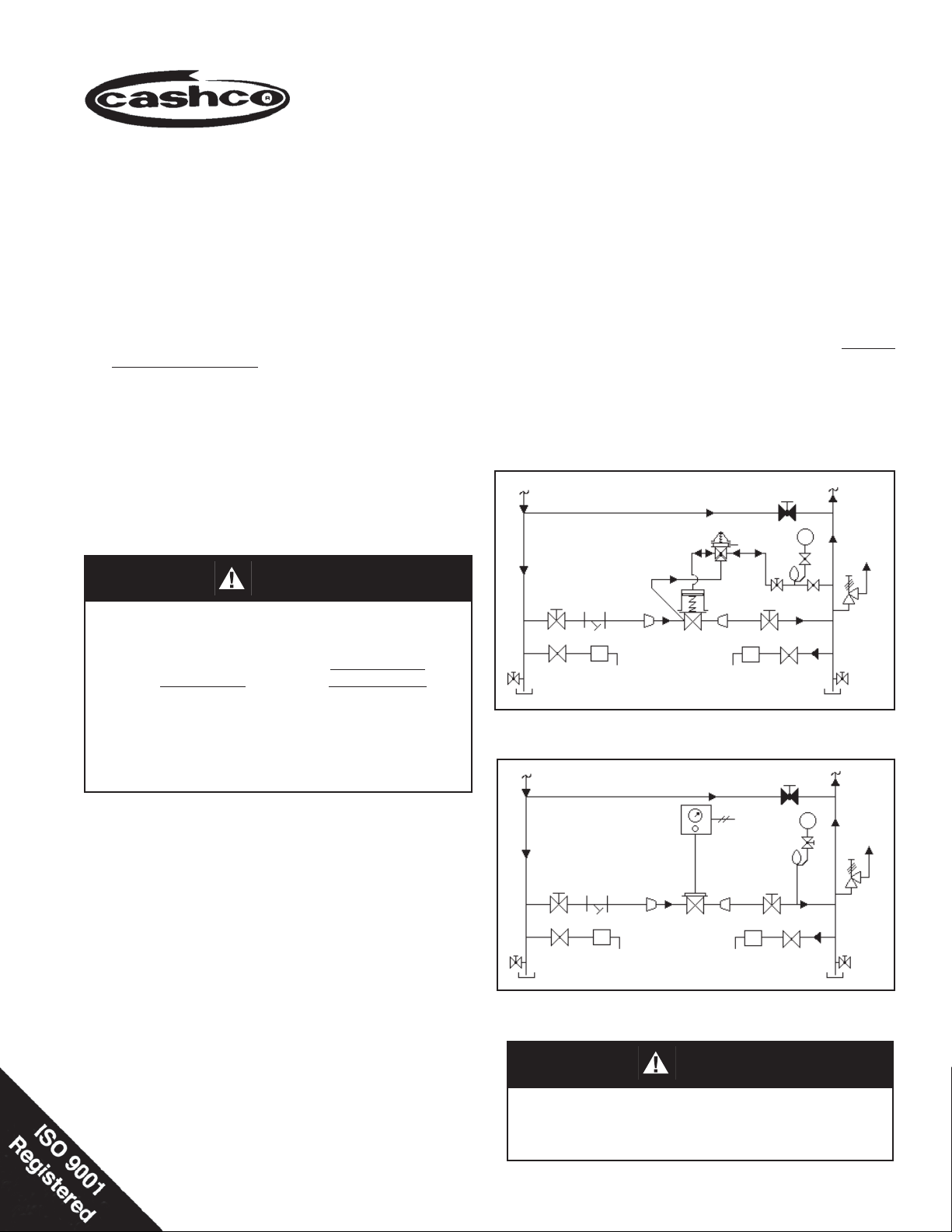
PI
Pilot
Valve
Main
TR
HP Cond.
Valve
MP/LP Cond.
TR
FIGURE 1
Recommended Piping Schematic for POSR-1
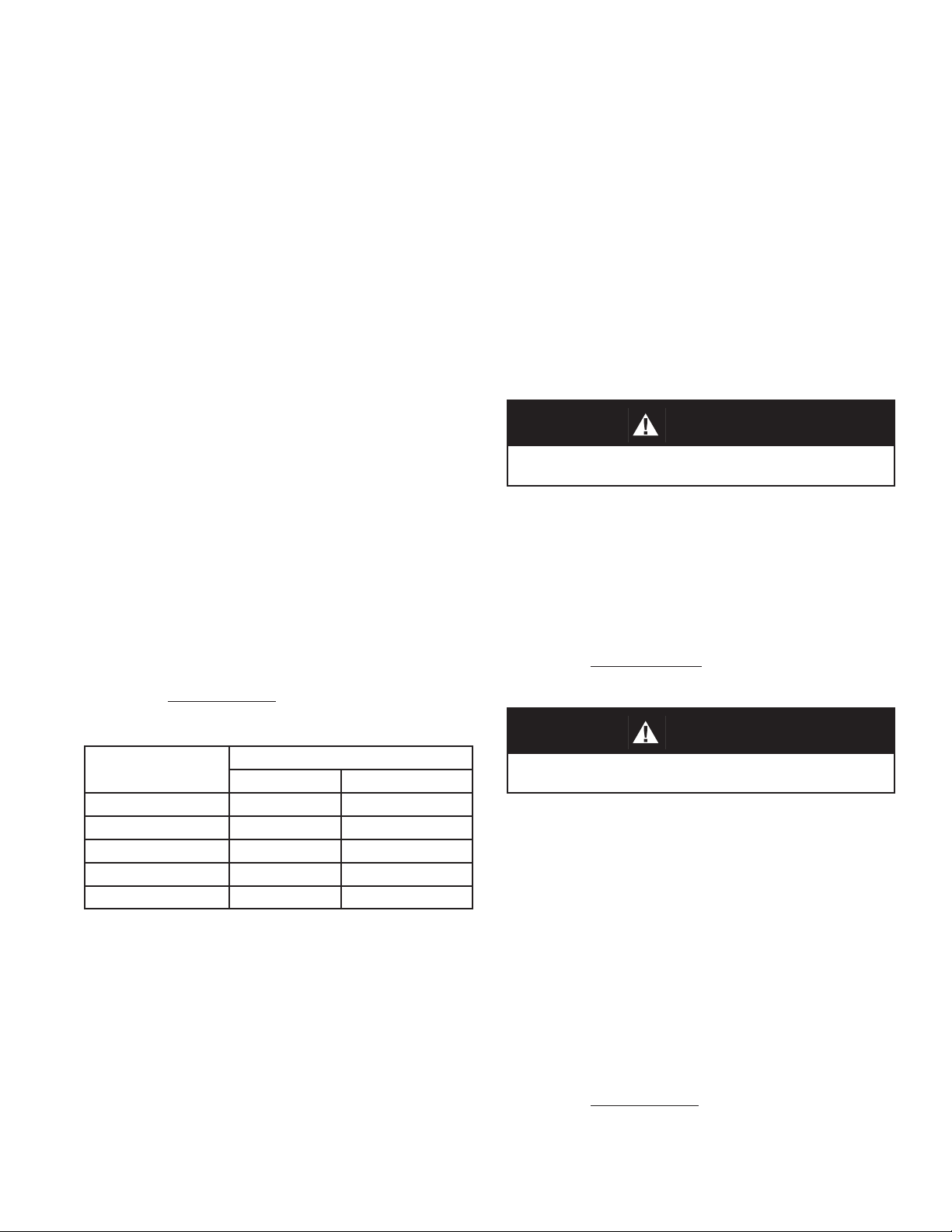
Airset or
Manual Loader
TR
HP Cond.
Main
Valve
Air
Supply
TR
MP/LP Cond.
PI
FIGURE 2
Recommended Piping Schematic for POSR-1-20
CAUTION
SRV
SRV
4. An outlet pressure gauge should be lo cat ed ap prox i mate ly ten pipe diameters down stream,
and within sight.
Installation of adequate overpressure pro tec tion is recommended to pro tect the reg u la tor from overpressure and
all down stream equip ment from damage in the event of
regulator failure.
Page 2

5. All installations should include a down stream
re lief device if the inlet pressure could ex ceed
the pressure rating of any downstream equip ment or the maximum allowable outlet pres sure
rating of the unit.
6. Clean the piping of all foreign material in clud ing
chips, welding scale, oil, grease and dirt before
installing the regulator. Strainers are recommended.
use 1/4" OD metal tubing for dis tanc es 4 ft
(1.2 m) or less, and 3/8" OD metal tubing (requires 1/4" x 3/8" tubing adapter) for distances
greater than 4 ft. (1.2 m). The sensing line
should always be sloped down ward so that
condensation will drain away from the pilot.
If regulator pipe line is ex pand ing to a larger
pipe line, always connect sens ing line to the
larger pipe line. NOTE: The POSR-1-20 does
not reguire a sensing line.
CAUTION
DO NOT HYDROSTATIC TEST THROUGH AN IN STALLED
UNIT, INCLUDING PILOT; ISOLATE BOTH PILOT AND MAIN
VALVE FROM TEST. The upper range spring pressure
level listed on the nameplate is the rec om mend ed “upper
op er a tive limit” for the sens ing diaphragm(s) in the pilot.
Higher pres sures could cause internal dam age. In addition,
note on the name plate that the Inlet and Outlet pressure
and tem per a ture rat ings are at different levels.
7. In placing thread sealant on pipe ends prior
to en gage ment, assure that excess material
is removed and not allowed to enter the reg u la tor upon start-up.
8. Flow Direction. Install so the fl ow direction
match es the arrow cast on the body.
9. The POSR-1 comes factory piped between
the pilot supply and pilot loading. Install an
external sensing line from the 1/4" NPT con nec tion opposite the factory piped pilot load ing
port to a point downstream at gauge location;
10. For best per for mance Cashco rec om mends
in stall ing regulator in a well drained horizontal
pipe, prop er ly trapped.
11. Recommended installation is with pilot valve
spring chamber vertical upwards. Orient such
that the spring chamber vent hole does not
collect rainwater or debris.
12. Regulators are not to be buried underground.
13. For insulated piping systems, rec om men da tion
is to not insulate regulator.
CAUTION
For welded installations, all internal trim parts, seals and
diaphragm(s) must be removed from reg u la tor body prior
to welding into pipeline. The heat of fusion welding will
dam age non-metallic parts if not re moved. NOTE: This
does not apply to units equipped with extended pipe
nip ples.
III. PRIN CI PLE OF OPERATION
A. General:
1. The POSR-1 pilot obtains its operating
medium from the main valve body inlet.
Down stream pressure (P2) registers on the
un der side of the main valve’s diaphragm and
the pilot valve’s diaphragm(s).
2. The loading pressure on the top side of the
main valve’s diaphragm is an intermediate
pressure higher than the downstream (P2)
pres sure by the sum of the pressures re quired
to overcome the main valve’s plug unbalance
force and the piston spring’s force.
3. The pilot has a bleed orifi ce that continu-
ously bleeds part of the loading medium
down stream. In op er a tion, the pilot valve’s
plug can fl ow more medium than is bleed-
SECTION III
ing down stream. This increases the loading
pres sure on the main valve’s plug and opens
valve. Partially closing the pilot valve’s plug
will reduce its fl ow to less than the amount
bleed ing downstream, and allows the loading
pressure on the main valve’s diaphragm to
de cay, allowing partial closing of the main
valve’s plug. This continues until steady-state
is de vel oped.
4. The pilot valve’s diaphragm(s) senses the
down stream (P2) pressure and compares
the force generated to the force developed
by the pilot’s range spring.
5. If, during operation, the downstream (P2) pres sure falls below the pilot valve’s setpoint, the
main valve’s diaphragm senses the reduced
pres sure on its underside and instantly moves
down, increasing the fl ow through the main
valve. At the same time, the pilot valve
IOM-POSR-12
Page 3
senses the reduced pressure and the pilot
valve’s plug increases its opening, elevating
the load ing pressure on the upper side of the
main valve’s diaphragm.The combined actions
increase fl ow enough to restore the down-
stream (P2) pressure to the setpoint.
6. If the downstream (P2) pressure rises above the
setpoint, the force developed by the in creased
pressure on the underside of the diaphragm
instantly moves it upward and partially closes
the main valve’s plug. Si mul ta neous ly, the
pilot valve’s plug partially clos es and al lows
SECTION IV
the loading pressure to decay through the
bleed orifi ce. The reduced load ing pres sure
on the upper side of the di a phragm closes
the main valve’s plug enough to re store the
down stream (P2) pressure to the setpoint.
7. Pressure setpoint is adjusted by changing
the com pres sion of the pilot’s range spring
by turning the adjusting screw either clockwise
(CW) or counter-clock wise (CCW). Turning the
adjusting screw clockwise (CW) will in crease
the downstream (P2) pressure. Turn ing the
adjusting screw counter-clockwise (CCW) will
decrease the down stream (P2) pressure.
IV. START-UP
CAUTION
A. General
1. Start with the block valves closed.
2. Ensure that the needle valve(s) on the sens ing
line is opened and downstream (P2) pres sure
is in di cat ing on pressure gauge.
3. Relax the pilot valve range spring by turning
the adjusting screw counter clockwise (CCW)
(viewed from above) a minimum of three (3)
full revolutions. This reduces the outlet (down stream) pressure setpoint.
For POSR-1-20 use manual loading valve to
set minimum loading pressure.
Outlet Pressure - P2
psig (Barg)
5 (0.34) 15 (1.03) 25 (1.7)
50 (3.45) 60 (4.1) 70 (4.8)
100 (6.90) 110 (7.6) 120 (8.3)
130 (8.97) 145 (10.0) 150 (10.3)
135 (9.31) 150 (10.3) – ( – )
Loading Pressure - P3, psig (Barg)
Minimum @ P1 Maximum
@ P
1
4. Slowly open the bypass valve to preheat the
system piping and to allow slow ex pan sion
of the piping. Assure proper steam trap op er a tion. Closely monitor outlet (down stream)
pressure via gauge to assure not over-pres sur iz ing. NOTE: If no bypass valve is in stalled,
extra caution should be used in start ing up a
cold system; i.e. do ev ery thing slowly.
5. Slowly open the outlet (downstream) block
valve until fully open. Slightly close the by pass
valve at same time.
IOM-POSR-1 3
Do not walk away and leave a bypassed reg u la tor unattended when on manual bypass!
6. Slowly open the inlet (upstream) block valve
ob serv ing the outlet (downstream) pres sure
gauge. De ter mine if the reg u la tor is fl owing.
If not, slightly close bypass valve, and then
slowly rotate the pilot valve adjusting screw
clock wise (CW) (viewed from above) until fl ow
begins.
For POSR-1-20 in crease load ing pres sure
until fl ow begins.
CAUTION
Do not exceed Maximum Loading Pressure limits for P2
set point.
7. Continue to alternate slow ly closing the
bypass valve and then slowly opening the inlet
(upstream) block valve, es pe cial ly when the
down stream piping sys tem isn’t pressurized.If
the outlet (downstream) pressure exceeds the
desired pressure, close the bypass valve until fully closed. If outlet pres sure still re mains
above desired level, rotate pilot’s ad just ing
screw CCW (viewed from above) in 1/2
rev o lu tion in cre ments until out let pres sure
reach es de sired level. If outlet pres sure is
below de sired level, ro tate pilot’s ad just ing
screw CW (viewed from above) until de sired
level is reached.
For POSR-1-20 adjust manual loading valve
to either increase or decrease loading pres sure until desired set point is reached. Do not
exceed limits.
Page 4

8. When fl ow is established steady enough that
the inlet (upstream) block valve is fully open,
begin to slowly close the bypass valve and
continue until fully closed.
9. Develop system fl ow to a level near its ex pect ed
normal rate, and reset the reg u la tor setpoint
by turning the pi lot valve ad just ing screw CW
SECTION V
(viewed from above) to in crease outlet pressure, or CCW to reduce outlet pres sure.
10. Reduce system fl ow to a minimum level and
observe setpoint. Outlet pressure will rise from
the set point of Step 9. There should be no
more than a 10% vari a tion in outlet pres sure
over the max i mum to min i mum fl ow range.
V. SHUTDOWN
A. General
1. On systems with a bypass valve, and where
system pressure is to be main tained as the
POSR-1 is shut down, slowly open the by pass
valve while closing the inlet (up stream) block
valve. Fully close the inlet (up stream) block
valve. (When on by pass, the sys tem pres sure
must be con stant ly ob served and man u al ly
reg u lat ed.) Close the outlet (down stream)
block valve. Close the nee dle valve on the
pilot valve’s sensing line.
SECTION Vl
VI. MAINTENANCE
CAUTION
SYSTEM UNDER PRESSURE. Prior to performing any
maintenance, isolate the regulator from the sys tem and
relieve all pressure. Failure to do so could result in personal injury.
CAUTION
Do not walk away and leave a bypassed reg u la tor unattended when on manual bypass!
2. If the regulator and system are to both be shut down, slowly close the inlet (up stream) block
valve. Close the out let (down stream) valve
only if reg u la tor re mov al is required. Close
the needle valve on the pilot valve’s sensing
line.
For POSR-1-20 close manual loading valve
and relieve loading pressure.
4. All indicated item numbers that are with
respect to the Pilot Valve will be in pa ren the sis and underscored, i.e. (14), (PV). All item
numbers that are with respect to the Main Valve
will NOT be underscored, i.e. (1), (MV).
5. Refer to Figures 3 and 4 for item num ber
callouts.
A. General:
1. Maintenance procedures hereinafter are based
upon removal of the regulator unit from the
pipeline where installed.
2. Owner should refer to owner’s procedures for
re mov al, handling, cleaning and dis pos al of
non-reuseable parts, i.e. gaskets, etc. Cash co
recommends not reusing any gas kets, but replacing with only new and fac to ry supplied
gaskets.
3. This regulator is supplied from the factory
using a gasket sealing aid, Federal Pro cess
Company, PLS 2, or equal. Such compatible
sealing aids may be utilized by the Owner, if
desired.
6. Most pilot-operated valve operation problems
center around the pilot valve (PV). Cashco
always rec om mends full maintenance on any
POSR-1 pilot valve (PV) once a POSR-1 is
removed from the pipeline.
B. Separation:
1. Observe position of pilot valve (PV) with
respect to main valve (MV) before dis as sem bling.
2. Place main valve body (1) into a vise, oriented
to allow rotation of pilot valve (PV) to geth er
with in ter con nect ing pipe nipple (19).
3. Remove loading tubing (21) at both end fi t-
tings (20) by rotating nut CCW (viewed from
tube-end).
IOM-POSR-14
Page 5

4. Place pipe wrench on interconnecting pipe
nipple (19) and rotate CCW (viewed from pilot valve (PV) end) to removal. Remove main
valve (MV) from vise and set aside.
NOTE: Pilot valves (PV) supplied with a 5–15
psig (0.34–1.03 Barg) range spring (15) have
only one di a phragm (12) sup plied; all other
spring ranges use two diaphragms (12).
5. Place pilot valve body (1) in vise. Remove pipe
nipple (19) by rotating CCW (viewed from end
of nipple) by pipe wrench.
6. Inspect the inside of the inter-connecting pipe
nipple (19) for corrosion, scaling, debris, or
fi lming. Prob lems here will be an in di ca tion
of improper condensate cor ro sion control
which can affect the overall operation of the
POSR-1. Install an upstream strainer if scale
or debris ap pears at this point.
7. Remove pilot valve (PV) from vise and set
aside.
C. Pilot Valve (PV):
WARNING
SPRING UNDER COMPRESSION. Pri or to re mov ing body
fl ange bolts, relieve spring com pres sion by back ing out
the adjusting screw. Failure to do so may result in fl ying
parts that could cause personal injury.
1. Securely install the pilot valve body (1) in
a vise with the spring chamber (2) directed
upwards.
7. Using a putty knife or similar tool, remove
diaphragm(s) (12) and di a phragm gasket
(13). In spect diaphragm(s) (12) for cracks or
de for ma tion. Radial creases and cracks in di cate over pres sure. Cracks circumferentially
in di cate high cycles, and may be due to nor mal
cy cling, or pulsing or chattering if pre ma ture.
Discard both diaphragm(s) (12) and gas ket
(13).
8. Using a 7/8" deep well socket, remove bel lows
(11) by rotating CCW (viewed from above).
Count and record the number of revolutions
required to remove the bellows (11) in the box
below:
Number of revolutions required to remove
bellows (11):________________.
Inspect the bellows (11) for a crack or joint
failure where leakage is occurring. Replace
bellows (11) if leaking.
9. Remove protruding stem extension (10).
10. Using a fl at, sharp-edged tool, clean body (1)
fl ange where diaphragm gasket (13) seals.
2. Loosen locknut (20) by rotating CCW (viewed
from above) ONLY two revolutions. Relax
range spring (15) by turning adjusting screw
(19) CCW (viewed from above) until removed
from spring chamber (2). Set ad just ing screw
(19) with locknut (20) aside.
3. Draw or embed a match mark between body
casting (1) and spring chamber casting (2)
along fl anged area.
4. Remove all diaphragm fl ange nuts (18) and
bolts (17).
5. Remove spring chamber (2) by lifting up wards.
Re move range spring (15) and spring button
(16).
6. Remove pressure plate(14). In spect to en sure
that the pressure plate (14) has not been
deformed by over pres sure by placing a
thin, straight bar or ruler across the side that
touch es the diaphragm (12). If the pressure
plate (14) does not touch the bar at its center
(i.e. a depression in center), the pres sure plate
(14) is deformed and must be replaced.
11. Using a wire gauge tool, clean the 0.068"
(1.73 mm) diameter bleed orifi ce located in
the body cavity (smaller of two holes) of any
fi lm or other buildup material that might be
restricting fl ow.
NOTE: Any signifi cant blockage of the bleed
orifi ce will downgrade a POSR-1's per for-
mance. If a buildup is form ing, attempt to determine the cause and remove the source.
12. Remove body (1) from vise and reorient with
body cap (9) on top; resecure body (1) in
vise.
13. Remove body cap (9) by rotating CCW (viewed
from above) with hex-end wrench. Hammerrapping the wrench may be necessary, as the
body cap (9) has a metal-to-metal shoulder
joint with the body (1). NOTE: Plug (4.2) and
plug spring (7) may come out with body cap
(9) removal.
IOM-POSR-1 5
Page 6

14. Remove plug spring (7) and plug (4.2) from
body (1) recess.
15. Using needle nose pliers, carefully remove
the screen (6) from the body (1) recess.
16. Inspect body cap (9), screen (6), plug spring (7),
and plug (4.2) for buildup or fi lming. If parts are
“sticking” together, then improper condensate
corrosion treatment is likely. If scale or other
debris is present, then an up stream strainer
is recommended.
17. Using a 5/8" deepwell socket, rotate valve seat
(4.1) CCW (viewed from above) to re mov al.
18. Remove seat gasket (8) using a tool with a
bent sharp end. Discard the seat gasket (8).
19. Using a sharp edged tool, clean all gasket sur fac es, and metal-to-metal contact sur fac es of
body (1), valve seat (4.1) and body cap (9).
20. Lap plug (4.2) with valve seat (4.1) using a
suitable lapping compound. Do for new re place ment plug (4.2) and seat (4.1) also.
21. Solvent clean all loose internal parts of pilot
valve (PV). Inspect the valve seat (4.1) and
plug (4.2) for wear. Replace the valve seat
(4.1) and plug (4.2) together, even if only one
piece shows signifi cant wear. Solvent clean
body (1).
22. Place body (1) into vise with body cap (9)
opening upwards.
23. Place seat gasket (8) into recess.
24. Put thread lubricant onto valve seat (4.1), and
rotate valve seat (4.1) into threaded re cess by
rotating CW (viewed from above) until seat
(4.1) shoulders against body (1).
spring (7) with body cap (9) recess. Rotate
body cap (9) CW (viewed from above) until
shouldering on body (1). Hammer rap wrench
handle to ensure tightness.
28. Remove body (1) from vise and reposition with
di a phragm fl ange oriented on top.
29. Place thread sealant/lubricant onto threads
of bellows (11). Insert fl at-end of stem exten-
sion (10) into the center of the bellows (11);
cham fered end of stem ex ten sion (10) should
be protruding bellows (11). Invert bellows (11)
with stem extension (10) into body (1) recess.
Allow stem extension (10) to “fall” into thread ed
opening for bellows (11). Align threaded por tion of bellows (11); rotate CW (viewed from
above) the same number of engaged rev o lu tions recorded in article 8. previous, this
sub-sec tion.
30. Place diaphragm gasket (13) onto body’s (1)
fl ange aligning cutouts of gasket (13) with bolt
hole open ings.
31. Place diaphragm(s) (12) onto body (1) po si tioned concentrically. NOTE: Reassemble
pilot valve (PV) ONLY with the number of
di a phragms (12) disassembled with; the 5–15
psig (0.34–1.03 Barg) spring range uses only
one diaphragm (12).
32. Concentrically position pressure plate (14)
onto diaphragm(s) (12).
33. Set range spring (15) over hub of pressure
plate (14).
34. Place multi-purpose, high temperature grease
into recess of spring button (16) where ad just ing screw (19) bears. Place spring button (16)
over top-end of range spring (15) with greased
recess on top side.
25. NOTE: Replace screen (6) only if necessary.
Using a 3/4" (19 mm) round bar, form and interlock the fl at screen (6) similar to the removed
screen (6) being re placed. Slide formed screen
(6) off of bar. Insert the screen into the body
recess and over the hex points of the valve
seat (4.1). Ensure concentricity of positioned
screen (6).
26. Place plug spring (7) into recess of plug (4.2),
and position plug’s (4.2) stem-end through the
valve seat (4.1).
27. Place thread lubricant on threads of body cap
(9). Capture protruding plug (4.2) end and plug
35. Clean threads of diaphragm bolting (17) (18).
Place thread lubricant on bolts (17). Engage
two sets of bolting (17) (18) for ease in ro ta tion; disengage.
36. Place the two bolts (17) of above, ap prox i mate ly 180° across through body (1) di a phragm
fl ange from un der neath side. Hold bolts (17)
with fi ngers of one hand to keep from falling
downwards.
37. Set spring chamber (2) down over the two
pro trud ing bolts (17), aligning the matchmarks
of article 3. pre vi ous, this sub-section.
IOM-POSR-16
Page 7

38. Place the two nuts (18) onto bolts (17) of
above, and fi nger-tighten.
sem bly including interconnecting nipple (19),
tubing (21), and tubing fi ttings (20).
39. Place remaining bolts (17) through spring
cham ber (2) bolt hole openings. Engage all
nuts (18) onto bolts (17) along un der neath
side of body (1) fl ange and fi nger-tighten.
40. Remove the two upside-down bolts (17) and
nuts (18) and rotate to position of other bolts
(17). Place nameplate tag (21) over one of
the bolts (17) before replacing into bolt hole.
Fin ger-tighten nuts (18).
41. Observe through opening in top of spring
cham ber (2) to ensure the concentricity of the
recess in the spring button (16) with the top
opening. It may be necessary to use an awl
or similar tool to realign the spring button (16)
as much as possible. The spring cham ber (2)
is not tightened down, and may be temporarily “shifted” to help ensure alignment for the
adjusting screw (19) en gage ment.
42. Place lubricant onto the upper exposed threads
of the spring chamber’s (2) ad just ing screw
(19) opening. Place lu bri cant onto the ad just ing
screw (19) lower-end threads. Engage adjusting screw (19) back into spring cham ber (2)
by rotating CW (viewed from above). Engage
only until resistance is made with the range
spring (15) via the spring button (16).
43. Realign the spring chamber (2) fl ange with the
body (1) fl ange, and wrench-tighten bolting
(17, 18) in an al ter nat ing, crossing pattern.
Final tightening should be done with a torque
wrench to 15 ft.-lbs. (20 N-M).
WARNING
D. Main Valve (MV):
1. Securely install the body (1) in a vise with the
loading chamber (2) directed upwards.
2. Draw or embed a match mark between body
(1) casting and spring chamber (2) casting
along fl anged area.
3. Remove all cap screws (14) and nuts (15).
4. Remove loading chamber (2), diaphragms
(12), diaphragm gaskets (13) and pusher
plate (11). Clean body (1) and diaphragm
(12) fl ange surface.
5. Rotate cap screws (10) CCW to remove, lift
shield plate (9) out of body (1) cavity.
6. Remove body (1) from vise, rotate body (1)
with body cap (4) directed upwards and resecure body (1) in vise.
7. Loosen and remove body cap (4) using a hex
head wrench with a lever length of at least 15"
inches. The wrench should be rapped with a
hammer to loosen.
8. Remove piston spring (6), piston (3.2) and
cylinder (3.1). Inspect parts for excessive wear,
especially at seat surfaces. Replace if worn.
9. Remove the cylinder gasket (8) and clean
contacting surface in body (1).
10. Clean fl at mating surfaces of body (1) to body
cap (4) shoulder.
Never replace bolting (17, 18) with just any bolting if
lost. Bolt heads and nuts are marked with spec i fi ca tion
identifi cation markings. Use only proper grades as re-
placements.
11. Clean debris from within body (1) cavity and
all parts to be reused.
12. Reinstall a new cylinder gasket (8). Use the
cylinder (3.1) to fi rmly and evenly press the
44. Continue CW rotation (viewed from above) of
ad just ing screw (19) until locknut (20) touches
spring chamber (2). Back adjusting screw (19)
gasket (8) into place. Gasket surfaces maybe
lightly coated with pipe sealant prior to in stal-
la tion.
out by rotating CCW (viewed from above) two
revolutions. This position will ap prox i mate the
pressure setpoint prior to dis as sem bly if the
locknut (20) is only loosened two revolutions
13. Ensure cylinder (3.1) is concentrical within the
body (1) opening. Slide the piston (3.2) into
the cylnder (3.1).
as directed in article 2. previous, this subsection.
45. Pressure leak test pilot valve (PV) assembly
when rejoined with the main valve (MV) as-
14. Place piston spring (6) into piston cavity.
15. Apply pipe thread sealant to body cap (4)
threads and screw into body (1). When body
IOM-POSR-1 7
Page 8

cap (4) shoulder is resting fully down against
body (1), use a wrench with 15" lever handle
and a hammer to impact the body cap (4) tight
into the body (1). NOTE: Metal to metal seal
between body cap (4) and body (1).
NOTE: Never replace bolting (14 & 15) with
just any bolting if lost. Bolt heads and nuts
are marked with specifi cation indentifi cation
mark ings. Use only proper grades as replacemants.
16. Remove body (1) from vise, rotate body (1)
with body cap (4) directed downwards and
resecure body (1) in vise.
17. Reposition shield plate (9) in body (1).
Align hole for cap screw (10) with threaded
hole in body cavity. Insert and tighten cap
screw (10).
18. Reinstall the pusher plate (11). Ensure piston
(3.2) post slides into the hole of the pusher
plate (11).
19. Place new diaphragm gasket (13), two di a phragms (12) and last diaphragm gasket (13)
in that order on body (1) fl ange. Visually align
these parts on body (1) diaphragm fl ange.
20. Place loading chamber (2) over the above
stacked parts. Install all cap screws (14) and
nuts (15) and hand tighten. Mechanically
tight en bolting (14 & 15) in a cross pattern
that allows loading chamber (2) to be pulled
down evenly. Recommended torques 15 to
20 ft/lbs.
E. Reconnecting Pilot Valve (PV) to Main
Valve (MN)
1. Place main valve body (1) into vise, ori ent ed
to allow rotation of pilot valve (PV) together
with in ter con nect ing pipe nipple (19).
2. Place thread sealant on both threaded ends
of in ter con nect ing pipe nipple (19).
3. Insert nipple (19) in main valve body (1). Hand
tighten. Rotate CW (viewed from nipple open
end) to tighten.
4. Rotate pilot valve (PV) CW (viewed from
above pilot valve) into open end of in ter con nect ing pipe nipple (19). Using a pipe wrench,
tighten the pilot valve (PV) to the main valve
(MV) by turning the pilot valve (PV) until tight
and in proper orientation with respect to each
other.
5. Reinstall interconnecting tubing (21) be tween
main valve (MV) loading chamber (2) and pilot
valve (PV) body (1).
VII. LEAK TESTING
A. General:
1. A POSR-1 is a metal-to-metal seated de sign
with standard hardened trim in main valve
(MV) and pilot valve (PV).
2. The pilot valve (PV) can be seat leakage test ed
without extensive set up.
3. There are two design pressures for a
POSR-1; one for the higher inlet pressure
zone, and another for the lower outlet pres sure zone.
Recommended Test Pressures –
Inlet: 100 psig (7.0 Barg).
Outlet: 15 psig (1.03 Barg) for Pilot with
5–15 psig (0.34–1.03 Barg) spring
range.
40 psig (2.7 Barg) for Pilots with
15–150 psig (1.03–10.3 Barg) spring
ranges.
SECTION VII
6. Leak test the combined unit per Section VII.
B. Seat Leakage – Pilot Valve (PV):
1. Disconnect tubing (21) that connects the pilot
valve (PV) body (1) to the main valve (MV)
loading chamber (2).
2. Disconnect pipe nipple (19) from main valve
(MV) body (1) and pilot valve (PV) body (1).
3. Remove tube fi tting (20) from pilot valve (PV)
body (1) by rotating CCW (viewed from fi tting
end).
4. Place temporary pipe plug into 1/4" – NPT
connection (P
) after removal of fi tting (20).
Int
5. Install a hose fi tting into the 1/2" FNPT port of
pilot valve (PV) body (1). Connect a length of
rubber hose to fi tting. Place the open end of the
hose at the bottom of a jar with ap prox i mate ly
1/8" (3 mm) of water depth at about the same
el e va tion of the pilot valve PV).
IOM-POSR-18
Page 9

6. Relax the range spring (15) by rotating the
ad just ing screw (19) CCW (viewed from above
ad just ing screw until fully loose. Keep track of
the num ber of rev o lu tions in the box below:
No. of Revolutions adjusting screw ro tat ed:
__________________.
7. Connect temporary air supply with in-line ad just able airset regulator to P
outlet of pilot.
2
Slow ly pres sur ize the pilot valve (PV) while
ob serv ing the jar with water. Bring pres sure
to 50 psig (3.4 Barg). Wait a minimum of fi ve
min utes. Observe for leak age of bubbles in the
water jar. If the number of bubbles is greater
than one (1) per minute, the leakage is at the
point where trim re place ment is rec om mend ed.
(Rec om mend pres sure in teg ri ty test per SubSection D. here in.)
8. Remove leak test apparatus. Re in stall brass
fi t tings (20) using suitable thread sealant.
Reinstall all tubing (21).
5. Close needle valve at outlet connection of main
valve (MV). Crack open the needle valve at
the pilot valve (PV) outlet.
6. Rotate adjusting screw (19) of pilot valve (PV)
CW (viewed from above adjusting screw) until
a point of high resistance occurs; this should
correspond to the diaphragm (12) pushing
against the body's (1) down trav el stops. Record the number of rev o lu tions the ad just ing
screw was rotated in the box below:
No. of revolutions the adjusting screw
was ro tat ed ______________.
7. Slowly pressurize the inlet of the main valve
(MV) and pilot valve (PV) to 100 psig (6.9
Barg).
NOTE: If the pilot valve (PV) has any other
range spring (15) above 5–15 psig (.34–1.03
Barg), the test pressure can be raised to 200
psig (13.8 Barg).
C. Seat Leakage – Main Valve (MV):
Seat leakage rate for main valve cylinder
(3.1) and piston (3.2) should be equiv a lent
to ANSI/FCI 70-2, Class IV (approaches
0.1% of rated valve capapcity).
D. Pressure Integrity Leak Test:
1. Test pilot valve (PV) and main valve (MV)
assembled together with all interconnecting
pipe (19), tubing (21) and fi ttings (20).
2. Insert tapped pipe plugs with hose fi ttings to
both inlet and outlet body (1) connections.
3. Install temporary hoses with tight shutoff in stru ment needle valves at outlet connection of
main valve (MV) and of the pilot valve (PV).
4. Connect temporary air supply with in-line
adjustable airset regulator to inlet connection
of main valve (MV).
VIII. TROUBLE SHOOTING GUIDE
8. Using a solution of leak detection fl uid and
water, apply a liberal amount of the solution
to cover each external joint, in clud ing the
thread ed fi ttings (20), tub ing (21) and the in-
terconnecting pipe nipple (19) threaded con nec tions. Wait a minimum of fi ve minutes to
allow suffi cient time for a leak to form bubbles.
Repeat this procedure with a second fi ve min-
ute wait.
9. Identify and mark any observed leakage.
Dis as sem ble down to the point of leakage
and determine the cause of the leak. Repair
and reassemble per instructions in Section
VI. Retest per Section VII.
10. Shut off pressure to inlet con nec tion of main
valve (MV) and re move all leak testing equip ment. Reset the adjusting screw (19) back to
its normal setpoint by rotating the screw (19)
CCW (viewed from above) the same num ber
of revolutions re cord ed in Ar ti cle 6. pre vi ous,
this sub-section.
SECTION VIII
1. Erratic or Noisy Operation.
Possible Causes Remedies
A. Wet steam or condensate at the inlet. A. Install a steam trap on the inlet side of the regulator.
B. Clogged pilot valve screen. B. Clean or replace. Blowdown inlet drip leg. Install upstream strainer, if
severe.
C. Regulator oversized for fl ow conditions. C. Install correct size.
D. Insuffi ciently sloped line. D. Move tap from top of pipe to side; or, increase sensing tube to 3/8" OD.
IOM-POSR-1 9
Page 10

2. Regulator won't maintain downstream set pressure.
Possible Causes Remedies
A. Valve undersized. A. Resize based on actual service conditions.
B. Incorrect range spring. B. Replace range spring.Replace range spring.
C. Failed bellows. C. Replace bellows assembly.
D. Pressure drop less than required 15 psid (1 Bard). D. Contact your Cashco Representative.
E. Insuffi ciently sloped line. E. Move tap from top of pipe to side; or, increase sensing tube to 3/8"
OD.
3. Leakage through the pilot spring chamber vent hole.
Possible Causes Remedies
A. Defective diaphragm. A. Replace diaphragm.
4. Excessive pressure downstream.
Possible Causes Remedies
A. Main valve or pilot plug not closing. A. Inspect the seating of the main valve and then the pilot plug seating.
Clean or replace. Check seat gaskets; replace.
SECTION IX
IX. ORDERING INFORMATION
NEW REPLACEMENT UNIT vs PARTS "KIT" FOR FIELD REPAIR
To obtain a quotation or place an order, please retrieve the Serial Number and Product Code that was stamped
on the metal name plate and attached to the unit. This information can also be found on the Bill of Material
("BOM"), a parts list that was provided when unit was originally shipped. (Serial Number typically 6 digits).
Product Code typical format as follows: (last digit is alpha character that refl ects revision level for the product).
–
NEW REPLACEMENT UNIT:
Contact your local Cashco, Inc., Sales Rep re sen ta tive with the Serial Number and Product code.
With this information they can provide a quotation
for a new unit including a complete description,
price and availability.
CAUTION
Do not attempt to alter the original construction of any
unit without assistance and approval from the factory. All
purposed changes will require a new name plate with appropriate ratings and new product code to accommodate
the recommended part(s) changes.
–
7
PARTS "KIT" for FIELD REPAIR:
Contact your local Cashco, Inc., Sales Rep re sen ta tive with the Serial Number and Product code.
Identify the parts and the quantity required to repair
the unit from the "BOM" sheet that was provided
when unit was originally shipped.
NOTE: Those part numbers that have a quantity indicated
under "Spare Parts" in column "A” refl ect minimum
parts required for inspection and rebuild, - "Soft
Goods Kit". Those in column “B” include minimum
trim replacement parts needed plus those "Soft
Goods" parts from column "A".
If the "BOM" is not available, refer to the crosssectional drawings included in this manual for part
identifi cation and selection.
A Local Sales Representative will provide quotation
for appropriate Kit Number, Price and Availability.
The contents of this publication are presented for informational purposes only, and while every effort has been made to ensure their accuracy, they are not to be
construed as warranties or guarantees, express or implied, regarding the products or services described herein or their use or applicability. We reserve the right to
modify or improve the designs or specifi cations of such product at any time without notice.
Cashco, Inc. does not assume responsibility for the selection, use or maintenance of any product. Responsibility for proper selection, use and maintenance of any
Cashco, Inc. product remains solely with the purchaser.
IOM-POSR-110
Page 11

FIGURE 3
MV – MAIN VALVE
POSR-1 & POSR-1-20
ITEM NO. DESCRIPTION
1 Body
2 Loading Chamber
3 Cylinder/Piston Sub as sem bly
3.1 Cylinder
3.2 Piston
4 Body Cap
6 Spring
8 Cylinder Gasket
9 Shield
10 Socket Head Cap Screw
11 Pusher Plate
12 Diaphragm
IOM-POSR-1 11
ITEM NO. DE SCRIP TION
13 Diaphragm Gasket
14 Cap Screw
15 Nut
16 Nameplate
17 Drive Screw
23 Pipe Plug
Not Shown on Drawing
19 Pipe Nipple
20 Tube Fitting
21 Tubing
Page 12

P
Int
FIGURE 4
PV – PILOT VALVE
P
2
ITEM NO. DESCRIPTION
1 Body
2 Spring Chamber
4 Plug & Seat Assembly
4.1 Valve Seat
4.2 Valve Plug
6 Screen
7 Spring
8 Valve Seat Gasket
9 Body Cap
10 Stem
Cashco, Inc.
P.O. Box 6
Ellsworth, KS 67439-0006
PH (785) 472-4461
Fax. # (785) 472-3539
www.cashco.com
email: sales@cashco.com
Printed in U.S.A. IOM-POSR-1
Cashco GmbH
Handwerkerstrasse 15
15366 Hoppegarten, Germany
PH +49 3342 4243135
Fax. No. +49 3342 4243136
www.cashco.com
Email: germany@cashco.com
Cashco do Brasil, Ltda.
Al.Venus, 340
Indaiatuba - Sao Paulo, Brazil
PH +55 11 99677 7177
Fax. No.
www.cashco.com
Email: brazil@cashco.com
ITEM NO. DESCRIPTION
11 Bellows Subassembly
12 Diaphragm
13 Diaphragm Gasket
14 Pressure Plate
15 Range Spring
16 Spring Button
17 Cap Screw
18 Hex. Nut
19 Adjusting Screw
20 Adjusting Screw Lock Nut
21 Nameplate
25 Bleed Orifi ce
ITEMS NOT SHOWN
22 Handwheel
23 Locking Lever
24 Spring Pin
 Loading...