

Page 1
INSTALLATION, OPERATION & MAINTENANCE MANUAL (IOM)
IOM-PGR-1
MODEL PGR-1
DIRECT-ACTING, PRESSURE LOADED
PRESSURE REDUCING REGULATOR
SECTION I
I. DESCRIPTION AND SCOPE
Model PGR-1 is a pressure reducing regulator used to control downstream (outlet or P2) pressure. Sizes are
1/2" (DN15), 3/4" (DN20), 1" (DN25), 1-1/2" (DN40), 2" (DN50), 3" (DN80) and 4" (DN100). This model is applied
primarily in gaseous service.
SECTION II
03-14
II. REFERENCES
Refer to Technical Bulletin PGR-1-TB for tech ni cal
specifi cations for this reg u la tor.
SECTION III
III. INSTALLATION
1. Regulator may be rotated around pipe axis 360
degrees. For ease of maintenance, the rec om mend ed position is with the cover dome (2)
up wards.
2. Provide space below, above, and around reg u la tor for removal of parts during maintenance.
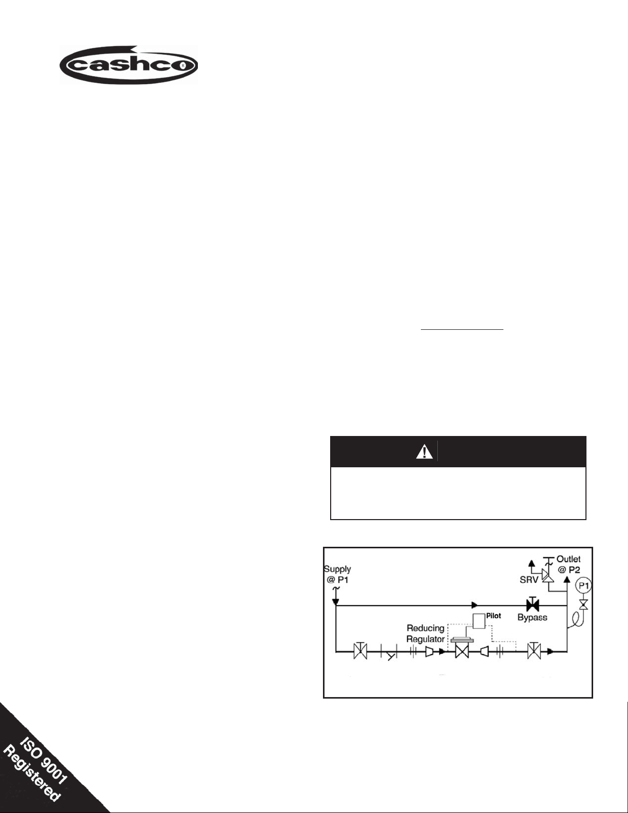
3. Install block valves and pressure gauges to pro vide means for adjustment, operation, bypass,
or removal of the regulator. A pipeline strainer
is recommended before inlet to remove typical
pipe line debris from entering valve and damaging
internal “soft goods”, primarily the dynamic seal.
ABBREVIATIONS
CW – Clockwise
CCW – Counter Clockwise
ITA – Inner Trim Assembly
CAUTION
Installation of adequate overpressure pro tec tion is recommended to pro tect the reg u la tor from overpressure and
all down stream equip ment from damage in the event of
regulator failure.
Model PGR-1
Page 2
SECTION IV
CAUTION
DO NOT HYDROSTATIC TEST THROUGH AN IN STALLED
UNIT; ISOLATE REGULATOR FROM TEST. The "OUTLET
RATING" as printed on the name plate is the rec om mend ed
“upper op er at ing limit” for the sens ing di a phragm. Higher
pres sures could cause internal dam age. In ad di tion, note
on the nameplate that the Inlet and Outlet pres sure and
temperature ratings are at different levels.
IV. PRINCIPLE OF OPERATION
1. When a loading pressure – P
the top side of a diaphragm, the outlet controlled
pressure – P
– will balance at approximately
2
.90 – .98 of the loading pressure - PL.
– is applied to
Load
SECTION V
V. STARTUP
1 Start with the block valves closed.
2. Movement occurs as pressure variations register
on the diaphragm. The registering pressure is the
outlet, P
, or downstream pressure. The loading
2
pressure fl uid op pos es di a phragm move ment.
As outlet pres sure drops, the loading pressure
push es the di a phragm down, opening the port; as
outlet pres sure increases, the diaphragm pushes
up and the port opening closes.
3. A diaphragm failure will tend to cause the reg u la tor
to fall below setpoint. A loss of loading pres sure
while inlet pressure is imposed will cause the
regulator to fail close.
pressure upwards until the main valve is fl owing.
Observe the outlet pressure gauge to ensure not
overpressurizing.
CAUTION
Do not walk away and leave a bypassed reg u la tor unattended!
2. Rotate the adjusting screw (47) on the pilot valve
CCW so that main regulator is trying to be con trolled
at 0 psig pressure. DO NOT rotate the adjusting
screw on the stabilizer, stabilizer was preset and
calibrated at the factory.
3. DO NOT rotate knob on metering valve, it was
preset at the factory at 2.5 to 3 full revolutions from
closed position. DO NOT close metering valve.
4. If it is a “hot” piping system, and equipped with
a bypass valve, slowly open the bypass valve
to preheat the system piping and to allow slow
ex pan sion of the piping. Closely monitor outlet
(down stream) pressure via gauge to ensure not
over-pressurizing. NOTE: If no bypass valve is
in stalled, extra caution should be used in starting
up a cold system; i.e. do everything slowly.
5. Crack open the outlet (downstream) block valve
to approximately 10% full open.
6. Slowly open the inlet (upstream) block valve to
about 25% open. Rotate the adjusting screw
(47) on the pilot valve CW to increase setpoint
7. Continue to slowly open the inlet (upstream) block
valve until fully open.
8. Continue to slowly open the outlet (downstream)
block valve, especially when the downstream piping system isn’t pressurized. If the outlet (down stream) pressure exceeds the desired pres sure,
close the inlet block valve and go to Step 2. Close
bypass valve approximately 25%, and re peat
pro ce dure.
9. When fl ow is established steady enough that the
outlet (downstream) block valve is fully open, begin
to slowly close the bypass valve if installed.
10. Develop system fl ow to a level near its expected
normal rate, and reset the regulator set point by
rotating the adjusting screw (47) on the pilot valve
CW to change the setpoint to the desired outlet
pressure level. If system pressure is unstable
rotate knob on metering valve in quarter turn increments CW or CCW to combat instability. DO
NOT rotate knob more than 6 full revolutions from
the closed position.
11. Reduce system fl ow to a minimum level and
observe pressure set point. Outlet pressure will
rise from the set point of Step. The max i mum rise
in outlet pres sure on de creas ing fl ow should not
exceed the 10%. If it does, consult factory.
2
IOM-PGR-1
Page 3
VI. SHUTDOWN
1. Shutoff inlet block valve.
SECTION VI
4. Relieve any trapped upstream and downstream
pressure and loading pres sure from PGR-1.
2. Allow suffi cient time for the line pressure down-
stream of the inlet block valve to bleed down.
3. Shutoff the outlet block valve.
SECTION VII
VII. MAINTENANCE
WARNING
SYSTEM UNDER PRESSURE. Prior to per form ing any
maintenance, isolate the reg u la tor from the system and
relieve all pressure. Failure to do so could result in personal injury.
A. General:
1. The main regulator body may be serviced
without re mov ing the regulator from pipeline.
The reg u la tor is designed with quick-change
trim to simplify maintenance.
2. Record the name plate information to req-
ui si tion repair parts for the regulator. This
in for ma tion should include: Serial Number
and Product Code.
5. The regulator may now be removed from the
pipe line or disassembled for inspection and pre ven ta tive main te nance while in-line.
Item Dynamic
No. Seal Type Part Description
4 .......................All....................................................Cage
5........................All......................................................Plug
9 ......................All .....................................Guide Bearing
10......................All......................................................Seat
13 .....................All ................................. Static Stem Seal
13.1 ............... All ...................... Upper Static Stem Seal
13.2 ............... All ......................Middle Static Stem Seal
13.3 ............... All ...................... Lower Static Stem Seal
14 ......................All..................................Cage O-ring Seal
15......................OR...........................Dynamic O-ring Seal
15.1...............UC............................Dynamic U-cup Seal
15.2............... UC.......................................Seal Retainer
B. Main Valve Disassembly:
1. Shut down system in accordance Section
VI.
2. Disconnect the external sensing line from
the pilot valve sensing port.
3. Refer to Section IX for recommended repair
parts. Only use original equipment parts
sup plied by Cashco for re build ing or re pair ing reg u la tors.
4. Owner should refer to owner's procedures
for removal, handling, cleaning and disposal
of nonreuseable parts, i.e. gaskets, etc.
NOTE: On regulators originally supplied as
“special clean” – Opt-56, maintenance must
include a level of cleanliness equal to Cashco
cleaning standard #S-1542.
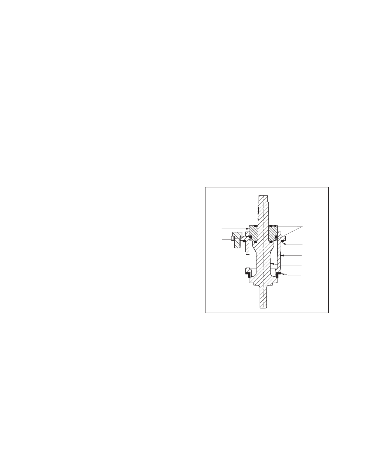
5. The Inner Trim is re moved and replaced back
in the body (1) as an assemblage of parts.
The Inner Trim Assembly, here in af ter called
ITA, consists of following parts: (See Figure
1)
A detailed view of the dynamic side seal
parts is shown on page 5.
3. Though it is possible to disassemble the
valve unit while installed in a pipeline, it is
rec om mend ed that all maintenance be done
in a shop. The instructions hereafter will assume in shop disassembly. Remove valve
from pipeline.
4. Place the main valve unit in a vise with the
cover dome (2) upwards.
5. Loosen all fi tings and remove tubing that
connect the inlet fi lter to the stablizer, the
cover dome to the metering valve and the
outlet of the metering valve to the outlet of
the body.
6. Loosen and remove the two nuts (24) that
secure the mounting bracket (3) and pilot to
the cover dome (2). Set pilot assembly aside.
Place match marks on the cover dome fl ange
to mark the location for the mounting bracket
and two longer bolts (23).
IOM-PGR-1
3
Page 4
7. Loosen the diaphragm fl ange bolts (23) and
nuts (24) uniformly and remove.
8. Place matchmarks on body (1) and cover
dome (2) fl anges. Remove cover dome.
9. With wrench grasp and hold the milled “fl ats”
on top of the valve plug (5) stationary. Rotate
di a phragm nut (11) CCW and remove .
10. Remove upper diaphragm plate (7).
11. Remove diaphragm (6) and o-ring upper stem
seal (13). Examine diaphragm to determine
whether failed; determine if op er at ing conditions are ex ceed ing pressure, pressure drop
or temperature limits.
12. Re move lower diaphragm pusher plate (8).
13. Rotate the cage bolts (22) CCW evenly in single
revolution increments. Regulator con tains a
lower return spring (18); the ITA should rise
up as the cage cap screws are evenly backed
out. A down wards holding force should be
ap plied to the top of the guide bearing (9) to
pre vent the ITA from pop ping up as the last
threads of the cage bolts are backed out.
14. Remove the ITA by pulling up on the valve
plug (5). Set ITA aside.
d. Examine the com po nent(s) (15 or 15.1,
15.2) of the dy nam ic side seal to de ter mine if sig nifi cant leakage was oc cur ring.
If the dy nam ic side seal shows signs of
sig nifi cant leakage, de ter mine if op er at-
ing con di tions are ex ceed ing pres sure,
pres sure drop, or tem per a ture limits.
Remove dynamic side seal com po nents.
Special care should be taken when using “tools” to remove the components to
ensure that no scratches are imparted
to any portion of the guide bearing (9)
groove.
e. Remove o-ring lower stem seal (13) from
plug (5).
f. Remove seat (10); examine for signs of
leakage. If seat ring shows signs of signifi cant leakage, determine if op er at ing
con di tions of pressure, pressure drop, or
temperature are ex ceed ing limits.
913
15
14
4
15. Remove the lower return spring (18) from
within the body (1) cavity.
16. Remove cage o-ring seal (14). It may have
been removed when the ITA was lifted out of
the body.
17. Remove internal sensing drilled plug (19) using 5/32" (4 mm) allen wrench.
18. Remove body (1) from vise. Clean all re us able
metal parts according to owner's pro ce dures.
C. Disassembly of the ITA:
1. See Figure 1 for details:
a. While holding the cage (4) pull the valve
plug (5) down wards and thru of the guide
bear ing (9) and out the bottom of the cage.
b. Remove the guide bearing (9) from the
upper end of the cage (4).
c. Remove o-ring middle stem seal (13) from
guide bearing (9).
5
10
Figure 1: Assembled ITA,
D. Inspection of Parts:
1. After inspection remove from the work area
and dis card the old “soft goods” parts (i.e. orings, di a phragms, seals, gaskets, etc.) after
in spec tion. These parts MUST be re placed
with fac to ry supplied new parts.
2. Inspect the metal parts that will be reused. The
parts should be free of surface con tam i nants,
burrs, oxides, and scale. Rework and clean
parts as necessary. Surface con di tions that
affect the regulator performance are stated
below; replace parts that can not be re worked
or cleaned.
4
IOM-PGR-1
Page 5
3. QC Requirements:
a. Valve plug (5);
1. 16 rms fi nish on its seating surface
for tight shutoff.
2. No major defects on bottom guide
spin dle.
b. Cage (4);
1. 16 rms fi nish on cylinder bore. No
“ledges” formed due to wear from
moving dynamic side seal (27) or
wiper seal (16).
c. Lower guide bushing (24) (non-re place-
able):
1. 16 rms fi nish on bore.
2. Max 0.015 inch (0.38 mm) clearance
be tween valve plug (20) spindle and
lower guide bushing (24).
d. Internal sensing drilled plug (32);
1. Ensure that bore is minimum 0.125
inch (3.20 mm). Drill out as required.
4. Staging Material for Reassembly.
a. Inspect and clean parts, as necessary,
from the spare parts kit. (See Article VII
A.4. comments concerning special cleaning.
b. Lay out all the regulator parts and check
against the bill of material.
E. Reassembly of the ITA:
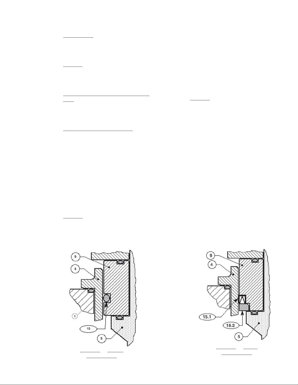
1. Installation of dynamic side seal (15).
a. Type OR:
1. Stretch o-ring seal (15) over lower
cir cum fer ence of guide bear ing (9),
tak ing care not to “cut” o-ring seal.
Using thumbs, work the o-ring seal
up and into the groove of the guide
bearing. NOTE: A very slight amount
of fl uid and elas tomer compatible
lu bri cant is rec om mend ed as an
in stal la tion aid.
2. Position guide bearing (9) over top
of the upper end of cage (4) properly
oriented. Using thumbs, evenly press
guide bearing into the cage, ensuring not to “cut” o-ring seal. Continue
pressing guide bearing into cage until
in ap prox i mate fi nal position.
b. Type UC:
1. Stretch u-cup seal (15.1) over lower
circumference of guide bear ing (9),
taking care not to “cut” u-cup seal on
the protruding shelf that is part of the
guide bear ing's groove. Ensure that
the u-cup seal is oriented with the
center-open-downwards as shown
in image below, as the u-cup seal
depends upon the P1-Inlet Pres sure
to pressure activate the seal for proper
sealing action.
2. Position guide bearing (9) over top
of the upper end of cage (4) properly oriented, until the cup seal edge
touches the upper lip of the cage
(4). While gently applying force to
press the guide bearing (9) into the
cage, simultaneously use fi ngers to
lightly press the edges of the u-cup
seal inwards into the groove of the
guide bearing until the u-cup seal
(15.1) “slips into” the cage (19). DO
NOT USE TOOLS, LUBRICANT, OR
HEAVY FORCE TO ENGAGE THE
U-CUP SEAL INTO THE CAGE .
IOM-PGR-1
Type OR — O-Ring
Dynamic Seal
Type UC — U-Cup
Dynamic Seal
5
Page 6

2. Place properly oriented seat (10) onto its
shoul der at the lower end of cage (4).
3. Place new o-ring lower stem seal (13) into
groove of valve plug (5).
4. Insert valve plug (5) upwards through lower
end of cage (4) and through the center hole
in guide bearing (9). Hold plug and cage
together in the closed position.
5. Place an oversized nut or stack of wash ers,
the same approximate height of the up per
diaphragm plate (7) and the lower diaphragm
plate (8), over the upper end of valve plug
(5) and temporarily secure with diaphragm
nut (11), manually tightened. Do NOT al low
valve plug to rotate against seat (10) during
tightening.
6. This completes ITA preliminary/partial reassembly.
F. Main Valve Reassembly:
1. Place body (1) in a vise fl ange face up.
2. Reinstall internal sensing drilled plug (19) with
compatible thread sealant.
3. Insert the lower return spring (18) into the
body (1).
4. Fit the cage o-ring seal (14) into the body
groove.
5. With the ITA held manually in the closed po si tion, insert ITA into body (1).
6. Properly align bolt holes in the cage with
the holes in the body, as there is only one
circumferential location pos si ble for this align ment. Apply downward force to the top of the
cage (4) until the ITA is lowered suf fi cient ly
to engage the cage bolts (22) into the body
(1). Engage all of the cage bolts, Rotate the
cage bolts in one-half revolution increments
to pull down the ITA evenly, taking care NOT
TO “AN GLE” the ITA in the body. Torque the
cage bolts to 13-15 ft-lbs. (17.6-20.3 N-m).
9. Position lower diaphragm plate (8) over upper end of plug (5) with tongue and groove
“groove” side up.
10. Place new o-ring upper stem seal (13) over
upper end of valve plug (5).
11. Place diaphragm (6) over end of valve plug
(5).
12. Place upper diaphragm plate (7) over upper
end of plug (5) with tongue and groove “ridge”
side down.
13. Place lubricant on valve plug (5) thread ed end.
Engage diaphragm nut (11) with upper end
of valve stem (5) as far as possible manually.
Place a wrench on diaphragm nut and a torque
wrench on the upper end of valve plug . Hold
torque wrench sta tion ary and rotate diaphragm
nut (7) to the following torque values:
Body Size
in (DN)
1/2" - 1" (15 - 25) 60 - 70 (81 - 95)
2" (50) 120 - 130 (163 - 176)
3" - 4" (80 - 100) 180 - 200 (244 - 271)
Torque Value
Ft-lbs (N-m)
DO NOT allow valve plug (20) to rotate
against seat ring (21) during tightening.
14. Aligning matchmarks and bolt holes, place
cover dome (2) onto body (1).
15. Reinstall all fl ange bolts (23) and nuts (24)
with nameplate (26) located under one bolt
head. Hand-tighten nuts. Make sure to install
the two longer bolts for the pilot bracket in the
correct location.
16. Evenly tighten the boltin in an alternating
cross pattern in one revolution increments to
the following torque values:
Body Size
in (Dn)
1/2" - 2" (15 - 50) 30 - 35 (41 - 47)
3" - 4" (80 - 100) 45 - 50 (61 - 69)
Torque Value
Ft-lbs (N-m)
G. Pilot Valve Disassembly:
7. Remove temporarily installed diaphragm nut
(11) and spacers of previous Step E.5. this
WARNING
section.
SYSTEM UNDER PRESSURE. Prior to per form ing any
8. Place new o-ring middle stem seal (13) into
groove of guide bearing (9) upper surface.
6
maintenance, isolate the reg u la tor from the system and
relieve all pressure. Failure to do so could result in personal injury.
IOM-PGR-1
Page 7

1. Shut down system in accordance Section VI.
2. Disconnect the external sensing line, from the
pilot valve sensing port.
3. Loosen all fi tings and remove tubing that con-
nect the inlet fi lter to the stablizer, the cover
dome to the metering valve and the outlet of
the metering valve to the outlet of the body.
4. Loosen and remove the two nuts (24) that
secure the mounting bracket (3) and pilot to
the cover dome (2).
5. Remove pilot assembly from main valve.
6. Place the pilot valve body (31) in a vise with
the spring chamber (32) upwards.
16. Remove return spring (41), ball holder (39),
and ball (52).
17. Place socket wrench over seat (37) and rotate
CCW to remove from body.
18. Remove body (1) from vise. Clean all re us able
metal parts according to owner's pro ce dures
H. Pilot Valve Reassembly:
1. Place body (31) in a vise fl ange face down.
2. Apply "Gasoila" or equivalent, thread sealant
to the threads of the seat (37). Engage the
seat threads into the body and apply 20 - 25
ft-lbs. torque. Place the ball (52), ball holder
(39) and return spring (41) onto seat.
7. Loosen adjusting screw nut (48) one revolution CCW. Relax range spring (34) forces
by rotating adjusting screw (47) CCW until
removed from spring chamber (32).
8. Loosen the diaphragm fl ange bolts (49) and
nuts (51) uniformly and remove bolting.
9. Place match marks on body (31) spring chamber (32) fl anges. Remove spring chamber.
10. Remove spring button (35), range spring (34)
and pressure plate (36).
11. Remove diaphragm (43).Examine diaphragm
to determine whether failed; determine if op er at ing conditions are exceeding pressure,
pressure drop or temperature limits. If just
replacing the diaphragm, proceed to Step H.9
and skip the following instructions.
12. Grasp pusher post (42) and lift up to remove.
Place socket wrench over retainer (40) and
rotate CCW to remove from body.
13. Remove seal gasket (45), piston seal (44) and
a second seal gasket (45) from bore inside
the body.
14. To remove the stem (38), remove the body
from the vise and slowly turn upside down.
Stem will slide out of the body, Do Not let the
stem fall and hit the fl oor.
15. Place body (31) in a vise with the body cap
(33) upwards. Rotate cap bolts (5) CCW to
remove bracket and body cap. Remove cap
seal (46).
3. Place the o-ring (46) into the groove in the
body cap (33) and place onto the body.
Position the bracket on the body cap and reinstall cap bolts (50). Make sure the return
spring (41) fi ts inside the bore of the body
cap. Tighten nuts evenly in a star crossing
pattern. Apply 15 - 18 ft-lbs. torque to tighten
the cap bolts.
4. Remove body from the vise. Reinstall body
again in vise with the bolt fl ange facing up.
5. Insert the stem (38) into the center hole of
the body and the seat (37), square end fi rst.
6. Place one seal gasket (45), one piston seal
(44) and one seal gasket (45) into the center
bore on top of the stem ((38). See Detail "A".
Ensure to align the seal and gaskets so they
are centered inside the threaded bore hole.
7. Engage the retainer (40) threads into the
center bore hole to hold the piston seal and
gaskets in place and apply 75 in-lbs. torque.
to tighten.
8. Insert pusher post (42) into retainer (40).
9. Place diaphragm (43) on bolt fl ange, centered
between bolt holes. Center the pressure
plate (36) on top of the diaphragm.
10. Place range spring (34) in center of the pressure plate (36) cup. Apply Mobile XHP 222
grease or equivalent into recessed area of
the spring button (35) and place on top of the
range spring. (Also lubricate the threads of
the adjusting screw lightly).
IOM-PGR-1
7
Page 8

11. Engage threads of the adjusting screw (47)
into the spring chamber (32) three or four
revolutions and place the spring chamber
over the spring button and spring.
12. Align the match marks on the body and spring
chamber fl anges. NOTE: Vent hole in the
spring chamber should be directly above the
"sense port in the body.
13. Place fl ange bolts through holes in spring
chamber and body and engage nuts (51).
Tighten nuts evenly in a star crossing pattern.
Apply 15 - 18 ft-lbs. torque to fi nsih tightening.
Ensure to secure the name plate (53) under
one of the fl ange bolts (49) above the "inlet"
of the pilot.
14. Rotate adjusting screw (47) CW into the spring
chamber (32) to where the nut (48) comes in
contact with the top of the spring chamber.
Pilot valve set pressure should approach
the set point prior to removal from the piping
installation. Retighten nut (48).
BODY
(INSIDE)
ELEMENT
COVER
Inlet Filter
K. Disassembly of the Stabilizer:
I. Mounting Pilot Valve to Main Valve:
1. Place the bolt holes for the mounting bracket
over the the two longer bolts (23) installed
throught the top of the cover dome (2). Engage
the fi nal two nuts (24) and secure tight.
2, Re-install tubing and fi ttings that previously
connected the inlet fi lter to the stablizer, the
cover dome to the metering valve and the
outlet of the metering valve to the outlet of
the body.
3. Re-connect the external sensing line to the
pilot valve sensing port.
WARNING
SYSTEM UNDER PRESSURE. Prior to per form ing any
maintenance, isolate the reg u la tor from the system and
relieve all pressure. Failure to do so could result in personal injury.
J. Changing the fi lter element:
1. Maintenance procedures hereinafter are
based upon re mov al of the stabilizer from
the pilot. Shut down system in accordance
Section VI.
2. Owner should refer to owner's procedures for
removal, handling, cleaning and disposal of
non reuseable parts, i.e. gaskets, etc.
3. Loosen fi ting and remove tubing that con-
nect the inlet fi lter to the stablizer, Remove
stabilizer from fi ttings that run between the
stabilizer and the pilot.
4. Securely stabilizer body (61) in a vise with
the spring chamber (62) oriented upwards
CAUTION
To prevent damage to body, use soft jaws when securng
the body in a vise. Position so that vise closes over the
inlet and the outlet connections.
DIAPHRAGM REPLACEMENT -
1. See Section IV.
2. Unscrew the fi lter cover from the body. Re-
move old element and replace with new element.
SPRING UNDER COMPRESSION. Prior to re mov ing the
spring chamber, relieve spring com pres sion by back ing
out the adjusting screw. Fail ure to so so may result in
fl ying parts that could cause personal injury.
WARNING
3. Screw cover on fi lter body and secure tight.
8
IOM-PGR-1
Page 9

1. Loosen adjusting screw nut (71) one revolution CCW. Relax range spring (75) forces
by rotating adjusting screw (68) CCW until
removed from spring chamber (62).
2. Loosen spring chamber (62) by placing
wrench on “fl ats” and rotating CCW making
sure not to use the fl at where the vent hole
is located.
3. Remove spring chamber (62), spring (75)
and spring button (65).
12. Reinstall ad just ing screw (68) with nut (71)
into the spring chamber (62).
13. Pressurize with air and spray liquid leak
de tec tor to test around body and spring
cham ber for leakage. En sure that an outlet
pressure is main tained during this leak test
of at least mid-range spring level; i.e. 20-80
psig (1.4-5.5 Barg) range spring, 50 psig
(3.4 Barg) test pres sure min i mum.
TRIM REPLACEMENT -
4. Remove the diaphragm subassembly
con sist ing of the pressure plate nut (70),
lock wash er (69), pres sure plate (63), diaphragm (72), push er plate seal (73) and
pusher plate (64).
5. Loosen pusher plate nut (70) and separate
all parts (63, 64, 69, 72 & 73) of the diaphragm subassembly.
6. Inspect pressure plate (63) to ensure no
de for ma tion due to over-pressurization. If
de formed, replace.
7. Clean all re us able metal parts according to
owner's pro ce dures.
8. Reassemble diaphragm subassembly
by plac ing pusher plate seal (73) over
thread ed post of pusher plate (64), placing diaphragm (72) and pressure plate
(63) over the threaded post. Assure the
pressure plate (63) is placed with curved
outer rim down next to the diaphragm (72)
surface. Place a thread sealant compound
on the threads of the push er plate post (64).
Apply 15 in-lbs torque to tighten the nut.
9. Place spring (75) over the pusher plate
nut (70) of the diaphragm subassembly.
10. Place multipurpose, high temperature
grease into de pres sion of spring button
(65) where ad just ing screw (68) makes
contact. Set spring but ton (65) onto range
spring (75); en sure spring button is laying
fl at on top of spring.
11. Rotate the spring chamber (62) CW by
hand into the threaded portion of the body
(61) ensuring not to cross thread. Continue
ro tat ing CW until fi rmly seated against the
upper di a phragm. Tighten to 30-35 ft-lbs
(41-47 N-m) torque value.
1. Secure stabilizer body (61) in a vise with
the body cap (66) oriented up and the
spring chamber (62) down wards.
CAUTION
To prevent damage to the body, use soft jaws when securing body in a vise. Position body so that vise closes over
the inlet and the outlet connections.
2. Loosen and remove body cap.
3. Remove piston spring (67), and piston
(74). Note that the seat and piston guide
are in te gral parts of the body (61) cast ing.
Inspect integral seat and guide for ex ces sive
wear, espe cially at seat sur fac es. Replace if
worn, nicked or de pressed. If integral seat
is nicked, use seat lapping com pound to
remove.
NOTE: Pis ton (74) assembly is a com po si-
tion seat, Cashco, Inc. does not recom mend
at tempt ing to remove the com po si tion seat.
If composition seat is damaged, re place
entire piston assembly.
4. Clean fl at mating surfaces of body (61) to
body cap (66) shoulder. Be careful not to
scratch either surface.
5. Clean debris from within the body (61) cavity. Parts to be reused should be cleaned
ac cord ing to own er's pro ce dures.
6. Slide the post end of the piston (74), slowly
into the body cavity.
7. Place piston spring (67) over spring hub of
the piston (74).
8. Apply pipe thread sealant to the body cap
(66) threads. Thread body cap into body.
When body cap is fully down against body
at the body cap shoulder, impact the body
cap into the body tight. NOTE: When unit is
put into service and pressurized, these two
parts seal metal-to-metal with no gasket.
IOM-PGR-1
9
Page 10

9. Bench test unit for suitable operation.
NOTE: Regulators are not tight shutoff devices. Even if pressure builds up beyond set
point, a reg u la tor may or may not develop
bubble tight shutoff. In general, tighter
shutoff can be expected with composition
seat.
10. Pressurize with air and spray liquid leak
de tec tor to test around body cap (66) and
body (61) for leak age. Test pres sure should
be a mini mum of 100 psig (6.9 Barg) at the
inlet.
11. Remove body from vise, rotate down side
up and secure body in vise with body cap
down.
12. Reassemble diaphragm subassembly by
plac ing pusher plate seal (73) over thread ed
post of pusher plate (64), placing diaphragm
(72) and pressure plate (63) over the
threaded post. Assure the pressure plate
(63) is placed with curved outer rim down
next to the diaphragm (72) surface. Place
a thread sealant compound on the threads
of push er plate post (64). Apply 15 in-lbs.
torque to tighten the nut.
pressure is main tained during this leak test
of at least mid-range spring level; i.e. 20-80
psig (1.4-5.5 Barg) range spring, 50 psig
(3.4 Barg) test pres sure min i mum.
13. Place spring (75) over the pusher plate
nut (70) of the diaphragm subassembly.
14. Place multipurpose, high temperature
grease into de pres sion of spring button (65)
where ad just ing screw (68) makes contact.
(Also lubricate the threads of the adjusting
screw lightly).
15. Set spring but ton (65) onto range spring
(75); en sure spring button is laying fl at on
top of spring.
16. Rotate the spring chamber (62) CW by
hand into the threaded portion of the body
(61) ensuring not to cross thread. Continue
ro tat ing CW until fi rmly seated against the
upper di a phragm. Tighten to 30-35 ft-lbs
(41-47 N-m) torque value.
17. Rotate adjusting screw (68) CW into the
spring chamber (62) to where the nut (71)
comes in contact with the top of the spring
chamber. Stabilizer set pressure should
approach the set point prior to removal from
the piping installation.Retighten nut (71).
10
18. Pressurize with air and spray liquid leak
de tec tor to test around body and spring
cham ber for leakage. En sure that an outlet
IOM-PGR-1
Page 11

SECTION VIII
VIII. TROUBLE SHOOTING GUIDE
When trouble shooting this regulator there are many possibilities as to what may be causing problems. Many times, the regulator itself is not defective, but one or more of the accessories may be. Sometimes the pro cess may be causing diffi culties.
The key to effi cient trouble shooting is information and communication. The customer should try to be as precise as possible
in their explanation of the problem, as well as their understanding of the application and operating con di tions.
It is imperative the following information be provided by the customer:
• Type of Service (with fl uid properties) • Range of outlet pressure
• Range of fl ow rate • Range of temperature
• Range of inlet pressure • Range of ambient temperature
Pressure readings should be taken at every location where pressure plays a role - i.e., regulator inlet (as close as possible to
inlet port), regulator outlet (as close as possible to outlet port), etc.
Following are some of the more common complaints along with possible causes and remedies.
1. Erratic regulation, instability or hunting.
Possible Causes Remedies
A. Sticking of internal parts. A. Remove internals, clean, and if necessary, replace.
B. Oversized regulator.
C. Metering Valve may not be adjusted correctly.
B. Check actual fl ow conditions; resize regulator for min i mum and maxi-
mum fl ow; if necessary, replace with smaller regulator.
C1. Rotate knob on metering valve in 1/4 turn increments to be more or
less sensitive to changes in P2 pressure. DO NOT fully close the
metering valve.
2. Downstream pressure will not reach desired setting.
Possible Causes Remedies
A. Supply pressure is down (confi rm on pressure
gauge.
B. Undersized regulator. B. Check actual fl ow conditions; resize regulator for min i mum and maxi-
C. Pressure loading system pressure restricted. C1. Clean fi lter.
D. Faulty loading pressure control device. D. Replace/repair loading pressure control device.
A. Increase supply pressure.
mum fl ow; if necessary, replace with larger regulator.
C2. Clean pilot valve.
3. Diaphragm continually breaks.
Possible Causes Remedies
A. Stem seals (13) which protect fl uorocarbon
elastomer in diaphragm assembly may have
deteriorated.
B. Diaphragm nut (11) may not be torqued to
correct value.
A. Replace with new stem seals (13).
B. Confi rm torque value in accordance with Section VII, F-13.
IOM-PGR-1
11
Page 12

4. Diaphragm continually breaks (all regulators).
Possible Causes Remedies
A. Differential pressure across diaphragm may
have exceeded limits.
A1. Be aware of limits as well as where the various pressures are acting.
Install pressure safety equipment as necessary.
5. Leakage at diaphragm fl ange.
Possible Causes Remedies
A. Body bolts not torqued properly. A. Torque to proper value (see Section VII, F-16).
B. Pressures at diaphragm may be too high. B. Consult factory.
6. Leakage across seat.
Possible Causes Remedies
A. Contamination (debris) in regulator. A. Remove internals, clean, and if necessary, replace sealing and
seating elements. *
B. Oversized regulator; valve plug operates
directly next to seat.
* Seat leakage may be diagnosed when a failure of the dynamic side seal has occurred. Inspect both potential internal leak paths.
B. Check actual fl ow conditions; resize regulator for minimum and maxi-
mum fl ow; if necessary, replace with smaller regulator.
SECTION IX
IX. ORDERING INFORMATION
NEW REPLACEMENT UNIT vs PARTS "KIT" FOR FIELD REPAIR
To obtain a quotation or place an order, please retrieve the Serial Number and Product Code that was stamped on
the metal name plate and attached to the unit. This information can also be found on the Bill of Material ("BOM").
a parts list that was provided when unit was originally shipped. (Serial Number typically 6 digits). Product Code
typical format as follows: (last digit is alpha character that refl ects revision level for the product).
–
–
7
PARTS "KIT" for FIELD REPAIR:
Contact your local Cashco, Inc., Sales Rep re sen-
NEW REPLACEMENT UNIT:
ta tive with the Serial Number and Product code.
Identify the parts and the quantity required to repair
Contact your local Cashco, Inc., Sales Rep re sen ta tive with the Serial Number and Product code.
the unit from the "BOM" sheet that was provided
when unit was originally shipped.
With this information they can provide a quotation
for a new unit including a complete description,
price and availability.
NOTE: Those part numbers that have a quantity indicated
under "Spare Parts" in column "A” refl ect minimum
parts required for inspection and rebuild, - "Soft
Goods Kit". Those in column “B” include minimum
trim replacement parts needed plus those "Soft
CAUTION
Do not attempt to alter the original construction of any
unit without assistance and approval from the factory. All
purposed changes will require a new name plate with appropriate ratings and new product code to accommodate
the recommended part(s) changes.
Goods" parts from column "A".
If the "BOM" is not available, refer to the crosssectional drawings included in this manual for part
identifi cation and selection.
A Local Sales Representative will provide quotation
for appropriate Kit Number, Price and Availability.
12
IOM-PGR-1
Page 13

Assembled View
METERING VALVE
IOM-PGR-1
13
Page 14

Main Body Assembly with
Dynamic O-ring Seal
Item No. Description
1 Body
2 Cover Dome
4 Cage
5 Plug
6 Diaphragm *
7 Upper Diaphragm Plate
8 Lower Diaphragm Plate
9 Guide Bearing
10 Seat *
11 Nut
12 Guide Bushing
13 Static Seal (Plug) *
14 Static Seal (Cage) *
14
Item No. Description
15 Dynamic Seal (Guide Bearing) *
18 Return Spring
19 Internal Sensing Plug
20 Pipe Plug (Dome)
22 Cage Bolts
23 Flange Bolts
24 Flange Nuts
* Recommended Spare Parts.
Items not shown
3 Mounting Bracket
15.2 Seal Retainer
16 Seal Retainer (Dynamic)
21 Pipe Plug (Body)
26 Name Plate
IOM-PGR-1
Page 15

Sense Port
Vent to Atmosphere
Pilot Inlet
Detail A
Pilot Assembly
Item No. Description
31 Body
32 Spring Chamber
33 Body Cap
34 Range Spring
35 Spring Button
36 Pressure Plate
37 Seat
38 Stem
39 Ball Holder
40 Retainer
41 Return Spring
42 Pusher Post
Item No. Description
43 Diaphragm *
44 Piston Seal *
45 Seal Gasket *
46 Seal (Body Cap) *
47 Adjusting Screw
48 Jam Nut
49 Flange Bolts
50 Body Cap Bolts
51 Flange Nuts
52 Ball *
53 Name Plate
* Recommended Spare Parts
IOM-PGR-1
15
Page 16

Inlet
Stabilizer
Item No. Description
61 Body
62 Spring Chamber
63 Pressure Plate
64 Pusher Plate
65 Spring Button
66 Body Cap
67 Piston Spring
68 Adjusting Screw
69 Lock Washer
70 Nut (Pressure Plate)
71 Nut
72 Diaphragm *
73 O-ring *
74 Piston *
75 Range Spring
Vent
Outlet
* Recommended Spare Parts
The contents of this publication are presented for informational purposes only, and while every effort has been made to ensure their accuracy, they are not to be construed as warranties or guarantees, express or implied, regarding the products or services described herein or their use or applicability. We reserve the right to modify
or improve the designs or specifi cations of such product at any time without notice.
Cashco, Inc. does not assume responsibility for the selection, use or maintenance of any product. Responsibility for proper selection, use and maintenance of any
Cashco, Inc. product remains solely with the purchaser.
Cashco, Inc.
P.O. Box 6
Ellsworth, KS 67439-0006
PH (785) 472-4461
Fax (785) 472-3539
www.cashco.com
email: sales@cashco.com
Printed in USA IOM-PGR-1
Cashco GmbH
Handwerkerstrasse 15
15366 Hoppegarten, Germany
PH +49 3342 4243135
Fax. No. +49 3342 4243136
www.cashco.com
email: germany@cashco.com
Cashco do Brasil, Ltda.
Al.Venus, 340
Indaiatuba - Sao Paulo, Brazil
PH +55 11 99677 7177
Fax. No.
www.cashco.com
email: brazil@cashco.com
 Loading...