


INSTALLATION, OPERATION & MAINTENANCE MANUAL (IOM)
MODEL P3
TWO STAGE CYLINDER GAS
PRESSURE REDUCING REGULATOR
SECTION I
I. DESCRIPTION AND SCOPE
The Model P3 is a pressure reducing regulator used to control downstream (outlet or P2 ) pressure. Available in
sizes 1/4" (DN8), 3/8" (DN10) and 1/2" (DN15). The unit is suitable for cylinder gaseous services. Refer to Technical Bulletin P3-TB for design conditions and selection recommendations.
SECTION II
IOM-P3
11/13
II. INSTALLATION
CAUTION
Installation of adequate overpressure protection
is recommended to pro tect the regulator from
over pres sure and all down stream equip ment
from dam age in the event of regulator failure.
1. An inlet block valve should always be installed.
2. If service application is continuous such that
shut down is not readily accomplished, it is recommended that an inlet block valve, outlet block
valve, and a manual bypass valve be installed.
3. Pipe unions should be installed to allow removal
from piping.
4. An outlet pressure gauge should be located ap proxi mately ten pipe diameters downstream, and
within sight.
5. All installations should include a downstream re lief de vice if the inlet pressure could exceed the
pres sure rating of any downstream equip ment or
the maximum outlet pressure rating of the unit.
6. Clean the pip ing of all foreign material including
chips, welding scale, oil, grease and dirt before
installing the reg u la tor. Strainers are rec om mend ed.
7. In plac ing thread seal ant on pipe ends pri or to
en gage ment, ensure that excess material is
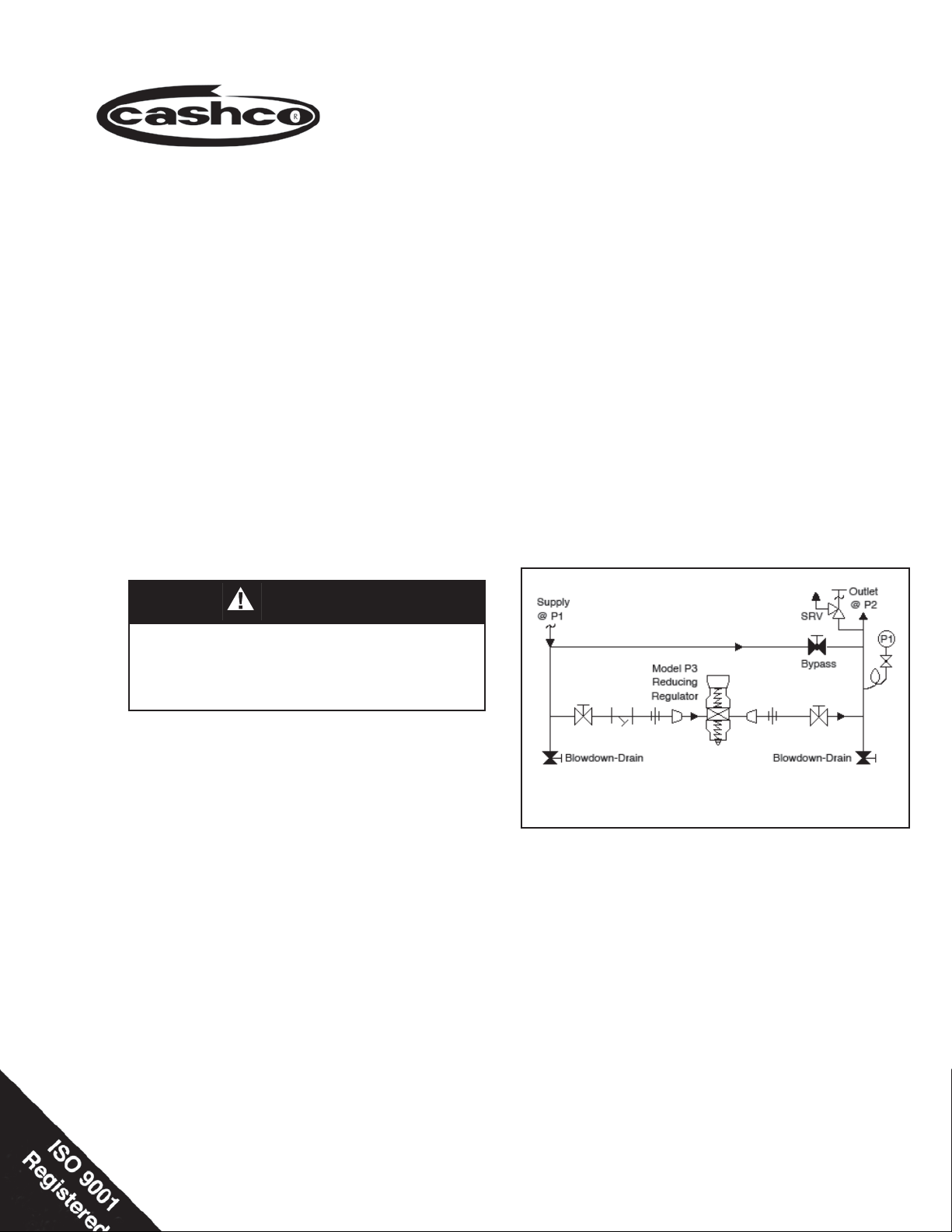
Recommended Piping Schematic
For Pressure Reducing Station
re moved and not allowed to enter the regulator
upon startup.
8. Flow Direction: Install so the flow direction
match es the inlet stamp on the main regulator
body (1).
9. For best performance, install in well drained hori zon tal pipe.
10. Basic Regulator - (Refer to Figure 2, Model P3):
Regulator may be rotated around the pipe axis
360°. Recommended position is with 2nd stage
knob (4) ver ti cal upwards.
11. Regulators are not to be buried un der ground.
12. For insulated piping systems, recommendation is
to not insulate regulator.

SECTION III
III. PRINCIPLE OF OPERATION
1. Movement occurs as pressure variations register on the diaphragms (7.1). The registering
pres sure is the outlet, P2, or downstream pres sure. The range springs (15) oppose move ment
of the di a phragms. As outlet pressure drops,
SECTION IV
IV. STARTUP
CAUTION
The maximum outlet pressure is stamped on the
body as the upper range spring pres sure level, and
is the rec om mend ed “upper operative limit” for the
sens ing diaphragms (see Sec tion IV. Startup, Step
7). Higher press ures could dam age the diaphragms.
(Field hydro static tests fre quent ly de stroy di a phragms. DO NOT HYDRO STATIC TEST THRU AN
IN STALLED UNIT; ISO LATE FROM TEST.)
1. Start with the block valves closed. A by pass
valve may be used to maintain out let pres sure
in the down stream sys tem without changing the
fol low ing steps.
2. Relax 2nd stage range spring (15) by turning knob
(4) counter clockwise (CCW) until ro ta tion comes
to a complete stop.
3. If it is a “hot” piping system, and equipped with
a bypass valve, slowly open the bypass valve
to preheat the system piping and to allow slow
ex pan sion of the piping. Closely monitor outlet
(down stream) pres sure via gauge to ensure not
over-pressurizing. NOTE: If no bypass valve is
in stalled, extra caution should be used in starting
up a cold system; i.e. do everything slowly.
4. Crack open the outlet (downstream) block valve.
the range springs push the di a phragms down,
open ing the ports; as outlet pres sure in creas es,
the di a phragms push up and the ports close.
2. A complete diaphragm failure will cause the reg u la tor to fail open.
5. Slowly open the inlet (upstream) block valve ob-
serv ing the outlet (downstream) pressure gauge.
De ter mine if the regulator is fl owing. If not, slowly
rotate knob (4) clock wise (CW) until fl ow begins.
6. Continue to slowly open the inlet (upstream) block
valve until fully open.
7. Continue to slowly open the outlet (downstream)
block valve, especially when the downstream pip ing system isn't pressurized. If the outlet (down stream) pressure exceeds the desired pres sure,
close the block valve and go to Step 2, then return
to Step 4.
8. When fl ow is established steady enough that the
outlet (downstream) block valve is fully open, be gin to slowly close the bypass valve if installed.
9. Develop system fl ow to a level near its expected
normal rate, and reset the regulator set point by
turning knob (4) CW to increase outlet pressure,
or CCW to reduce outlet pressure.
10. Reduce system fl ow to a minimum level and
ob serve set point. Outlet pressure will rise from
the set point of Step 9. The maximum rise in
outlet pressure on decreasing fl ow should not
exceed the stated up per limit of the range spring
by greater than 10%. Example with 2-100 psig
(.14-6.9 Barg) range spring at low fl ow the outlet
pressure should not exceed 110 psig (7.6 Barg),
if it does, con sult factory.
V. SHUTDOWN
1. On systems with a bypass valve, and where sys tem pressure is to be main tained as the reg u la tor
is shut down, slowly open the bypass valve while
closing the inlet (up stream) block valve. Fully
close the inlet (up stream) block valve. (When on
bypass, the sys tem pres sure must be con stant ly
observed and man u al ly reg u lat ed. Close the
outlet (down stream) block valve.
SECTION V
2. If the regulator and system are to both be shut
Do not walk away and leave a bypassed
regulator unattended.
down, slowly close the inlet (upstream) block
valve. Close the outlet (downstream) valve only
if reg u la tor re mov al is required.
CAUTION
IOM-P32
VI. MAINTENANCE
WARNING
SYSTEM UN DER PRES SURE. Prior to per form ing
any maintenance, isolate the reg u la tor from the
sys tem and relieve all pres sure. Failure to do so
could result in personal injury.
A. General:
SECTION VI
1. Maintenance procedures hereinafter are
based upon re mov al of the regulator unit from
the pipeline where in stalled.
2. Owner should refer to owner's procedures for
removal, handling, cleaning and disposal of
non reuseable parts, i.e. gaskets, etc.
3. Refer to Figure 2 for basic reg u la tor and Figure 1 for the diaphragm sub as sem bly.
CAUTION
To prevent damage to body, use soft jaws when
placing body in a vise.
5
WARNING
SPRINGS UNDER COMPRESSION. Prior to re mov ing spring chambers, relieve range spring
com pres sion by turn ing 2nd stage knob (4)
CCW until ro ta tion comes to a com plete stop.
Fail ure to so so may result in fl ying parts that
could cause personal injury.
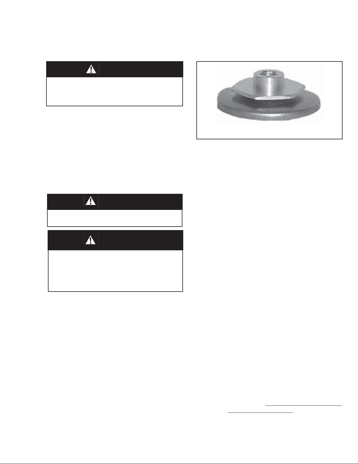
Figure 1: Diaphragm Subassembly
C. 1st Stage Diaphragm Replacement:
1. Invert the body and securely install in a vise
with acron nut (4) directed upwards.
2. Rotate nut CCW and remove. Measure the
height of the exposed adjusting screw and
record that value here. ___________.
3. Relax 1st stage range spring (15) by turning adjusting screw (2) CCW until spring
compression is released. NOTE: It is not
necessary to remove adjusting screw before
re mov ing the spring cham ber (6) from the
body (1).
4. Remove the spring chamber (6) by grasp ing
the fl ats and turning CCW. NOTE: Upon
re mov al, the range spring (15), range spring
clip (16), and spring button (5) should re main
inside the spring cham ber.
B. 2nd Stage Diaphragm Replacement:
1. Securely install the body (1) in a vise with
knob (4) directed upwards.
2. Relax 2nd stage range spring (15) by turning knob (4) CCW until rotation comes to a
com plete stop. NOTE: It is not necessary
to remove knob (4) before re mov ing spring
cham ber (6) from the body (1).
3. Remove the spring chamber (6) by grasp ing
the fl ats and turning CCW. NOTE: Upon
re mov al, the range spring (15), range spring
clip (16), and spring button (5) should re main
inside the spring cham ber.
4. Remove 2nd stage diaphragm subassembly
(7) con sist ing of the actuator nut (7.3), di a phragm (7.1), ac tu a tor post (7.2), actuator
gasket (7.4), actuator o-ring (7.5). Remove
di a phragm gas ket (10).
IOM-P3
5. Remove 1st stage diaphragm subassembly
(7) con sist ing of the actuator nut (7.3), di a phragm (7.1), ac tu a tor post (7.2), actuator
gasket (7.4), actuator o-ring (7.5). Remove
di a phragm gas ket (10).
NOTE: The following Steps 6 thru 9 apply to
both the fi rst and second stage diaphragm
sub as sem blies (7).
6. Remove actuator nut (7.3) and separate all
parts of the diaphragm subassembly (7,).
7. Clean body (1) diaphragm fl ange surfaces
and all re us able parts according to owner's
procedures. Do not scratch di a phragm
gas ket seat ing sur face. NOTE: On reg u-
la tors origi nally sup plied as “oxygen clean”,
Option-M, main tenance must in clude a level
of clean li ness equal to Cash co clean ing stan dard #S-1134. Contact factory for details.
3