

Cashco DL User Manual
INSTALLATION, OPERATION & MAINTENANCE MANUAL (IOM)
IOM-D/DL
12-13
MODELS D and DL
PRESSURE REDUCING REGULATORS
SECTION I
I. DESCRIPTION AND SCOPE
The Model D is a pressure reducing regulator used to control downstream (outlet or P2) pressure. Sizes are 3/8" (DN10),
1/2" (DN15), 3/4" (DN20) and 1" (DN25). With proper trim utilization, the unit is suit able for liquid, gase ous, or steam
serv ice. Refer to Technical Bulletin D-TB for design conditions and se lec tion recommendations.
The Model DL is also a pressure reducing regulator similar to above Model D. Sizes are 1-1/2" (DN40) and 2" (DN50).
(Model DL was formerly a Cashco Model D). Refer to Technical Bulletin DL-TB for design conditions and selection recommendations.
SECTION II
II. INSTALLATION
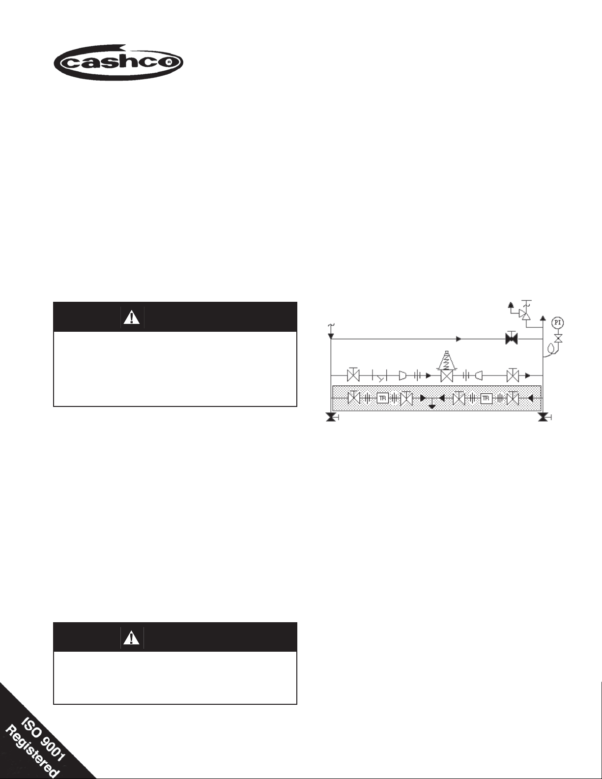
Outlet
@ P2
CAUTION
Supply
@ P1
SRV
For welded installations, all internal trim parts, seals
and diaphragm(s) must be removed from regulator body prior to welding into pipelne. The heat
of fusion welding will damage non-metallic parts if
not removed. NOTE: This does not apply to units
equipped with extended pipe nipples.
1. An inlet block valve should always be in stalled.
2. If service application is continuous such that shut down is not readily accomplished, it is rec ommended
that an inlet block valve, outlet block valve, and a
manual bypass valve be installed.
3. Pipe unions should be installed to allow re moval
from piping.
4. An outlet pressure gauge should be located ap prox i mate ly ten pipe diameters downstream and within
sight.
5. All installations should include a downstream re lief
device if the inlet pressure could exceed the pres sure rating of any downstream equip ment or the
maximum outlet pressure rating of the unit.
CAUTION
Installation of adequate overpressure pro tec tion is
recommended to pro tect the reg u la tor from overpressure and all down stream equip ment from damage
in the event of regulator failure.
Model D or DL
Reducing
Regulator
Blowdown-Drain Blowdown-Drain
(Shaded portion for steam/condensate systems)
Bypass
Recommended Piping Schematic
For Pressure Reducing Station
6. Clean the piping of all foreign material in clud ing
chips, welding scale, oil, grease and dirt be fore installing the regulator. Strainers are rec om mend ed.
7. In placing thread sealant on pipe ends prior to
en gage ment, ensure that excess material is re moved and not allowed to enter the regu la tor upon
startup.
8. Flow Direction: Install so the fl ow direction match es
the arrow cast on the body.
9. For best performance, install in well drained hori zon tal pipe, properly trapped, if a steam service
application.
10.A. Basic Regulator - (Refer to Figure 2): Regu la tor
may be rotated around the pipe axis 360o. Recom mended position is with spring cham ber ver ti cal
upwards. Ori ent such that the spring cham ber vent
hole does not collect rainwater or debris.

CAUTION
DO NOT HYDROSTATIC TEST THRU AN IN STALLED
UNIT; ISOLATE REGU LA TOR FROM TEST. The
upper range spring pressure level listed on the
nameplate or 100 psig (6.9 Barg) minimum is the
rec om mend ed “upper op era tive lim it” for the sens ing dia phragm (see Sec tion IV. Startup, Num ber 7.)
Higher pres sures could cause in ter nal dam age. In
addition, note on the name plate that the Inlet and
Outlet pres sure and tem pera ture ratings are at dif fer ent levels.
a. Recommended installation is with spring cham-
ber hang ing directly below the body in a vertical
down wards ori en ta tion. Al lows water to drain;
i.e. rainwater, et cet era.
b. Recommend inert purge gas to spring cham ber
thru vent hole and out drain hole.
11. Regulators are not to be di rect bur ied under ground.
12. For insulated piping systems, rec om men da tion is to
not insulate regulator.
10.B. Model D Cryogenic Regulator - Option D-5 or D-36
(Refer to Figure 4):
III. PRINCIPLE OF OPERATION
1. Movement occurs as pressure variations register on
the diaphragm. The registering pressure is the outlet, P2, or downstream pressure. The range spring
or loading pressure (Opt.-20) op pos es di a phragm
movement. As outlet pressure drops, the range
IV. STARTUP
1. Start with the block valves closed. A bypass valve
may be used to maintain outlet pres sure in the
downstream sys tem without chang ing the fol low ing
steps.
2. Relax the range spring by turning the ad just ing screw
counter clockwise (CCW) a min i mum of three (3) full
revolutions or reduce loading pressure (Opt.-20).
This re duc es the outlet (down stream) pres sure set
point.
3. If it is a “hot” piping system, and equipped with a
bypass valve, slowly open the bypass valve to preheat the system piping and to allow slow ex pan sion
of the piping. Ensure proper steam trap operation
if installed. Close ly monitor outlet (down stream)
pres sure via gauge to en sure not over-pres sur iz ing.
NOTE: If no bypass valve is installed, extra caution
should be used in start ing up a cold system; i.e. do
ev ery thing slow ly.
4. Crack open the outlet (downstream) block valve.
5. Slowly open the inlet (upstream) block valve ob serv ing the outlet (downstream) pressure gauge.
Determine if the reg u la tor is fl owing. If not, slowly
rotate the regulator adjusting screw (6) clock wise
(CW) or increase loading pressure (Opt.-20) until
fl ow begins.
2
13. Spring Chamber Vent Tap - Option D-25 or DL25: Pipe spring chamber vent opening to remote
lo ca tion. Orient so as not to take on rainwater.
SECTION III
spring or loading pressure pushes the dia phragm
down, opening the port; as outlet pres sure in creas es, the diaphragm push es up and the port opening
closes.
2. A complete diaphragm failure will cause the reg u la tor to fail open.
SECTION IV
6. Continue to slowly open the inlet (upstream) block
valve until fully open.
7. Continue to slowly open the outlet (downstream)
block valve, especially when the downstream pip ing
system isn't pressurized. If the outlet (down stream)
pressure exceeds the desired pres sure, close the
block valve and go to Step 2, then return to Step
4.
8. When fl ow is established steady enough that the
outlet (downstream) block valve is fully open, begin
to slowly close the bypass valve if installed.
9. Develop system fl ow to a level near its expected
normal rate, and reset the regulator set point by turning the adjusting screw (6) CW to increase outlet
pressure, or CCW to reduce outlet pressure.
10. Reduce system fl ow to a minimum level and ob serve
set point. Outlet pressure will rise from the set point
of Step 9. The maximum rise in outlet pressure on
decreasing fl ow should not exceed the stated upper
limit of the range spring by greater than 10%; i.e. 1040 psig (.69 - 2.8 Barg) range spring, at low fl ow the
outlet pres sure should not exceed 44 psig (3 Barg),
if it does, consult factory.
IOM-D/DL
SECTION V
V. SHUTDOWN
1. On systems with a bypass valve, and where sys tem
pressure is to be maintained as the reg u la tor is shut
down, slowly open the bypass valve while reducing
the loading pressure (Opt.-20) and slowly closing the
inlet (up stream) block valve. When all loading pressure is relieved, fully close the inlet (upstream) block
valve. (When on bypass, the system pressure must
be constantly observed and manually reg u lat ed.)
Close the outlet (down stream) block valve.
SECTION VI
VI. MAINTENANCE
A. General:
WARNING
SYSTEM UNDER PRESSURE. Prior to per form ing
any maintenance, isolate the regulator from the
system and relieve all pres sure. Failure to do so
could result in personal injury.
1. Maintenance procedures hereinafter are based
upon re mov al of the regulator unit from the pipeline where in stalled.
CAUTION
Do not walk away and leave a bypassed reg u la tor
unattended!
2. If the regulator and system are to both be shut down,
remove all loading pressure while slowly closing the
inlet (upstream) block valve. Close the outlet (downstream) valve only if reg u la tor removal is required.
3. Draw or embed a match mark between body
casting (1) and spring chamber casting (2) loading chamber (33) along fl anged area.
4. Remove all diaphragm nuts (9) and bolts (8).
5. Remove spring chamber (2), (loading chamber
33),range spring (14), spring button (4), pressure plate (3) and diaphragm(s) (12). NOTE:
Refer to the quan tity of diaphragms (12) in cor po rat ed per the bill of materials listing. Depending on outlet pres sure level, multiple metal
diaph ragms may be “stacked”.
2. Owner should refer to owner's procedures for
re mov al, handling, cleaning and disposal of
nonreusable parts, i.e. gaskets, etc.
3. Refer to Figure 2 for basic regulator. Refer to
Figure 4 for cryogenic regu la tor. For blow-ups
of Option-4 Stabilizer, refer to Figure 3.
B. Diaphragm Replacement:
1. Securely install the body (1) in a vise with
the spring chamber (2) loading chamber (33)
directed upwards.
WARNING
SPRING UNDER COMPRESSION. Prior to removing
fl ange bolts, relieve spring com pres sion by backing
out the ad just ing screw. Failure to do so may result
in fl ying parts that could cause personal injury.
2. Relax range spring (14) by turning adjusting
screw (6) CCW until removed from spring cham ber (2). NOTE: If the D-3 Option hand wheel is
utilized, the adjusting screw (6) and locknut (7)
are re placed respectively by hand wheel adjusting screw (20) and locking lever (21). Refer to
Figure 1.
6. Remove pusher plate (11) and inspect for a
fi t which limits its travel to a vertical direction.
Wear will show as ex ces sive wobble in push er
plate (11). If apparent, recommend trim removal
and inspection; go to Sub-Sec tion C fol low ing.
Re in stall pusher plate (11).
7. Inspect pressure plate (3) to ensure no de for ma tion due to over-pressurization. If de formed,
replace.
8. Clean body (1) and diaphragm fl ange. NOTE:
On regulators originally supplied as “ox y gen
clean”, Option D-5, D-36, D-55, or DL-55, maintenance must include a level of clean li ness
equal to Cashco cleaning standard #S-1134.
On reg u la tors originally supplied as “cleaned
for Phar ma ceu ti cal and Food ap pli ca tions” Op tion D-37 or D-37S, main te nance must in clude
a level of cleanliness equal to Cashco cleaning
stan dard #S-1576.
9. Place diaphragm gasket (13) on body (1) fl ange.
Position diaphragm(s) (12) into place. Vi su al ly
center pres sure plate (3) onto diaphragm(s)
(12), and set range spring (14) onto retainer hub
of pressure plate (3). (Opt.-20 does not utilize
spring skip to step 11.) NOTE: No dia phragm
gasket (13) for com po si tion dia phragm.
IOM-D/DL
3
 Loading...