

Page 1
INSTALLATION, OPERATION & MAINTENANCE MANUAL (IOM)
MODEL DA4
(Formerly DA3/4)
DIRECT-ACTING, PRESSURE LOADED
PRESSURE REDUCING REGULATOR
(Model DA3 was identical to DA4 except that the DA3 did not include a lower return spring.)
SECTION I
I. DESCRIPTION AND SCOPE
Model DA4 is a pressure reducing regulator used to control downstream (outlet or P2) pressure. Sizes are
1/2" (DN15), 3/4" (DN20), 1" (DN25), 1-1/4" (DN32), 1-1/2" (DN40), 2" (DN50), 3" (DN80) and 4" (DN100). With
proper trim uti li za tion, the unit is suitable for liquid, gaseous, or steam service. Refer to Technical Bulletin DA4-TB
for design conditions and selection recommendations. (NOTE: This product was formerly identifi ed as a Model
D4; a Model DA4 and D4 are one and the same product.)
This manual does not include instructions related to the various methods of pressure loading a Model DA4
main valve.
SECTION II
IOM-DA4
11-13
II. REFERENCES
Refer to Technical Bulletin DA4-TB for tech ni cal
specifi cations for this reg u la tor.
SECTION III
III. INSTALLATION
CAUTION
For welded installations, all internal trim parts, seals and
diaphragm(s) must be removed from reg u la tor body prior to
welding into pipeline. The heat of fusion welding will dam age non-metallic parts if not re moved. NOTE: This does
not apply to units equipped with extended pipe nip ples.
1. Regulator may be rotated around pipe axis 360
degrees. For ease of maintenance, the rec om mend ed position is with the cover dome (25)
up wards. In liquid service it is recommended
that the cover dome (25) be oriented down wards,
and that a cus tom er supplied and installed vent
valve be pro vid ed at the external sensing connection to bleed-off trapped gas/air under the
diaphragm.
2. Provide space below, above, and around reg u la-
tor for removal of parts during maintenance.
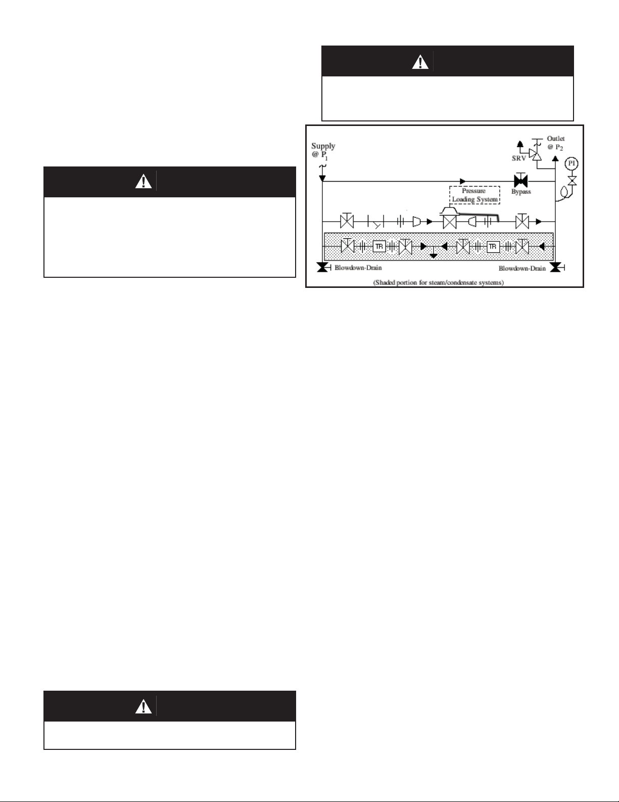
3. Install block valves and pressure gauges to pro-
vide means for adjustment, operation, bypass,
or removal of the regulator. A pipeline strainer
is recommended before inlet to remove typical
pipe line debris from entering valve and damaging
internal “soft goods”, primarily the dynamic seal.
ABBREVIATIONS
CW – Clockwise
CCW – Counter Clockwise
ITA – Inner Trim Assembly
CAUTION
Installation of adequate overpressure pro tec tion is recommended to pro tect the reg u la tor from overpressure and
all down stream equip ment from damage in the event of
regulator failure.
4. Downstream Sensing Installation Considerations
– Internal or External Sensing:
a. The regulator may be installed with internal or
external sensing. Unless otherwise spec i fi ed,
the regulator is supplied by factory with internal
sensing. The regulator may be con vert ed in
the fi eld to external sensing. (See Section VII
Maintenance, Part H – Converting Internal/
External Sensing.
b. Reference DA4-TB, Table DAG-11 for rec om-
men da tions for applying external pressure
sensing.
c. For internal sensing, no external line is re-
quired. For external sensing, use an external
control line. The line is connected from the
1/4" (DN8) NPT tap (Port 5 – See Fig. 6) on
the side of the body di a phragm fl ange to a
pressure tap down stream of the regulator.
Page 2
Use 1/4" or 3/8" (DN8 or 10) outer di am e ter
tubing or 3/8" (DN10) pipe having an inner
di am e ter equiv a lent to Schedule 40 pipe.
d. For condensable vapors (i.e. steam) slope the
external sensing line downward 2 to 5 de grees
to outlet piping to prevent water pock ets, which
allows the diaphragm chamber to always be
self draining. The external sensing line may
be sloped upward for liquids or gas es.
CAUTION
DO NOT HYDROSTATIC TEST THROUGH AN IN STALLED
UNIT; ISOLATE REGULATOR FROM TEST. The "OUTLET
RATING" as printed on the name plate is the rec om mend ed
“upper op er at ing limit” for the sens ing di a phragm. Higher
pres sures could cause internal dam age. In ad di tion, note
on the nameplate that the Inlet and Outlet pres sure and
temperature ratings are at different levels.
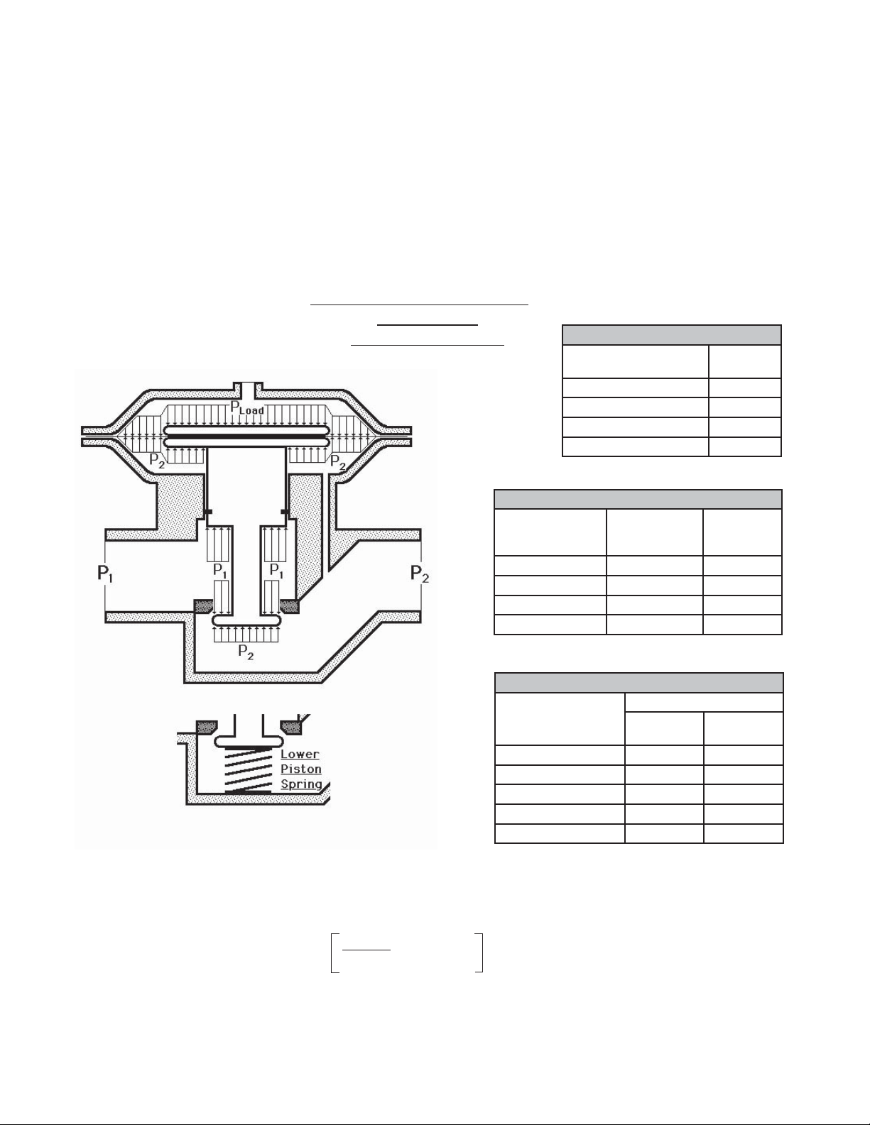
IV. PRINCIPLE OF OPERATION
1. When a loading pressure – P
the top side of a diaphragm, the outlet controlled
pressure – P
– will balance at approximately
2
.90 – .98 of the loading pressure - PL. (NOTE:
Fluc tu a tions in P1 – Inlet Pressure will cause a
deviation in P
– Outlet Pressure due to inverse
2
sym pa thet ic ratio effect.) See Section VIII.
2. Movement occurs as pressure variations register
on the diaphragm. The registering pressure is the
outlet, P
, or downstream pressure. The loading
2
– is applied to
Load
CAUTION
Installation of adequate overpressure pro tec tion is recommended to pro tect the reg u la tor from over pres sure and
all down stream equip ment from dam age in the event of
regulator failure.
Model DA4
SECTION IV
pressure fl uid op pos es di a phragm move ment. As
outlet pres sure drops, the loading pressure push es
the di a phragm down, opening the port; as outlet
pres sure increases, the diaphragm pushes up and
the port opening closes.
3. A diaphragm failure will tend to cause the reg u la tor
to fall below setpoint. A loss of loading pres sure
while inlet pressure is imposed will cause the
regulator to fail close. A com plete diaphragm failure
will cause the inlet process fl uid to mix with the
loading fl uid.
V. STARTUP
1 Start with the block valves closed.
2. Adjust the loading system pressure control de vice
so that main regulator is trying to be con trolled at
0 psig pressure.
3. If it is a “hot” piping system, and equipped with
a bypass valve, slowly open the bypass valve
to preheat the system piping and to allow slow
ex pan sion of the piping. Ensure proper steam
trap operation if installed. Closely monitor outlet
(down stream) pressure via gauge to ensure not
over-pressurizing. NOTE: If no bypass valve is
CAUTION
Do not walk away and leave a bypassed reg u la tor unattended!
2
SECTION V
in stalled, extra caution should be used in starting
up a cold system; i.e. do everything slowly.
4. Crack open the outlet (downstream) block valve
to approximately 10% full open.
5. Slowly open the inlet (upstream) block valve
to about 25% open. Adjust the loading system
pres sure control device setpoint pressure upwards
until the main valve is fl owing. Observe the outlet
pressure gauge to ensure not overpressurizing.
6. Continue to slowly open the inlet (upstream) block
valve until fully open.
7. Continue to slowly open the outlet (downstream)
block valve, especially when the downstream piping system isn’t pressurized. If the outlet (down stream) pressure exceeds the desired pres sure,
close the inlet block valve and go to Step 2. Close
bypass valve approximately 25%, and re peat pro ce dure.
IOM-DA4
Page 3
8. When fl ow is established steady enough that the
outlet (downstream) block valve is fully open, begin
to slowly close the bypass valve if installed.
9. Develop system fl ow to a level near its expected
normal rate, and reset the regulator set point by
adjusting the loading system pressure control
setpoint to the desired outlet pressure level.
VI. SHUTDOWN
10. Reduce system fl ow to a minimum level and
observe pressure set point. Outlet pressure
will rise from the set point of Step 9 for a Model
DA4. The max i mum rise in outlet pres sure on
de creas ing fl ow should not exceed the 10%. If
it does, consult factory.
SECTION VI
1. Shutoff auxiliary loading pressure source, if sup plied.
2. Shutoff inlet block valve.
3. Allow suffi cient time for the line pressure down-
stream of the inlet block valve to bleed down.
SECTION VII
VII. MAINTENANCE
A. General:
WARNING
SYSTEM UNDER PRESSURE. Prior to per form ing any
maintenance, isolate the reg u la tor from the system and
relieve all pressure. Failure to do so could result in personal injury.
1. The regulator may be serviced without
re mov ing the regulator from pipeline. The
reg u la tor is designed with quick-change trim
to simplify maintenance.
2. Record the nameplate information to req ui si tion repair parts for the regulator. The
in for ma tion should include: size, KM Product
Code, Serial Number, and internal or ex ter nal
sens ing. (NOTE: Never both types of sens-
ing.) If external sensing is used, be sure that
the external sensing line is connected.
3. Refer to Section X for recommended repair
parts. Only use original equipment parts
sup plied by Cashco/KM for re build ing or
re pair ing reg u la tors.
4. Owner should refer to owner's procedures
for removal, handling, cleaning and disposal
of nonreuseable parts, i.e. gaskets, etc.
NOTE: On regulators originally supplied
as “oxygen clean” – Opt-55, maintenance
must include a level of cleanliness equal to
Cashco cleaning standard #S-1134.
4. Shutoff the outlet block valve.
5. Relieve the trapped upstream and downstream
pressure and loading pres sure.
6. The regulator may now be removed from the
pipe line or disassembled for inspection and pre ven ta tive main te nance while in-line.
5. The Inner Trim is re moved and replaced in
the body ( 23) as an assemblage of parts.
The Inner Trim Assembly, here in af ter called
ITA, consists of the following parts:
Item Dynamic
No. Seal Type Part Description
13 ..................... All ..........................Guide Bearing/Piston
14 .....................All ................................. Static Stem Seal
14.1 ............... All ...................... Upper Static Stem Seal
14.2 ............... All ......................Middle Static Stem Seal
14.3 ............... All ...................... Lower Static Stem Seal
15 .....................All ................................ Cage O-ring Seal
16 .................CW,PW .............................................. Wiper
17.1 ..............CW,PW .................................Wiper Washer
17.2 ........... OR,CP,PR ........ Camber Adjusting Washer *
17.3.................. UC.......................................Seal Retainer
19 ..................... All ................................................... Cage
20 ..................... All ...........................................Valve Plug
21 ..................... All ............................................ Seat Ring
27 .....................All ............................. Dynamic Side Seal
27.1 ........... CP,CW ................................. TFE Cap Seal
27.2 ...........CP, CW ..................... O-ring Energizer/Seal
27.3 .............. UC .......... U-Cup Seal w/Metal Energizer
27.4 .............. OR ....................................... O-Ring Seal
27.5 ........... PR,PW ............................. Piston Ring Seal
27.6 ........... PR,PW ............. Piston Ring SST Energizer
* Metal Diaphragm Only.
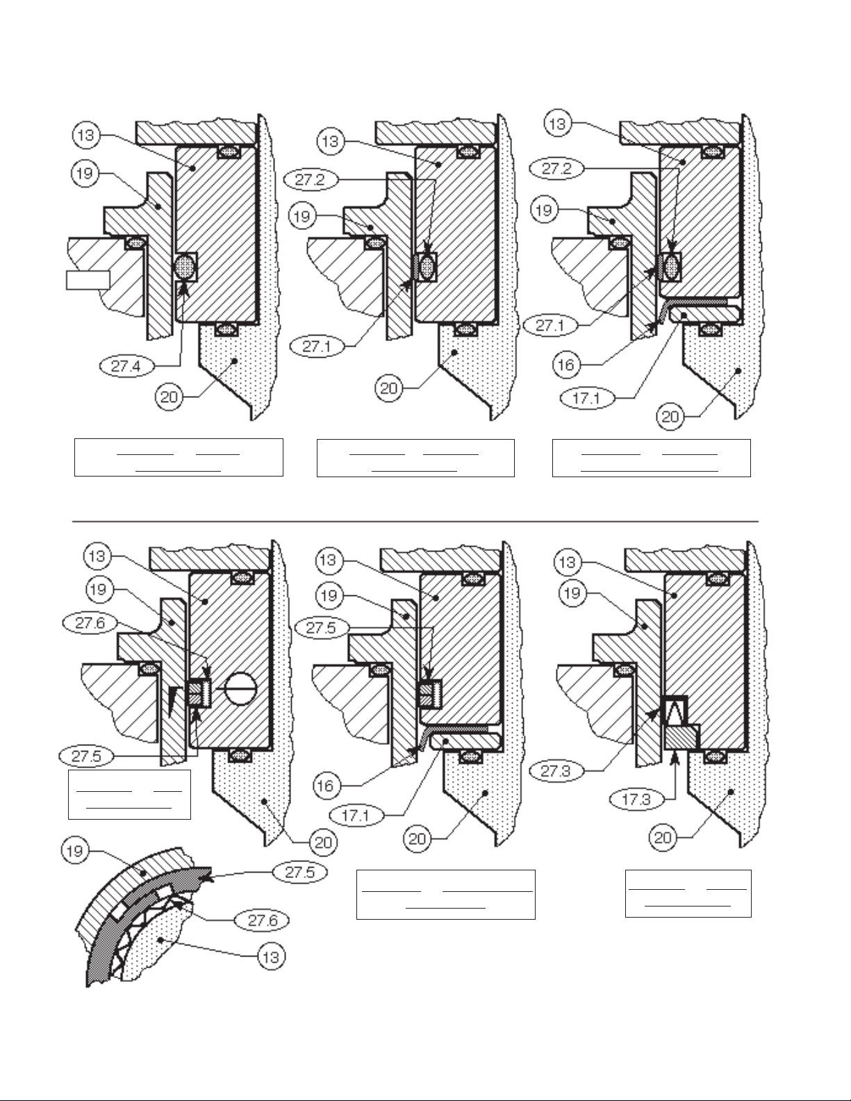
A detailed view of the dynamic side seal parts
is shown in Figure 1 on the next page.
6. Sub-Sections B. through F. are for con struc tions that do NOT include any Opt-81 High
Outlet Pressures with di a phragm support.
These con struc tions are cov ered in SubSec tion G.
IOM-DA4
3
Page 4
Type OR — O-Ring
Dynamic Seal
Type PR — PRA
Dynamic Seal
Type CP— TFE Cap
Dynamic Seal
A
Type CW — TFE Cap
Dynamic Seal + Wiper
Type PW — PRA Dy nam ic
Seal + Wiper
Type UC — U-Cup
Dynamic Seal
SECTION "A"
Figure 1: Dynamic Side Seals
4
IOM-DA4
Page 5
B. Main Valve Disassembly:
12. Remove the ITA by pulling up on the valve
plug (20). Set ITA aside.
WARNING
SYSTEM UNDER PRESSURE. Prior to per form ing any
maintenance, isolate the reg u la tor from the system and
relieve all pressure. Failure to do so could result in personal injury.
1. Shut down system in accordance Section VI.
2. Disconnect the external sensing line, if in stalled.
3. Though it is possible to disassemble the
valve unit while installed in a pipeline, it is
rec om mend ed that maintenance be done in
a shop when possible. The descriptions hereafter will assume shop disassembly. Remove
valve from pipeline.
4. Place the valve unit in a vise with the cover
dome (25) upwards.
5. Loosen the diaphragm fl ange bolts (11) and
nuts (12) uniformly.
6. Place matchmarks on body (23) and cover
dome (25) fl anges. Remove cover dome (25).
7. For composition diaphragm construction, hold
the milled “fl ats” on top of the valve plug (20)
stationary. Loosen and remove the di a phragm
lock nut (7). NOTE: Metal di a phragm con struc-
tions do NOT have a di a phragm lock nut (7).
8. Remove upper diaphragm pressure plate (8).
9. Remove diaphragm(s) (9, 9.1, 9.2, 9.9) and
o-ring upper stem seal (14.1). Examine
diaphragm(s) to determine whether failed;
determine if op er at ing conditions are ex ceed ing pressure, pressure drop or temperature limits.
10. For composition diaphragm construction,
re move lower diaphragm pusher plate (10).
11. Evenly loosen the three cage cap screws (18)
in single revolution increments. Regulator
may con tain a lower piston spring (22); the
ITA should rise as the cage cap screws (18)
are evenly backed out. A down wards holding force should be ap plied to the top of the
piston-guide bearing (13) to pre vent the ITA
from pop ping up as the last threads of the
cage cap screws (18) are backed out.
13. Remove the lower piston spring (22), as ap pli ca ble, from within the body (23).
14. Remove o-ring cage seal (15).
15. If supplied, remove internal sensing drilled
plug (32) using 5/32" (4 mm) Allen wrench.
16. Remove body (23) from vise. Clean all
re us able metal parts according to owner's
pro ce dures.
C. Disassembly of the ITA:
1. Units with Composition Diaphragm(s) (See
Figure 2):
a. Pull the valve plug (20) down wards and
out of the piston-guide bear ing (13) and
out of the cage's (19) bottom, while hold ing the cage (19).
b. Remove the piston-guide bearing (13)
from the upper end of the cage (19).
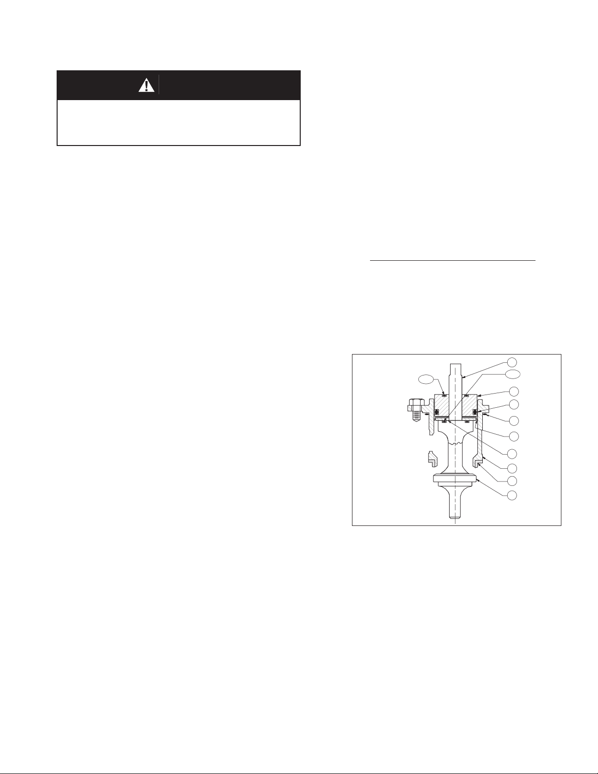
20
14.2
14.3
13
27
15
16
17
19
21
20
Figure 2: Assembled ITA,
Composition Di a phragm Construction
c. Remove o-ring middle stem seal (14.2)
from piston-guide bearing (13).
d. Examine the com po nents (27.1, 27.2,
27.3, 27.4, 27.5, 27.6) of the dy nam ic
side seal (27) mechanism to de ter mine if
sig nifi cant leakage was oc cur ring. If the
dy nam ic side seal (27) shows signs of
sig nifi cant leakage, de ter mine if op er at-
ing con di tions are ex ceed ing pres sure,
pres sure drop, or tem per a ture limits.
Remove dynamic side seal (27) com po-
nents. Special care should be taken when
using “tools” to remove the components
IOM-DA4
5
Page 6
to ensure that no scratches are imparted
to any portion of the piston-guide bearing
(13) groove.
e. Remove wiper seal (16), if supplied, from
within cage (19).
f. Remove wiper washer (17.1) or camber
adjusting washer (17.2), if supplied, from
within cage (19).
g. Remove o-ring lower stem seal (14.3)
from plug (20).
h. Remove seat ring (21); examine for signs
of leakage. If seat ring (21) shows signs of
signifi cant leakage, determine if op er at ing
con di tions of pressure, pressure drop, or
temperature are ex ceed ing limits.
2. Units with Metal Diaphragm(s) (See Fig 3):
a. To disassemble the ITA, hold the lower
part of the valve plug (20) in a bench
vise; do not hold on the machined sur face in the plug's (20) spindle area. (The
spin dle “slides” in the pressed-in-place
lower guide bushing (24) and can not be
al lowed to be marred.)
b. Using a special double-posted spanner
wrench fi tting (to order see NOTE in
Section X, Parts Ordering Information),
turn the piston-guide bear ing (13) CCW
to loos en; pis ton-guide bear ing (13) can
be re moved by hand after loos en ing.
c. Pull the valve plug (20) downwards out
of the piston-guide bearing (13) and out
thru the bottom of the cage (19).
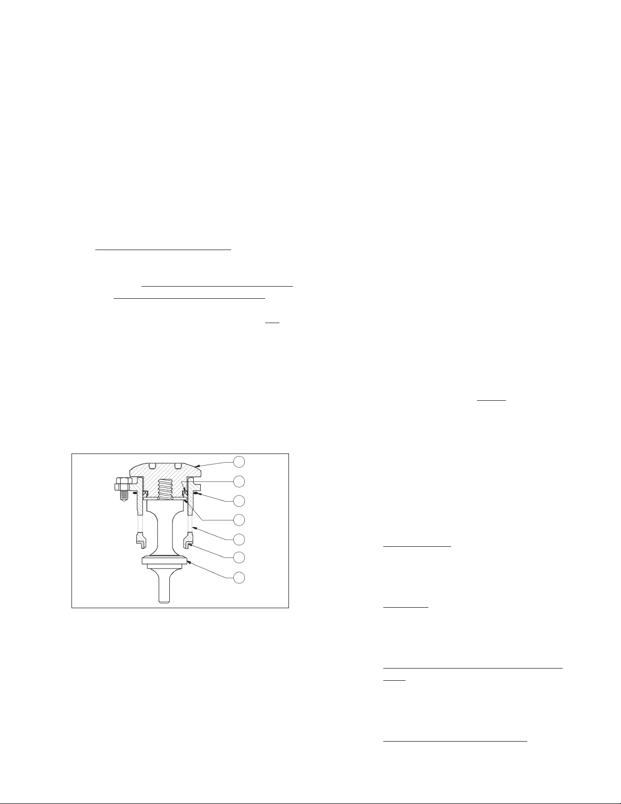
13
27
15
17
19
21
20
Figure 3: Assembled ITA,
Metal Diaphragm Construction
d. Remove the piston-guide bearing (13)
from the upper end of cage (19).
e. Examine the com po nents (27.1, 27.2,
27.3, 27.4, 27.5, 27.6) of the dy nam ic
side seal (27) mechanism to de ter mine
if sig nifi cant leakage was oc cur ring. If the
dy nam ic side seal (27) shows signs of
sig nifi cant leakage, de ter mine if operat-
ing conditions are ex ceed ing pres sure,
pres sure drop, or tem per a ture lim its.
Remove dynamic side seal (27) com po-
nents and discard. Special care should be
taken when using “tools” to remove the
components to ensure that no scratches
are imparted to any portion of the pistonguide bearing (13) groove.
f. Remove wiper seal (16), if supplied, from
within cage (19).
g. Remove wiper washer (17.1) or camber
adjusting washer (17.2), if supplied, from
within cage (19).
h. Remove o-ring lower stem seal (14.3)
from plug (20).
i. Remove seat ring (21); examine for signs
of leakage. If seat ring (21) shows signs of
signifi cant leakage, determine if op er at ing
con di tions of pressure, pressure drop, or
temperature are ex ceed ing limits.
3. Clean all reusable metal parts according to
owner's procedures.
D. Inspection of Parts:
1. After inspection remove from the work area
and dis card the old “soft goods” parts (i.e. orings, di a phragms, seals, gaskets, etc.) after
in spec tion. These parts MUST be re placed
with fac to ry supplied new parts.
2. Inspect the metal parts that will be reused. The
parts should be free of surface con tam i nants,
burrs, oxides, and scale. Rework and clean
parts as necessary. Surface con di tions that
affect the regulator performance are stated
below; replace parts that can not be re worked
or cleaned.
3. QC Requirements:
a. Valve plug (20);
1. 16 rms fi nish on its seating surface
for tight shutoff.
2. No major defects on bottom guide
spin dle.
b. Cage (19);
1. 16 rms fi nish on cylinder bore. No
“ledges” formed due to wear from
moving dynamic side seal (27) or
wiper seal (16).
c. Lower guide bushing (24) (non-re place-
able):
1. 16 rms fi nish on bore.
2. Max 0.015 inch (0.38 mm) clearance
be tween valve plug (20) spindle and
lower guide bushing (24).
d. Internal sensing drilled plug (32);
6
IOM-DA4
Page 7

1. Ensure that bore is minimum 0.125
inch (3.20 mm). Drill out as required.
4. Staging Material for Reassembly.
a. Inspect and clean parts, as necessary,
from the spare parts kit. (See Article VII
.A.4. comments concerning cleaning for
ox y gen service.)
b. Lay out all the regulator parts and check
against the bill of material.
E. Reassembly of the ITA:
“cut” o-ring energizer/seal (27.2). Using thumbs, work the o-ring en er giz er/
seal (27.2) up and into the groove of
Not supplied. Use any
bolt, washers (2) and
nut of same approximate
hole size.
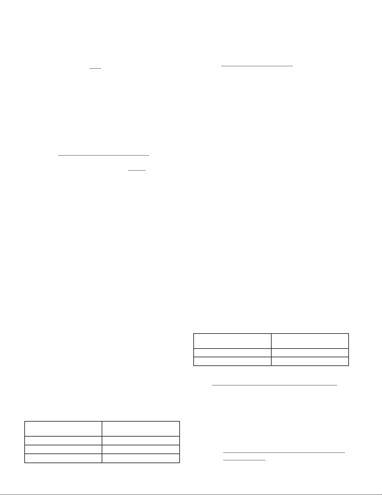
17
19
1. When replacing the optional wiper seal (16),
the replacement wiper seal (16) is “preformed”. It may, however, require reforming.
Under normal circumstances, this step may
not be required. If needed, reform the wiper
seal (16) by press ing the temporary assembly
parts into the cage (19) backwards as shown
in Figure 4. The wiper seal (16) is best left in
this position overnight (minimum of two (2)
hours) prior to re as sem bly.
2. After forming the wiper seal, remove parts
(13, 16, 17) from cage (19) and disassemble
the tem po rary assembly of Step 1. above.
3. Installation of dynamic side seal (27) (See
Figure 1):
a. Type OR:
1. Stretch o-ring seal (27.4) over lower
cir cum fer ence of piston-guide bear ing
(13), tak ing care not to “cut” o-ring
seal (27.4). Using thumbs, work the
o-ring seal (27.4) up and into the
groove of the piston-guide bearing
(13). NOTE: A very slight amount
of fl uid and elas tomer compatible
lu bri cant is rec om mend ed as an
in stal la tion aid.
2. For metal diaphragm construction,
insert cam ber adjusting washer (17.2)
into cage (19) and allow to rest in the
bottom of the cage (19).
3. Position piston-guide bearing (13)
over upper end of cage (19) properly oriented. Using thumbs, evenly
press piston-guide bearing (13) into
the cage (19), ensuring not to “cut”
o-ring seal (27.4). Continue pressing
pis ton-guide bearing (13) until in ap prox i mate fi nal position.
b. Type CP:
1. Stretch o-ring energizer/seal (27.2)
over low er cir cum fer ence of pistonguide bear ing (13), tak ing care not to
16
13
Figure 4: Temporary Assembly Parts
bear ing (13). NOTE: A very slight
amount of fl uid and elas tomer com-
patible lu bri cant is rec om mend ed as
an in stal la tion aid.
2. For metal diaphragm construction, insert cam ber adjusting washer (17.2)
into cage (19) and allow to rest in the
bottom of the cage (19).
3. Position TFE cap seal (27.1) ring with
rectangular cross-section at end of
pis ton-guide bearing (13). Stretch cap
seal (27.1) over lower end of pistonguide bear ing (13) using thumbs to
work the cap seal (27.1) onto the piston-guide bearing (13). DO NOT USE
A TOOL FOR THIS STEP. Con tin ue
pressing cap seal (27.1) up wards towards the groove until the cap seal
(27.1) “snaps” into the groove of the
piston-guide bearing (13).
4. Position piston-guide bearing (13)
over and into upper end of cage (19)
until the cap seal (27.1) edge touches
the upper lip of the cage (19). While
gently applying force to press the
piston-guide bushing (13) into the
cage (19), simultaneously use fi n gers
to lightly press the cap seal (27.1)
inwards into the groove of the pis tonguide bearing (13) until the cap seal
(27.1) “slips into” the cage (19). DO
NOT USE TOOLS, LU BRI CANT, OR
HEAVY FORCE TO EN GAGE THE
CAP SEAL (27.1) INTO THE CAGE
(19). Do not press in wards on the Cap
Seal (27.1) too much or the cap seal
(27.1) may slide out of its groove or
the cap seal (27.1) can be damaged.
IOM-DA4
7
Page 8

c. Type CW:
1. Stretch o-ring energizer/seal (27.2)
over low er cir cum fer ence of pistonguide bear ing (13), tak ing care not
to “cut” o-ring energizer/seal (27.2).
Using thumbs, work the o-ring en er giz er/seal up and into the groove of
the bear ing (13). NOTE: A very
slight amount of fl uid and elas tomer
compatible lu bri cant is rec om mend ed
as an in stal la tion aid.
2. Place wiper washer (17.1) into “cup” of
Wiper Seal (16). Holding these parts
(17.1 & 16) between thumb and forefi nger, in sert into cage (19) at an approximate 45° angled approach with
wiper washer (17.1) on bottom, wiper
seal (16) on top with turned-down lip
of wiper seal (16) en ter ing cage (19)
fi rst. Rotate wiper seal (16) and wiper
washer (17.1) to a level po si tion approximately half way down into cage
(19). Allow wiper washer (17.1) to rest
on bottom of cage (19).
3. Position TFE cap seal (27.1) ring with
rectangular cross-section at end of
pis ton-guide bearing (13). Stretch cap
seal (27.1) over lower end of pistonguide bear ing (13) using thumbs to
work the cap seal (27.1) onto the
bearing (13). DO NOT USE A TOOL
FOR THIS STEP. Con tin ue pressing cap seal (27.1) up wards towards
the groove until the cap seal (27.1)
“snaps” into the groove of the pistonguide bearing (13).
4. Position piston-guide bearing (13)
over and into upper end of cage (19)
until the cap seal (27.1) edge touches
the upper lip of the cage (19). While
gently applying force to press the
piston-guide bushing (13) into the
cage (19), simultaneously use fi n gers
to lightly press the cap seal (27.1)
inwards into the groove of the pis tonguide bearing (13) until the cap seal
(27.1) “slips into” the cage (19). DO
NOT USE TOOLS, LU BRI CANT, OR
HEAVY FORCE TO EN GAGE THE
CAP SEAL (27.1) INTO THE CAGE
(19). Do not press in wards on the Cap
Seal (27.1) too much or the cap seal
(27.1) may slide out of its groove or the
cap seal (27.1) can be damaged.
d. Type PR:
1. Stretch corrugated metal piston ring
en er giz er (27.6) over lower cir cum fer ence of piston-guide bearing (13).
Using thumbs work the energizer
(27.6) into the bearing (13) groove.
2. Spread a piston ring seal (27.5) and
slide over lower circumference of
pis ton-guide bearing (13), taking care
not to “cut” piston ring seal (27.5).
Using thumbs, work the piston ring
seal (27.5) into the groove of the
bearing (13). Repeat this procedure
with a second piston ring seal (27.5).
NOTE: A piston ring as sem bly (PRA)
consists of one metal corrugated
energizer (27.6) and two piston ring
seals (27.5).
3. Position piston-guide bearing (13)
over and into upper end of cage (19)
until the lower piston ring seal (27.5)
touches the upper lip of the cage (19).
While gently applying force to press
the piston-guide bearing (13) into the
cage (19), si mul ta neous ly use fi n gers
to lightly circumferentially press the
fi rst (lower) piston ring seal (27.5) inwards into the piston-guide bearing
(13) groove until the fi rst piston ring
seal (27.5) “slips into” the cage (19).
Repeat for the second piston ring seal
(27.5).
e. Type PW:
1. Place wiper washer (17.1) into “cup”
of Wiper Seal (16). Holding these
parts (17.1 & 16) between thumb and
forefi nger, in sert into cage (19) at an
approximate 45° angled approach
with wiper washer (17.1) on bottom,
wiper seal (16) on top with turneddown lip of wiper seal (16) en ter ing
cage (19) fi rst. Rotate wiper seal (16)
and wiper washer (17.1) to a level
po si tion approximately half way down
into cage (19). Allow wiper washer
(17.1) to rest on bottom of cage (19).
2. Stretch corrugated metal piston ring
en er giz er (27.6) over lower cir cum fer ence of piston-guide bearing (13).
Using thumbs work the energizer
(27.6) into the bearing (13) groove.
3. Spread a piston ring seal (27.5) and
slide over lower circumference of
pis ton-guide bearing (13), taking care
not to “cut” piston ring seal (27.5).
8
IOM-DA4
Page 9

Using thumbs, work the piston ring
seal (27.5) into the groove of the
bearing (13). Repeat this procedure
with a second piston ring seal (27.5).
NOTE: A piston ring as sem bly (PRA)
consists of one metal corrugated
energizer (27.6) and two piston ring
seals (27.5).
4. Position piston-guide bearing (13)
over and into upper end of cage (19)
until the lower piston ring seal (27.5)
touches the upper lip of the cage (19).
While gently applying force to press
the piston-guide bearing (13) into the
cage (19), si mul ta neous ly use fi n gers
to lightly circumferentially press the
fi rst (lower) piston ring seal (27.5)
inwards into the piston-guide bearing
(13) groove until the fi rst piston ring
seal (27.5) “slips into” the cage (19).
Repeat for the second piston ring seal
(27.5).
f. Type UC:
1. Stretch u-cup seal (27.3) over lower
circumference of piston-guide bear ing (13), taking care not to “cut”
u-cup seal (27.3) on the protruding
shelf that is part of the piston-guide
bear ing's (13) groove. Ensure that the
u-cup seal (27.3) is oriented with the
center-open-downwards as shown
in Figure 1, as the u-cup seal (27.3)
depends upon the P1-Inlet Pres sure
to pressure activate the seal for proper
sealing action.
2. Position piston-guide bearing (13)
over and into upper end of cage (19)
until the cap seal (27.1) edge touches
the upper lip of the cage (19). While
gently applying force to press the
piston-guide bearing (13) into the
cage (19), simultaneously use fi ngers
to lightly press the u-cup seal (27.3)
inwards into the groove of the pistonguide bearing (13) until the u-cup seal
(27.3) “slips into” the cage (19). DO
NOT USE TOOLS, LUBRICANT, OR
HEAVY FORCE TO ENGAGE THE
U-CUP SEAL (27.3) INTO THE CAGE
(19).
4. Place properly oriented seat ring (21) onto its
shoul der at the lower end of cage (19).
5. Composition Diaphragm Designs:
a. Place new o-ring lower stem seal (14.3)
into groove of valve plug (20).
b. Insert valve plug (20) upwards through
lower end of cage (19) and through the
center hole in piston-guide bearing (13),
also capturing the camber adjusting
wash er (17.2) or wiper washer (17.1) and
wiper seal (16), if supplied. Hold plug (20)
and cage (19) together.
c. Place an oversized nut or stack of wash-
ers, the same approximate height of the
up per diaphragm pres sure plate (8) and
the lower diaphragm pusher plate (10),
over the upper end of valve plug (20) and
temporarily secure with diaphragm lock
nut (7), manually tightened. Do NOT al low
valve plug (20) to rotate against seat ring
(21) during tightening.
d. This completes ITA preliminary/partial
reassembly.
6. Metal Diaphragm Designs:
a. Insert valve plug (20) upwards through
lower end of cage (19) and through the
center hole of camber adjusting washer
(17.2) or wiper washer (17.1) and wiper
seal (16).
b. Engage valve plug (20) with piston-guide
bearing (13) threads and tighten man u al ly
as far as possible.
c. Place ITA into a vise with leaded jaws and
grasp at a hub location on the valve plug
(20) that is not in the “spindle” zone. (See
Figure 3.)
d. Using a spe cial dou ble-posted span ner
wrench fi t ting (to order see NOTE in Sec-
tion X, Parts Ordering Information), tighten
piston-guide bear ing (13) to the valve plug
(20) with the following torque values. Do
NOT allow valve plug (20) to rotate against
seat ring (21) during tight en ing.
e. This completes ITA reassembly.
F. Main Reassembly:
1. Place body (23) in a vise.
2. Reinstall internal sensing drilled plug (32) with
compatible thread sealant.
3. Insert the lower piston spring (22) into the
body (23), if supplied.
4. Fit the o-ring cage seal (15) into its body (23)
groove.
IOM-DA4
9
Page 10
5. With the ITA held manually in the closed po si tion, insert ITA into body (23).
6. Properly align all three cage bolt (18) holes
as there is only one circumferential location
pos si ble for this align ment. If a lower piston
spring (22) is used, apply downward force to
the top of the cage (19) until the ITA is lowered
suf fi cient ly to engage the cage bolts (18) into
the body (23). Engage all of the cage bolts
(18), then evenly screw in the cage bolts in
one-half revolution increments to pull down
the ITA evenly, taking care NOT TO “AN GLE”
the ITA in the BODY. Torque the cage bolts
(18) to 13-15 ft-lbs (17.6-20.3 N-m).
7. Composition Diaphragm Designs:
a. For the following steps b.– h., the upper
end of valve plug (20) MUST be manually
held up if unit is not supplied with lower
piston spring (22).
b. Remove temporarily installed diaphragm
lock nut (7) and spacers of previous Step
E.5.c. this section.
c. Place new o-ring middle stem seal (14.2)
into groove of piston-guide bearing (13)
upper surface.
d. Position lower diaphragm pusher plate
(10) over upper end of plug (20) with
tongue and groove “groove” on up per
side.
e. Place new o-ring upper stem seal (14.1)
over upper end of valve plug (20).
f. Place diaphragm(s) (9) over end of valve
plug (20). NOTE: For multiple di a phragms
(9) that include TFE material, the TFE
should be on wetted side; for 3-ply TFE
elastomer diaphragm (9), stackup is TFEHK-TFE, beginning with lower wetted
diaphragm (9) fi rst.
g. Place upper diaphragm pressure plate (8)
over upper end of plug (20) with tongue
and groove “ridge” on lower side.
h. Place lubricant on valve plug (20) thread ed
end. Engage diaphragm lock nut (7) with
upper end of valve stem (20) as far as
possible manually.
i. Place a wrench on diaphragm lock nut (7)
and a torque wrench on the upper end
of valve plug (20). Hold torque wrench
sta tion ary and rotate diaphragm lock nut
(7) to the following torque values:
Body Size
in (DN)
1/2" - 1" (15 - 25)
1 1/4" - 2" (32 - 50)
2 1/2" - 4" (65 - 100)
Torque Value
Ft-lbs (N-m)
60 - 70 (81 - 95)
120 - 130 (163 - 176)
180 - 200 (244 - 271)
DO NOT allow valve plug (20) to rotate
against seat ring (21) during tightening.
j. This completes ITA reassembly.
8. Metal Diaphragm Designs:
a. Install new diaphragm gasket (37) onto
body (23) diaphragm fl ange.
b. Position diaphragm(s) (9) onto body's (23)
diaphragm fl ange with bolt holes aligned.
c. Position upper diaphragm pressure plate
(8) onto center top of diaphragm(s) (9)
with rounded side of plate (8) on bottom
next to diaphragm (9).
9. Aligning matchmarks and bolt holes, place
cover dome (25) onto body (23).
10. Reinstall all fl ange bolts (11) and nuts (12)
with nameplate (99) located under one bolt
head. Hand-tighten nuts (12).
NOTE: If a 3-ply diaphragm is being used,
it is important that the diaphragm (9) is “pre formed” – pulled together to remove as much
entrapped air as possible and allow formation
of a diaphragm (9) convolution. Starting with
the body bolts and nuts (11,12) hand tight ened,
“preforming” can be accomplished by any one
of the following techniques:
a. Apply 30 psig (2.1 Barg) pressure to the
valve outlet. OR
Block the valve outlet and apply 30 psig
(2.1 Barg) under the di a phragm through
the 1/4" (DN8) NPT (plugged) external
pres sure sens ing connection on the
valve di a phragm fl ange.
b. Leave pressure on through tightening
of bolt ing (11,12).
11. Evenly tighten the body bolting (11,12) in an
alternating cross pattern in one revolution
increments to the following torque values:
Body Size
in (Dn)
1/2" - 2" (15 - 50) 30 - 35 (41 - 47)
2 1/2" - 4" (65 - 100) 45 - 50 (61 - 69)
Torque Value
Ft-lbs (N-m)
If supplied, remove pressure of previous Step 10.
G. Units with Supported Diaphragm Designs:
1. A supported diaphragm (9) construction is
designated as Opt-81 High Outlet Pressure.
Both upwards and downwards directions
are protected against pressure reversal; i.e.
pres sure on one side of diaphragm (9) with
no pressure on other side of diaphragm (9).
2. Body Sizes 2" (DN50) and Smaller; Com po si tion Diaphragm. (See Figure 5.)
10
IOM-DA4
Page 11
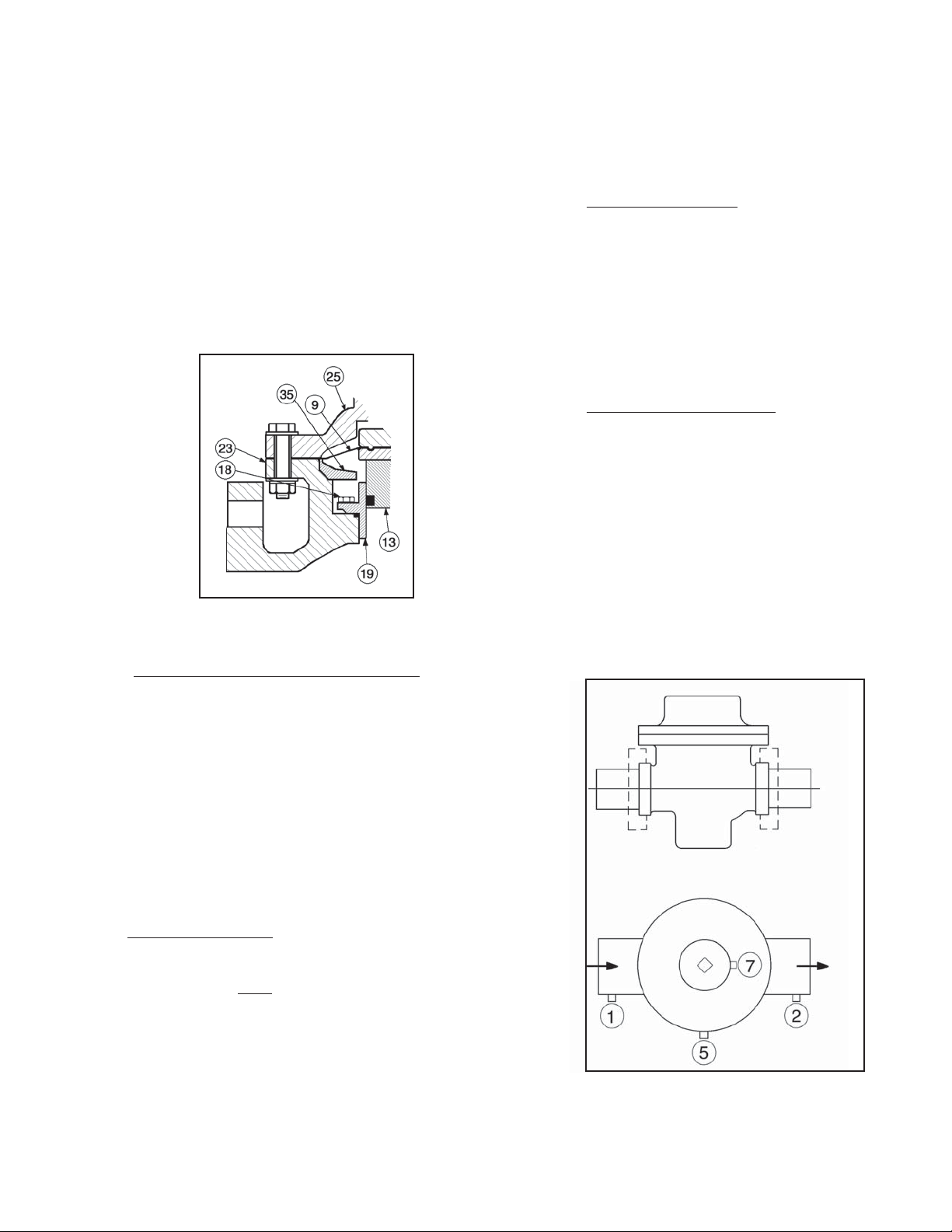
a. Body (23) is specially machined with a
shelf to capture a lower diaphragm sup port ring (35).
b. Cover dome (25) is specially machined to
provide a surface for the upper di a phragm
(9) support. Lower diaphragm support ring
(35) is captured by its location. Upon removal of cover dome (25) and di a phragm
(9), the lower diaphragm support ring (35)
can be lifted upwards and out of the body
(23) cavity.
c. Reinstallation is a reversal of Step b.
above.
DO NOT HYDROSTATICALLY TEST WITH-
OUT COVER DOME PRESSURIZED. NOT
AD HER ING WILL DO PHYSICAL DAMAGE
TO INTERNALS THAT COULD REN DER
THE UNIT IN OP ER A BLE.
2. Inboard Leakage Test.
a. Release all loading pressure in cover
dome.
b. Pressurize inlet to 30 psig (2.1 Barg) with
air, GN
.
2
c. Tube outlet to a beaker of water to ob serve
number of escaping gas bubbles.
Inboard leakage path may be via plug/seat or
dynamic side seal.
3. Pressure Containment Test.
a. Pressurize inlet to 200 psig (13.8 Barg)
and outlet and cover dome to 150 psig
(10.3 Barg) with air or GN
.
2
b. Spray liquid lead detector and check all
ex ter nal leak points; i.e. plugged con nec tions, di a phragm fl ange and di a phragm
bolting.
Figure 5: Opt-81 — Composition Diaphragm
Con struc tion, 2" (DN50) and Smaller
H. Converting Internal/External Sensing:
1. Disassemble the regulator and remove the
diaphragm(s) (9) according to Steps 1-12 in
Part B – Main Regulator Disassembly.
2. To convert from internal to external sensing,
remove the drilled pipe plug (32) and install a
solid pipe plug. Reverse this step for converting from external to internal sensing.
3. Reassemble the regulator according to Part
F – Main Regulator Reassembly.
I. Pressure Testing:
1. If a hydrostatic pressure test is performed,
pressure must be applied to all three of cover
dome (25), inlet and outlet of body at the same
level.
4. Excessive leakage will require disassembly,
examination of sealing elements, correction
of problem, reassembly and retesting.
IOM-DA4
Figure 6: Location of Auxiliary Ports
11
Page 12
VIII. PRESSURE LOADING
SECTION VIII
1. Loading pressure can be supplied using various
schemes. Please reference LOADING SYSTEMS
on web-site for the schematics of these various
schemes, including:
• pressure unloading using BPV
• pressure loading using PRV
• pressure loading using pilot
• pressure loading using I/P transducer
LOADING PRESSURE FOR
MODEL DA4
APPLIED PRESSURES
2. The Model DA4 exhibits a deviation in outlet controlled pressure when the inlet pressure var ies; this
“effect” is identifi ed as ISR – Inverse Sympathetic
Ratio. Its relative pressure effect can be calculated
from the following equation.
ISR FACTOR
BODY SIZE
in (DN)
1/2" - 1" (15 - 25) 3.0
1 1/4" - 1 1/2" (32 - 40) 4.0
2" (50) 2.0
2 1/2" - 4" (65 - 100) 5.4
PISTON SPRING
LOWER PISTON
SPRING RANGE
psig (Barg)
none (none) 0 (0) 0 (0)
2 - 5 (.14 - .34) 3 (.21) 2 (.14)
1 - 2 (.07 - .14) 1 (.07) 1 (.07)
4 - 10 (.28 - 6.9) 6 (.41) 4 (.28)
∆P Piston
Spring
psig (Barg)
ISR – %
LVPS
psig
(Barg)
12
SIZE / ORIENTATION – S/O Factor
Body Size
in (DN)
1/2" - 1" (15 - 25) 1 -1
1 1/4" - 1 1/2" (32 - 40) 2 -2
2" (50) 2.5 -2.5
2 1/2" - 3" (65 - 80) 3 -3
4" (100)
P
= ISR Effect +
LOAD
Compression Effect Spring Preload Orientation Effect
P
= P2 + [ISR x (P1 – P2)] +
Load
Lower Piston Spring + Lower Piston Spring + Body Size
C
Req'd
V
C
x ∆PPiston Spr. + LVPS + S/O
Max
V
Factor
Cover Dome
on Top
Figure 8: Loading Pres sure Formula
Orientation
Cover Dome
on Bottom
4-4
IOM-DA4
Page 13
SECTION IX
IX. TROUBLE SHOOTING GUIDE
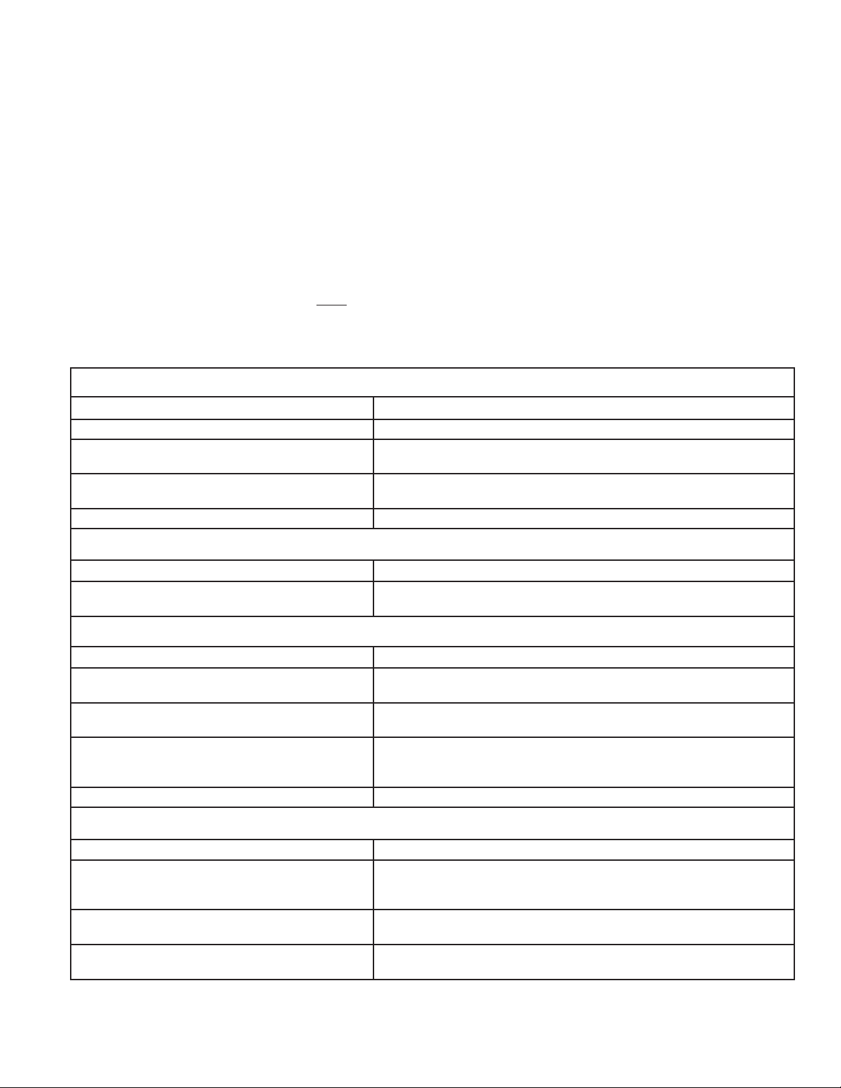
When trouble shooting this regulator there are many possibilities as to what may be causing problems. Many times, the regulator itself is not defective, but one or more of the accessories may be. Sometimes the pro cess may be causing diffi culties.
The key to effi cient trouble shooting is information and communication. The customer should try to be as precise as possible
in their explanation of the problem, as well as their understanding of the application and operating con di tions.
It is imperative the following information be provided by the customer:
• Fluid (with fl uid properties) • Range of outlet pressure
• Range of fl ow rate • Range of fl uid temperature
• Range of inlet pressure • Range of ambient temperature
Pressure readings should be taken at every location where pressure plays a role - i.e., regulator inlet (as close as possible to
inlet port), regulator outlet (as close as possible to outlet port), etc.
Following are some of the more common complaints along with possible causes and remedies.
1. Erratic regulation, instability or hunting.
Possible Causes Remedies
A. Sticking of internal parts. A. Remove internals, clean, and if necessary, replace.
B. Load changes are too quick for system.
C. Oversized regulator.
D. Too much variation in Inlet Pressure - P1. D. Consider use of a pilot for closer Outlet Pressure – P2
B. Convert to external sensing (if necessary) and install an orifi ce or
needle valve in external sensing line.
C. Check actual fl ow conditions; resize regulator for min i mum and maxi-
mum fl ow; if necessary, replace with smaller regulator.
2. Erratic regulation, instability or hunting (liquid service).
Possible Causes Remedies
A. Air trapped under diaphragm. A. Install valve on external sensing port and bleed off air. (Install
regulator upside down to help prevent reoccurrence.
3. Downstream pressure will not reach desired setting.
Possible Causes Remedies
A. Supply pressure is down (confi rm on pressure
gauge.
B. Undersized regulator. B. Check actual fl ow conditions; resize regulator for min i mum and maxi-
C. Pressure loading system pressure restricted. C1. Clean restriction or bleed orifi ces.
D. Faulty loading pressure control device. D. Replace/repair loading pressure control device.
A. Increase supply pressure.
mum fl ow; if necessary, replace with larger regulator.
C2. Clean fi lter(s).
C3. Clean loading pressure control device.
4. Diaphragm continually breaks (steam service regulators).
Possible Causes Remedies
A. Stem seals (14) which protect fl uorocarbon
elastomer in diaphragm assembly may have
deteriorated.
B. Diaphragm nut (7) may not be torqued to
correct value.
C. Diaphragm too stiff causing it to crack. C. Follow proper preforming and air evacuation techniques during
A. Replace with new stem seals (14).
B. Confi rm torque value in accordance with Section VII, F-7-i.
diaphragm installation in accordance with Section VII, F-10.
IOM-DA4
13
Page 14
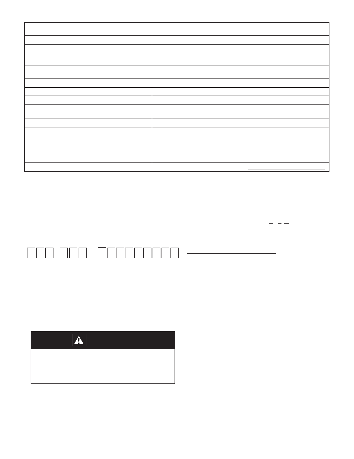
5. Diaphragm continually breaks (all regulators).
Possible Causes Remedies
A. Differential pressure across diaphragm may
have exceeded limits. (See Table 1 in DA4-TB)
A1. Be aware of limits as well as where the various pressures are acting.
Install pressure safety equipment as necessary.
A2. Consider if full diaphragm support, Opt-81, should be added.
6. Leakage at diaphragm fl ange.
Possible Causes Remedies
A. Body bolts not torqued properly. A. Torque to proper value (see Section VII, F-11).
B. Pressures at diaphragm may be too high. B. Consult factory.
7. Leakage across seat.
Possible Causes Remedies
A. Contamination (debris) in regulator. A. Remove internals, clean, and if necessary, replace sealing and seat-
ing
elements. *
B. Oversized regulator; valve plug operates
directly next to seat.
* Seat leakage may be diagnosed when a failure of the dynamic side seal has occurred. Inspect both potential internal leak paths.
B. Check actual fl ow conditions; resize regulator for minimum and maxi-
mum fl ow; if necessary, replace with smaller regulator.
SECTION X
X. ORDERING INFORMATION
NEW REPLACEMENT UNIT vs PARTS "KIT" FOR FIELD REPAIR
To obtain a quotation or place an order, please retrieve the Serial Number and Product Code that was stamped on
the metal name plate and attached to the unit. This information can also be found on the Bill of Material ("BOM").
a parts list that was provided when unit was originally shipped. (Serial Number typically 6 digits). Product Code
typical format as follows: (last digit is alpha character that refl ects revision level for the product).
–
–
7
PARTS "KIT" for FIELD REPAIR:
Contact your local Cashco, Inc., Sales Rep re sen-
NEW REPLACEMENT UNIT:
ta tive with the Serial Number and Product code.
Identify the parts and the quantity required to repair
Contact your local Cashco, Inc., Sales Rep re sen ta tive with the Serial Number and Product code.
the unit from the "BOM" sheet that was provided
when unit was originally shipped.
With this information they can provide a quotation
for a new unit including a complete description,
price and availability.
NOTE: Those part numbers that have a quantity indicated
under "Spare Parts" in column "A” refl ect minimum
parts required for inspection and rebuild, - "Soft
Goods Kit". Those in column “B” include minimum
trim replacement parts needed plus those "Soft
CAUTION
Do not attempt to alter the original construction of any
unit without assistance and approval from the factory. All
purposed changes will require a new name plate with appropriate ratings and new product code to accommodate
the recommended part(s) changes.
Goods" parts from column "A".
If the "BOM" is not available, refer to the crosssectional drawings included in this manual for part
identifi cation and selection.
A Local Sales Representative will provide quotation
for appropriate Kit Number, Price and Availability.
14
NOTE: In addition to ordering repair parts, it is recommended that a special double-posted spanner wrench
fi tting be ordered for use in the main te nance of the ITA. See table on page 15 for part number.
IOM-DA4
Page 15
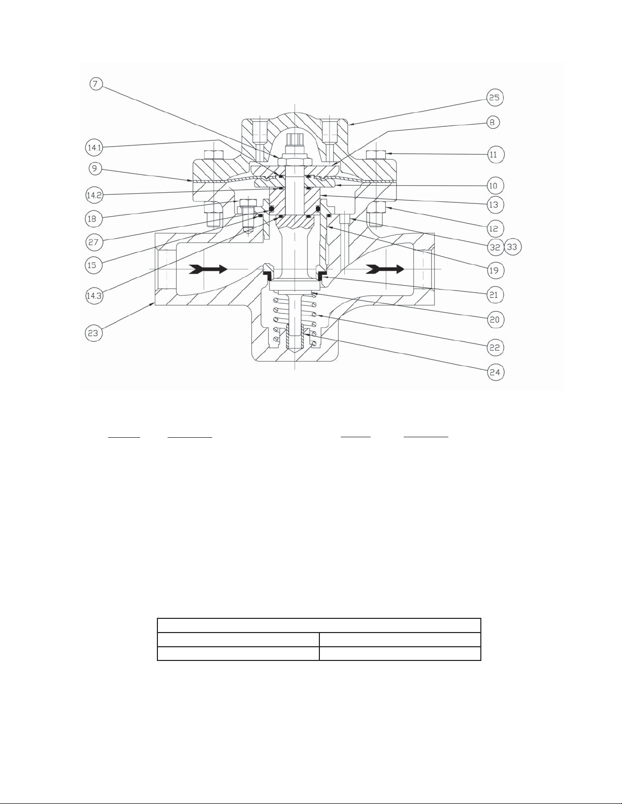
Model DA4
Composition Diaphragm
(without Wiper Seal)
Item No. Description
7 Diaphragm Lock Nut
8 Upper Diaphragm Pressure Plate
9** Diaphragm
10 Lower Diaphragm Pusher Plate
11 Flange Bolts
12 * Flange Bolt Nuts
13 Piston-Guide Bearing
14** Stem Seals
14.1 Upper Stem Seal
14.2 Middle Stem Seal
14.3 Lower Stem Seal
15** Cage Seal
18 Cage Cap Screws
19 Cage
20 Valve Plug
Double-Posted Spanner Wrench Fitting
Body Size Part Number
All A96-75-9-P0459-00
The contents of this publication are presented for informational purposes only, and while every effort has been made to ensure their accuracy, they are not to be
construed as warranties or guarantees, express or implied, regarding the products or services described herein or their use or applicability. We reserve the right to
modify or improve the designs or specifi cations of such product at any time without notice.
Cashco, Inc. does not assume responsibility for the selection, use or maintenance of any product. Responsibility for proper selection, use and maintenance of any
Cashco, Inc. product remains solely with the purchaser.
Item No. Description
21** Seat Ring
22 Lower Piston Spring (if supplied)
23 Body
24 Lower Guide Bushing
25 Cover Dome
26 Tap Plug (Not Shown)
27** Dynamic Side Seal (See Figure 1)
32 Internal Sensing Plug – Solid
(External Sensing Only)
33 Internal Sensing Plug – Drilled
(Internal Sensing Only)
99 Nameplate
* Not required on 2" CS & SST Body Material.
** Recommended Repair Parts.
IOM-DA4
15
Page 16
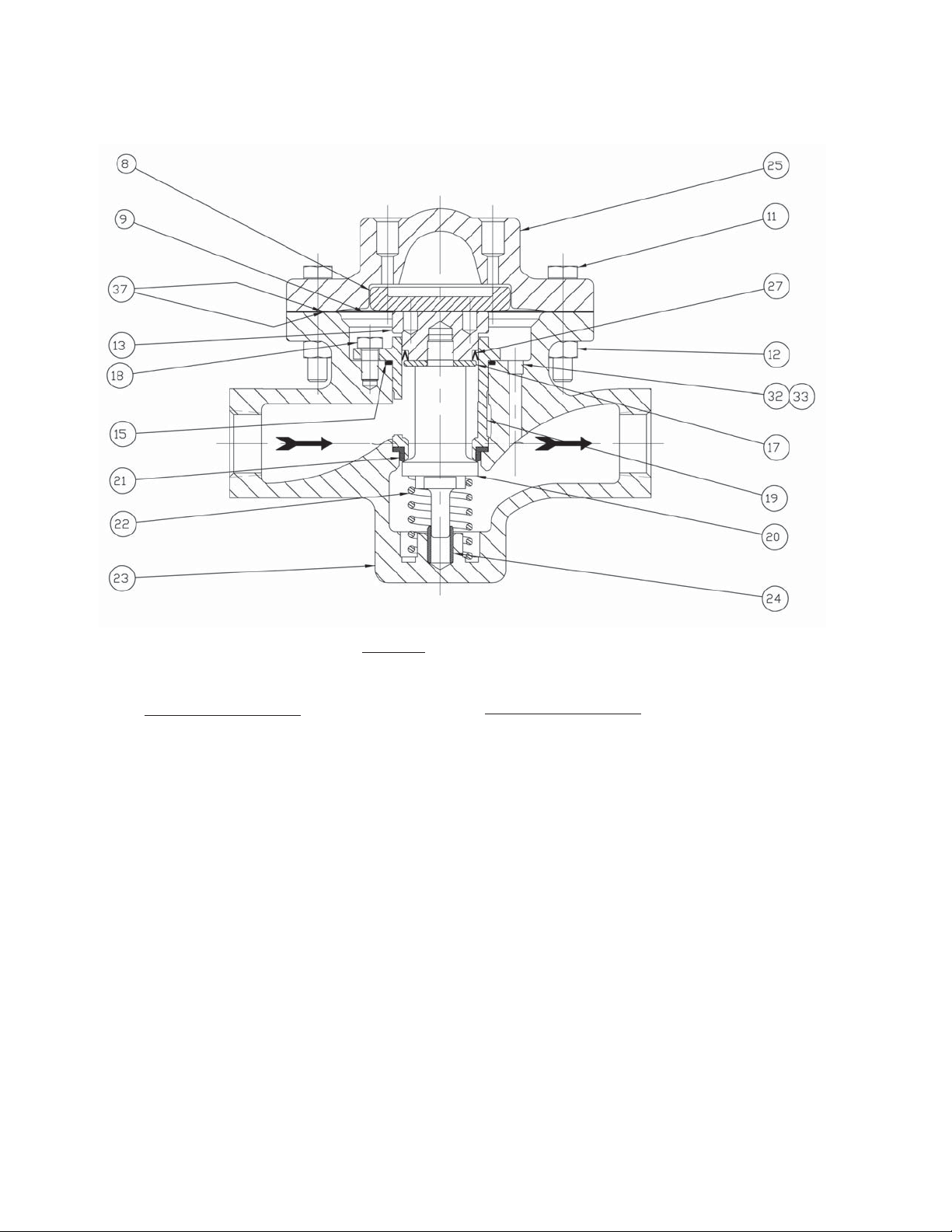
Model DA4
Metal Diaphragm
(with Type UC – U-Cup Dynamic Seal)
Item No. Description
8 Upper Diaphragm Pressure Plate
9** Diaphragm
11 Flange Bolts
12 * Flange Bolt Nuts
13 Piston-Guide Bearing
15** Cage Seal
17 Camber Adjusting Washer
18 Cage Cap Screws
19 Cage
20 Valve Plug
21** Seat Ring
22 Lower Piston Spring
Cashco, Inc.
P.O. Box 6
Ellsworth, KS 67439-0006
PH (785) 472-4461
Fax. # (785) 472-3539
www.cashco.com
email: [email protected]
Printed in U.S.A. DA4-IOM
Cashco GmbH
Handwerkerstrasse 15
15366 Hoppegarten, Germany
PH +49 3342 4243135
Fax. No. +49 3342 4243136
www.cashco.com
Email: [email protected]
Item No. Description
23 Body
24 Lower Guide Bushing
25 Cover Dome
26 Tap Plug (Not Shown)
27** Dynamic Side Seal (See Figure 1)
32 Internal Sensing Plug – Solid
(External Sensing Only)
33 Internal Sensing Plug – Drilled
(Internal Sensing Only)
37** Diaphragm Gasket
99 Nameplate
* Not required on 2" CS & SST Body Material.
** Recommended Repair Parts
Cashco do Brasil, Ltda.
Al.Venus, 340
Indaiatuba - Sao Paulo, Brazil
PH +55 11 99677 7177
Fax. No.
www.cashco.com
Email: [email protected]
 Loading...