

Page 1
INSTALLATION, OPERATION & MAINTENANCE MANUAL (IOM)
IOM-D/DL
12-16
ISO Registered Company
MODELS D and DL
PRESSURE REDUCING REGULATORS
SECTION I
I. DESCRIPTION AND SCOPE
The Model D is a pressure reducing regulator used to control downstream (outlet or P2) pressure. Sizes are 3/8" (DN10),
1/2" (DN15), 3/4" (DN20) and 1" (DN25). With proper trim utilization, the unit is suit able for liquid, gase ous, or steam
serv ice. Refer to Technical Bulletin D-TB for design conditions and se lec tion recommendations.
The Model DL is also a pressure reducing regulator similar to above Model D. Sizes are 1-1/2" (DN40) and 2" (DN50).
(Model DL was formerly a Cashco Model D). Refer to Technical Bulletin DL-TB for design conditions and selection
recommendations.
SECTION II
II. INSTALLATION
Outlet
@ P2
CAUTION
For welded installations, all internal trim parts, seals
and diaphragm(s) must be removed from regulator
body prior to welding into pipeline. The heat of
fusion welding will damage non-metallic parts if
not removed. NOTE: This does not apply to units
equipped with extended pipe nipples.
Supply
@ P1
Model D or DL
Reducing
Regulator
SRV
Bypass
1. An inlet block valve should always be in stalled.
2. If service application is continuous such that
shut down is not readily accomplished, it is recommended that an inlet block valve, outlet block
valve, and a manual bypass valve be installed.
3. Pipe unions should be installed to allow re moval
from piping.
4. An outlet pressure gauge should be located
ap prox i mate ly ten pipe diameters downstream and
within sight.
5. All installations should include a downstream
re lief device if the inlet pressure could exceed the
pres sure rating of any downstream equip ment or the
maximum outlet pressure rating of the unit.
CAUTION
Installation of adequate overpressure pro tec tion
is recommended to pro tect the reg u la tor from
overpressure and all down stream equip ment from
damage in the event of regulator failure.
Blowdown-Drain Blowdown-Drain
(Shaded portion for steam/condensate systems)
Recommended Piping Schematic
For Pressure Reducing Station
6. Clean the piping of all foreign material in clud ing
chips, welding scale, oil, grease and dirt be fore
installing the regulator. Strainers are rec om mend ed.
7. In placing thread sealant on pipe ends prior to
en gage ment, ensure that excess material is
re moved and not allowed to enter the regu la tor upon
startup.
8. Flow Direction: Install so the flow direction match es
the arrow cast on the body.
9. For best performance, install in well drained
hori zon tal pipe, properly trapped, if a steam service
application.
10.A. Basic Regulator - (Refer to Figure 2): Regu la tor
may be rotated around the pipe axis 360o. Recom mended position is with spring cham ber ver ti cal
upwards. Ori ent such that the spring cham ber vent
hole does not collect rainwater or debris.
Page 2

CAUTION
DO NOT HYDROSTATIC TEST THROUGH AN
IN STALLED UNIT; ISOLATE REGU LA TOR FROM
TEST. The upper range spring pressure level listed
on the nameplate or 100 psig (6.9 Barg) minimum
is the rec om mend ed “upper op era tive lim it” for
the sens ing dia phragm (see Sec tion IV. Startup,
Num ber 7.) Higher pres sures could cause in ter nal
dam age. In addition, note on the name plate that the
Inlet and Outlet pres sure and tem pera ture ratings
are at dif fer ent levels.
10.B. Model D Cryogenic Regulator - Option D-5 or D-36
(Refer to Figure 4):
SECTION III
III. PRINCIPLE OF OPERATION
a. Recommended installation is with spring cham-
ber hang ing directly below the body in a vertical
down wards ori en ta tion. Al lows water to drain;
i.e. rainwater, etcet era.
b. Recommend inert purge gas to spring cham ber
through vent hole and out drain hole.
11. Regulators are not to be di rect bur ied under ground.
12. For insulated piping systems, rec om men da tion is to
not insulate regulator.
13. Spring Chamber Vent Tap - Option D-25 or DL25: Pipe spring chamber vent opening to remote
lo ca tion. Orient so as not to take on rainwater.
1. Movement occurs as pressure variations register
on the diaphragm. The registering pressure is the
outlet, P2, or downstream pressure. The range
spring or loading pressure (Opt.-20) op pos es
di a phragm movement. As outlet pressure drops,
IV. STARTUP
1. Start with the block valves closed. A bypass valve
may be used to maintain outlet pres sure in the
downstream sys tem without chang ing the fol low ing
steps.
2. Relax the range spring by turning the ad just ing screw
counter clockwise (CCW) a min i mum of three (3) full
revolutions or reduce loading pressure (Opt.-20).
This re duc es the outlet (down stream) pres sure set
point.
3. If it is a “hot” piping system, and equipped with a
bypass valve, slowly open the bypass valve to preheat the system piping and to allow slow ex pan sion
of the piping. Ensure proper steam trap operation
if installed. Close ly monitor outlet (down stream)
pres sure via gauge to en sure not over-pres sur iz ing.
NOTE: If no bypass valve is installed, extra caution
should be used in start ing up a cold system; i.e. do
ev ery thing slow ly.
4. Crack open the outlet (downstream) block valve.
5. Slowly open the inlet (upstream) block valve
ob serv ing the outlet (downstream) pressure gauge.
Determine if the reg u la tor is flowing. If not, slowly
rotate the regulator adjusting screw (6) clock wise
(CW) or increase loading pressure (Opt.-20) until
flow begins.
2
the range spring or loading pressure pushes
the dia phragm down, opening the port; as outlet
pres sure in creas es, the diaphragm push es up and
the port opening closes.
2. A complete diaphragm failure will cause the
reg u la tor to fail open.
SECTION IV
6. Continue to slowly open the inlet (upstream) block
valve until fully open.
7. Continue to slowly open the outlet (downstream)
block valve, especially when the downstream pip ing
system isn't pressurized. If the outlet (down stream)
pressure exceeds the desired pres sure, close the
block valve and go to Step 2, then return to Step 4.
8. When flow is established steady enough that the
outlet (downstream) block valve is fully open, begin
to slowly close the bypass valve if installed.
9. Develop system flow to a level near its expected
normal rate, and reset the regulator set point by
turning the adjusting screw (6) CW to increase outlet
pressure, or CCW to reduce outlet pressure.
10. Reduce system flow to a minimum level and ob serve
set point. Outlet pressure will rise from the set point
of Step 9. The maximum rise in outlet pressure on
decreasing flow should not exceed the stated upper
limit of the range spring by greater than 10%; i.e. 1040 psig (.69 - 2.8 Barg) range spring, at low flow the
outlet pres sure should not exceed 44 psig (3 Barg),
if it does, consult factory.
IOM-D/DL
Page 3
V. SHUTDOWN
1. On systems with a bypass valve, and where sys tem
pressure is to be maintained as the reg u la tor is
shut down, slowly open the bypass valve while
reducing the loading pressure (Opt.-20) and slowly
closing the inlet (up stream) block valve. When all
loading pressure is relieved, fully close the inlet
(upstream) block valve. (When on bypass, the
system pressure must be constantly observed and
manually reg u lat ed.) Close the outlet (down stream)
block valve.
SECTION V
CAUTION
Do not walk away and leave a bypassed reg u la tor
unattended!
2. If the regulator and system are to both be shut down,
remove all loading pressure while slowly closing
the inlet (upstream) block valve. Close the outlet
(downstream) valve only if reg u la tor removal is
required.
SECTION VI
VI. MAINTENANCE
A. General:
WARNING
SYSTEM UNDER PRESSURE. Prior to per form ing
any maintenance, isolate the regulator from the
system and relieve all pres sure. Failure to do so
could result in personal injury.
1. Maintenance procedures hereinafter are based
upon re mov al of the regulator unit from the
pipeline where in stalled.
2. Owner should refer to owner's procedures for
re mov al, handling, cleaning and disposal of
nonreusable parts, i.e. gaskets, etc.
3. Refer to Figure 2 for basic regulator. Refer to
Figure 4 for cryogenic regu la tor. For blow-ups
of Option-4 Stabilizer, refer to Figure 3.
B. Diaphragm Replacement:
3. Draw or embed a match mark between body
casting (1) and spring chamber casting (2)
loading chamber (33) along flanged area.
4. Remove all diaphragm nuts (9) and bolts (8).
5. Remove spring chamber (2), (loading chamber
33),range spring (14), spring button (4),
pressure plate (3) and diaphragm(s) (12).
NOTE: Refer to the quan tity of diaphragms
(12) in cor po rat ed per the bill of materials listing.
Depending on outlet pres sure level, multiple
metal diaph ragms may be “stacked”.
6. Remove pusher plate (11) and inspect for a
fit which limits its travel to a vertical direction.
Wear will show as ex ces sive wobble in push er
plate (11). If apparent, recommend trim removal
and inspection; go to Sub-Sec tion C fol low ing.
Re in stall pusher plate (11).
7. Inspect pressure plate (3) to ensure no
de for ma tion due to over-pressurization. If
de formed, replace.
WARNING
SPRING UNDER COMPRESSION. Prior to removing
flange bolts, relieve spring com pres sion by backing
out the ad just ing screw. Failure to do so may result
in flying parts that could cause personal injury.
1. Securely install the body (1) in a vise with
the spring chamber (2) loading chamber (33)
directed upwards.
2. Relax range spring (14) by turning adjusting
screw (6) CCW until removed from spring
cham ber (2). NOTE: If the D-3 Option
hand wheel is utilized, the adjusting screw (6)
and locknut (7) are re placed respectively by
hand wheel adjusting screw (20) and locking
lever (21). Refer to Figure 1.
IOM-D/DL
8. Clean body (1) and diaphragm flange. NOTE:
On regulators originally supplied as “ox y gen
clean”, Option D-5, D-36, D-55, or DL-55, maintenance must include a level of clean li ness
equal to Cashco cleaning standard #S-1134.
On reg u la tors originally supplied as “cleaned for
Phar ma ceu ti cal and Food ap pli ca tions” Op tion
D-37 or D-37S, main te nance must in clude a
level of cleanliness equal to Cashco cleaning
stan dard #S-1576.
9. Place diaphragm gasket (13) on body (1) flange.
Position diaphragm(s) (12) into place. Vi su al ly
center pres
(12), and set range spring (14) onto retainer hub
of pressure plate (3). (Opt.-20 does not utilize
spring skip to step 11.) NOTE: No dia phragm
gasket (13) for com po si tion dia phragm.
sure plate (3) onto diaphragm(s)
3
Page 4

10. Place multi-purpose, high temperature grease
into de pres sion of spring button (4) where
ad just ing screw bears. Set spring button (4)
onto range spring (14); ensure spring button (4)
is laying flat.
11. Aligning the matchmarks, place spring cham ber
(2) over the above stacked parts. Install all
bolts (8) and nuts (9) by hand tightening.
Mechanically tighten bolting (8 & 9) in a cross
pattern that allows spring cham ber (2) to be
pulled down evenly. Rec om mended torque
values are as follows:
6. Clean debris from within body (1) cavity. Clean
parts to be reused.
NOTE: On regulators originally supplied as
“oxygen clean”, Option D-5 , D-36, D-55, or
DL-55, maintenance must include a level
of clean li ness equal to Cashco cleaning
stan dard #S-1134. On regulators origi nally
sup plied as “cleaned for Phar ma ceu ti cal and
Food applications”, Option D-37 or D-37S,
main te nance must include a level of clean li ness
equal to Cashco clean ing standard #S-1576.
Contact factory for details.
Model
D
DL
Regulator
Size
3/8" thru 1"
(DN10 thru 25)
1-1/2" (DN40) 7/16"-20
2" (DN50) 1/2"-20
Bolt
Size
5/16"-24
Metal
Diaphragm
20-24 Ft-Lbs
(27-32 N-m)
32-36 Ft-Lbs
(43-49 N-m)
42-48 Ft-Lbs
(57-65 N-m)
NOTE: Never replace bolting (8 & 9) with just any
bolting if lost. Bolt heads and nuts are marked
with specification identification mark ings. Use only
proper grades as replacements.
12. Reinstall adjusting screw (6) with locknut (7).
13. Spray liquid leak detector around bolting (8 &
9) and body (1) and spring chamber (2) flang es
and test for leak age. En sure that an outlet
pressure is main tained during this leak test of
at least mid-range spring level; i.e. 10-40 psig
(.69 - 2.8 Barg) range spring, 25 psig (1.7 Barg)
test pressure mini mum.
C. Trim Replacement:
1. Install body (1) in a vise with the body cap (5)
on top and the body (1) flange down wards.
2. Loosen and remove body cap (5).
3. Remove piston spring (17), piston (15), cyl in der
(16) and pusher plate (11). For Opt.-20 do not
remove pusher plate (11). Inspect parts for
excessive wear, espe cially at seat sur fac es.
Re place if worn, nicked or de pressed. (Valves
equipped with Opt-4 Sta bi liz er will have the
u-cup stabilizer seal (32) re moved when the
piston (15) is removed from body (1). Re move
stabilizer seal (32), if installed).
4. Remove the cylinder gasket (18) and clean
con tact ing surface of body (1).
5. Clean flat mating surfaces of body (1) to body
cap (5) shoulder.
Comp.
Diaphragm
16-20 Ft-Lbs
(22-27 N-m)
28-32 Ft-Lbs
(38-43 N-m)
32-36 Ft-Lbs
(43-49 N-m)
7. Reinstall the pusher plate (11). Ensure prop er
position of flat surface being down wards.
Ensure centered.
8. Reinstall a new cyl in der gasket (18). Press firmly
and evenly into place using the cyl in der (16).
Do not use a “homemade” cyl in der gas ket. Pipe
seal ant may be lightly coated to cylinder gasket
(18) surfaces prior to in stal la tion, ex cept when
utilized as Item 6 above.
9. Reinstall the cyl in der (16) con cen tri cally with in
the body cap (5) opening.
10. If supplied with Opt-4 Stabilizer, install new
stabilizer seal (32) properly oriented onto piston
(15). See Figure 4.
11. Slide the piston (15), including sta bi liz er seal
(32) if supplied, slowly into place, as sur ing that
the piston (15) post slides into the female groove
of the pusher plate (11). Use thumbs to ease
stabilizer seal (32) into cyl in der (16).
into
12. Place piston spring (17)
piston (15) cav i ty.
13. Use pipe thread sealant applied to the body cap
(5) threads. Thread body cap (5) into body (1).
For all sizes of the Ductile Iron and SST body
caps -impact until body cap (5) is metal to metal
against body (1) at the body cap (5) shoulder.
For 3/8" & 1/2" size with bronze body cap -
tighten cap to between 70 - 80 Ft-Lbs torque.
For 3/4" & 1" size with bronze body cap -
tighten cap to between 125-150 Ft-Lbs.
14. Bench test unit for suitable operation. NOTE:
Regulators are not tight shutoff devices. Even if
pressure builds up be yond set point, a regulator
may or may not de velop bubble tight shutoff. In
general, tighter shutoff can be expected with
com po si tion seat.
15. Spray liquid leak detector around body cap (5)
and body (1) for test for leakage. Test pres sure
should be a min i mum of 100 psig (6.9 Barg) at
4
IOM-D/DL
Page 5
the inlet. Outlet should be tested to upper value
of range spring (14) with a 100 psig (6.9 Barg)
minimum.
NOTE: When piston (15) assemblies are
used with comp seats, Cashco, Inc. does not
rec om mend attempting to remove the comp seat.
If composition seat is dam aged, re place entire
pis ton assembly.
SECTION VII
VII. TROUBLE SHOOTING GUIDE
1. Erratic operation; chattering.
Possible Causes Remedies
A. Oversized regulator. A1. Check actual flow conditions, resize regulator for minimum and maximum flow.
A2. Decrease regulator pressure drop; decrease inlet pressure by placing a throttling orifice
in inlet piping union; 2-stage pressure drop by using with another regulator in series.
A3. Install next step higher range spring. Contact factory.
A4. Before replacing regulator, contact factory.
B. Inadequate rangeability (regulator full capacity
approximately 50% utilized).
C. Worn piston/cylinder; inadequate guiding. C. Replace trim.
D. Weakened/broken piston spring. D. Replace piston spring. Determine if corrosion is causing the failure; if so, then consider
E. Flow induced instability. E. Replace piston with piston that includes Opt-4 Stabilizer seal.
B1. Decrease regulator pressure drop; decrease inlet pressure by placing a throttling orifice
in inlet piping union; 2-stage pressure drop by using with another regulator in series.
B2. Install next step higher range spring. Contact factory.
alternate trims.
2. Downstream pressure will not reach desired setting.
Possible Causes Remedies
A. Regulator undersized. A1. Confirm by opening bypass valve together with regulator.
A2. Check actual flow conditions, resize regulator; if regulator has inadequate capacity,
replace with larger unit.
B. Plugged trim. B. Remove trim and check for plugged holes in cylinder.
C. Incorrect range spring (screwing in CW of ad justing screw does not allow bringing pressure
level up to proper level).
D. Too much proportional band (droop). D1. Review P.B. (droop) expected.
E. Restricted diaphragm movement. E. Ensure no moisture in spring chamber at temperatures below freeze point. Ensure no
C. Replace range spring with proper higher range. Contact factory.
D2. Contact factory.
dust or debris entering vent opening. If rainwater or debris can enter, re-orient spring
chamber.
3. Leakage through the spring chamber vent hole.
Possible Causes Remedies
A. Normal-life diaphragm failure. A. Replace diaphragm.
B. Abnormal short-life diaphragm failure. B1. Can be caused by excessive chattering. See No. 1. to remedy chatter.
B2. Can be caused by corrosive action. Consider alternate diaphragm material.
B3. For composition diaphragms, ensure not subjecting to over-temperature conditions.
B4. Downstream (outlet) pressure buildup occurring that overstresses diaphragms. Relocate
regulator or protect with safety relief valve.
IOM-D/DL
5
Page 6
4. Excessive pressure downstream.
Possible Causes Remedies
A. Regulator not closing tightly. A. Inspect the seating. Clean and lap metal seat surfaces; replace if lapping does not rem-
B. Downstream block. B. Check system; isolate (block) flow at regulator inlet - not outlet. Relocate regulator if
C. No pressure relief protection. C. Install safety relief valve, or rupture disc.
D. Restricted diaphragm movement. D. Ensure no moisture in spring chamber at temperatures below freeze point. Ensure no
5. Sluggish operation.
Possible Causes Remedies
A. Plugged spring chamber vent.
B. Plugged piston balance port.
C. Fluid too viscous. C. Heat fluid. Contact factory.
edy. If composition seats are depressed, nicked or embedded with debris, replace trim.
necessary..
dust or debris entering vent opening. If rainwater or debris can enter, re-orient spring
chamber.
A.
Clean vent opening.
B.
Remove trim and clean balance port.
SECTION VIII
VIII. ORDERING INFORMATION
NEW REPLACEMENT UNIT vs PARTS "KIT" FOR FIELD REPAIR
To obtain a quotation or place an order, please retrieve the Serial Number and Product Code that was stamped
on the metal name plate and attached to the unit. This information can also be found on the Bill of Material
("BOM"), a parts list that was provided when unit was originally shipped. (Serial Number typically 6 digits).
Product Code typical format as follows: (last digit is alpha character that reflects revision level for the product).
–
NEW REPLACEMENT UNIT:
Contact your local Cashco, Inc., Sales Rep re sen ta tive with the Serial Number and Product code.
With this information they can provide a quotation
for a new unit including a complete description,
price and availability.
–
7
PARTS "KIT" for FIELD REPAIR:
Contact your local Cashco, Inc., Sales Rep re sen ta tive with the Serial Number and Product code.
Identify the parts and the quantity required to repair
the unit from the "BOM" sheet that was provided
when unit was originally shipped.
NOTE: Those part numbers that have a quantity indicated
under "Spare Parts" in column "A” reflect minimum
parts required for inspection and rebuild, - "Soft
CAUTION
Do not attempt to alter the original construction
of any unit without assistance and approval from
the factory. All purposed changes will require a
new name plate with appropriate ratings and new
product code to accommodate the recommended
part(s) changes.
Goods Kit". Those in column “B” include minimum
trim replacement parts needed plus those "Soft
Goods" parts from column "A".
If the "BOM" is not available, refer to the crosssectional drawings included in this manual for part
identification and selection.
A Local Sales Representative will provide quotation
for appropriate Kit Number, Price and Availability.
The contents of this publication are presented for informational purposes only, and while every effort has been made to ensure their accuracy, they are not to be
construed as warranties or guarantees, express or implied, regarding the products or services described herein or their use or applicability. We reserve the right to
modify or improve the designs or specifications of such product at any time without notice.
Cashco, Inc. does not assume responsibility for the selection, use or maintenance of any product. Responsibility for proper selection, use and maintenance of any
Cashco, Inc. product remains solely with the purchaser.
6
IOM-D/DL
Page 7
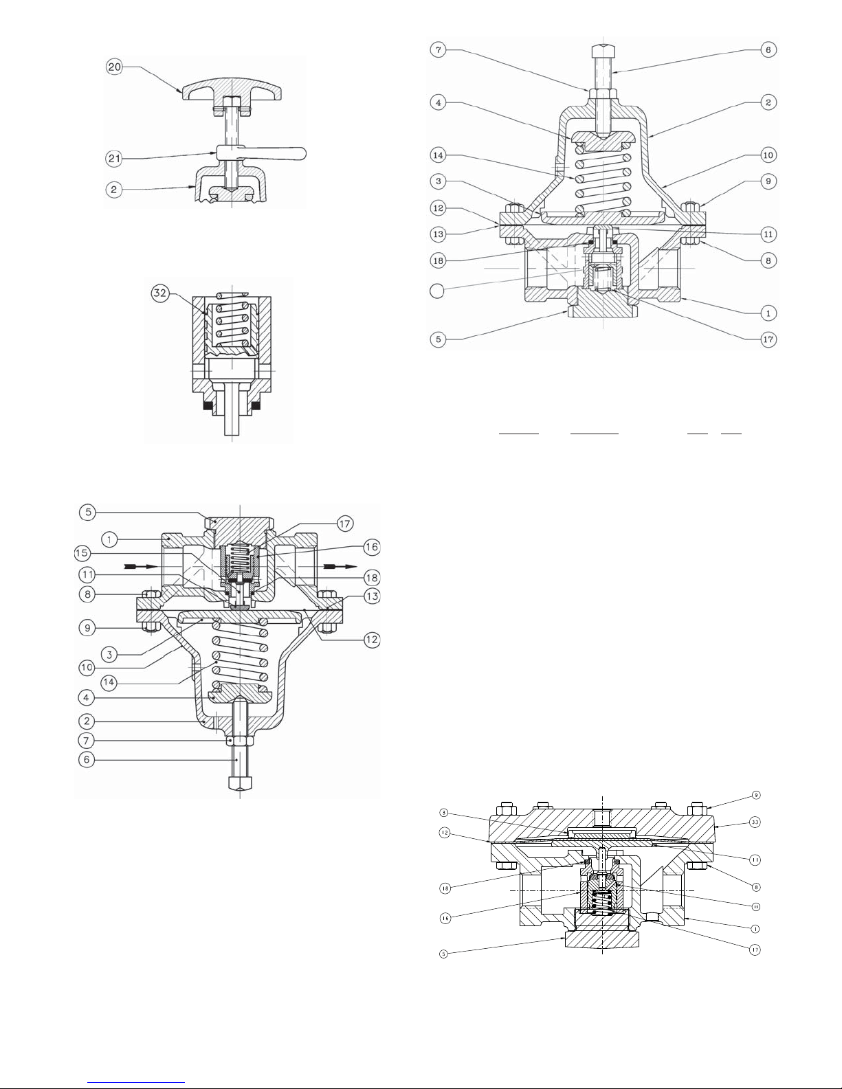
Figure 1: Option D-3 or DL-3
Handwheel and Locking Lever
Figure 3: Option-4 - Stabilizer
NOTE: Mount in horizontal line
with adjusting screw down (as
shown).
16
Figure 2: Basic Model D - Comp Diaphragm
Repair Parts
Item No. Description Kit A Kit B
1 Body
2 Spring Chamber
3 Pressure Plate
4 Spring Button
5 Body Cap
6 Adjusting Screw
7 Nut (hex Jam)
8 Cap Screw (Flange Bolting)
9 Nut (Hex) (Flange Bolting)
10 Name Plate
11 Pusher Plate
12 Diaphragm
13 Diaphragm Gasket
14 Range Spring
15 Piston
16 Cylinder
17 Piston Spring
18 Cylinder Gasket
20 Handwheel Assembly
21 Handwheel Locking Lever
32 Stabilizer Seal
33 Loading Chamber
Not Shown:
27 Gauge
28 Bushing
1
NOT included in kits - must order additionally.
1
**
**
*
**
*
**
**
**
*
**
*
**
Figure 4: Option D-5 or D-36 Cryogenic Model D
Metal Diaphragm
IOM-D/DL
Figure 5: Option-20 - Pressure Loaded
7
Page 8
ATEX 94/9/EC: Explosive Atmospheres and Cashco Inc. Regulators
NOTICE
Only for Product Codes wherein hazard
category ATEX has been selected.
These valves satisfy the safety conditions according to EN 13463-1 and EN 13463-5 for equipment group IIG 2 c.
Caution: Because the actual maximum temperature depends not on the equipment itself, but upon the fluid temperature, a
single temperature class or temperature cannot be marked by the manufacturer.
Specific Precaution to Installer: Electrical grounding of valve must occur to minimize risk of effective electrical discharges.
Specific Precaution to Installer: Atmosphere vent holes should be plugged to further minimize the risk of explosion.
Specific Precaution to Maintenance: The Valve Body/ Housing must be regularly cleaned to prevent buildup of dust deposits.
Specific Precaution to Maintenance: Conduct periodic Continuity Check between Valve Body/ Housing and Tank to minimize
risk of electrical discharges.
Attention: When repairing or altering explosion-protected equipment, national regulations must be adhered to. For maintenance
and repairs involving parts, use only manufacturer's original parts.
ATEX requires that all components and equipment be evaluated. Cashco pressure regulators are considered components.
Based on the ATEX Directive, Cashco considers the location where the pressure regulators are installed to be classified
Equipment-group II, Category 3 because flammable gases would only be present for a short period of time in the event of a leak.
It is possible that the location could be classified Equipment-group II, Category 2 if a leak is likely to occur. Please note that the
system owner, not Cashco, is responsible for determining the classification of a particular installation.
Product Assessment
Cashco performed a conformity assessment and risk analysis of its pressure regulator and control valve models and their
common options, with respect to the Essential Health and Safety Requirements in Annex II of the ATEX directive. The details
of the assessment in terms of the individual Essential Health and Safety Requirements, are listed in Table 1. Table 2 lists all of
the models and options that were evaluated and along with their evaluation.
Models and options not listed in Table 2 should be assumed to not have been evaluated and therefore should not be selected
for use in a potentially explosive environment until they have been evaluated.
Standard default options for each listed model were evaluated even if they were not explicitly listed as a separate option in the
table. Not all options listed in the tables are available to all models listed in the tables. Individual TB’s must be referenced for
actual options.
When specifying a regulator that is to be used in a potentially explosive environment one must review the evaluations in Table 1
and 2 for the specific model and each and every option that is being specified, in order to determine the complete assessment
for the unit.
A summary of the models and options found to have an impact on ATEX assessment due to potential ignition sources or other
concerns from the ATEX Essential Health and Safety Requirements, are listed below.
1. The plastic knob used as standard on some models, (P1, P2, P3, P4, P5, P7, 3381, 4381, 1171, and 2171) is a
potential ignition source due to static electricity. To demonstrate otherwise, the knob must be tested to determine
if a transferred charge is below the acceptable values in IEC 60079-0 Section 26.14 (See items 25, 27, and 28 in
Appendix A). Until the plastic knob has been shown to be acceptable, then either the metal knob option, or a preset
outlet pressure option is required to eliminate this ignition source (See items 45 and 64 in Tables).
2. The pressure gauges offered as options on a few of the regulator models (DA’s, P1-7, D, 764, 521), use a plastic
polycarbonate window that is a potential ignition source due to static electricity. To demonstrate that the gauges are
not a potential source of ignition, the gauges would need to be tested to determine if a transferred charge is below
8
IOM-D/DL
Page 9

indicating the gauge is compliant with the ATEX Directive (See items 26, 27, and 28 in Appendix A). Until compliance
is determined, regulators should not be ordered with pressure gauges for use in potentially explosive environments.
3. Tied diaphragm regulators with outlet ranges greater than 100 psig should be preset to minimize the risk that improper
operation might lead to an outboard leak and a potentially explosive atmosphere (See item 6 in Table 1).
4. Regulators must be ordered with the non-relieving option (instead of the self-relieving option) if the process gas they are
to be used with is hazardous (flammable, toxic, etc.). The self-relieving option vents process gas through the regulator
cap directly into the atmosphere while the non-relieving option does not. Using regulator with the self- relieving option
in a flammable gas system could create an explosive atmosphere in the vicinity of the regulator.
5. Regulators with customer supplied parts are to be assumed to not have been evaluated with regard to ATEX and thus
are not to be used in a potentially explosive environment unless a documented evaluation for the specific customer
supplied parts in question has been made. Refer to Table 1 for all models and options that have been evaluated.
Product Usage
A summary of ATEX related usage issues that were found in the assessment are listed below.
1. Pressure regulators and control valves must be grounded (earthed) to prevent static charge build-up due to the flowing
media. The regulator can be grounded through any mounting holes on the body with metal to metal contact or the
system piping can be grounded and electrical continuity verified through the body metal seal connections. Grounding
of the regulator should follow the same requirements for the piping system. Also see item 30 in Table 1.
2. The system designer and users must take precautions to prevent rapid system pressurization which may raise surface
temperatures of system components and tubing due to adiabatic compression of the system gas.
3. Heating systems installed by the user could possibly increase the surface temperature and must be evaluated by the
user for compliance with the ATEX Directive. User installation of heating systems applied to the regulator body or
system piping that affects the surface temperature of the pressure regulator is outside the scope of this declaration and
is the responsibility of the user.
4. The Joule-Thomson effect may cause process gases to rise in temperature as they expand going through a regulator.
This could raise the external surface temperature of the regulator body and downstream piping creating a potential
source of ignition. Whether the Joule-Thomson effect leads to heating or cooling of the process gas depends on
the process gas and the inlet and outlet pressures. The system designer is responsible for determining whether the
process gas temperature may rise under any operating conditions. If a process gas temperature rise is possible under
operating conditions, then the system designer must investigate whether the regulator body and downstream piping
may increase in temperature enough to create a potential source of ignition.
The process gas expansion is typically modeled as a constant enthalpy throttling process for determining the temperature change.
A Mollier diagram (Pressure – Enthalpy diagram with constant temperature, density, & entropy contours) or a Temperature –
Entropy diagram with constant enthalpy lines, for the process gas, can be used to determine the temperature change. Helium
and hydrogen are two gases that typically increase in temperature when expanding across a regulator. Other gases may
increase in temperature at sufficiently high pressures.
Product Declaration
If the above issues are addressed by selecting options that do not have potential sources of ignition, avoiding options that
have not been assessed, and by taking the proper usage issue precautions, then Cashco regulators can be considered to be a
mechanical device that does not have its own source of ignition and thus falls outside the scope of the ATEX directive.
Cashco, Inc.
P.O. Box 6
Ellsworth, KS 67439-0006
PH (785) 472-4461
Fax. # (785) 472-3539
www.cashco.com
email: [email protected]
Printed in U.S.A. D/DL-IOM
Cashco GmbH
Handwerkerstrasse 15
15366 Hoppegarten, Germany
PH +49 3342 30968 0
Fax. No. +49 3342 30968 29
www.cashco.com
email: [email protected]
IOM-D/DL
Cashco do Brasil, Ltda.
Al.Venus, 340
Indaiatuba - Sao Paulo, Brazil
PH +55 11 99677 7177
Fax. No.
www.cashco.com
email: [email protected]
9
 Loading...