

INSTALLATION, OPERATION, & MAINTENANCE MANUAL
IOM-C-CS
12-16
ISO Registered Company
MODEL C-CS
“CLEAN STEAM”
PRESSURE REDUCING REGULATOR
SECTION l
I. DESCRIPTION AND SCOPE
Model C-CS is a pressure reducing regulator used to control down stream (outlet or P2) pressure. Inlet and outlet
sizes are 3/4" (DN20), 1" (DN25), 1-1/2" (DN40), 2" (DN50) and 3" (DN80) with Tri-Clamp® fitting connections. This
regulator is primarily designed for steam service at tem per a tures equal to or less than 366°F (185°C); this cor re sponds
to 150 psig (10.3 Barg) sat u rat ed steam; however, the unit may also be used for clean gaseous or liquid applications.
CAUTION
The Model C-CS should never be used as a shut-off device.
SECTION II
II. INSTALLATION
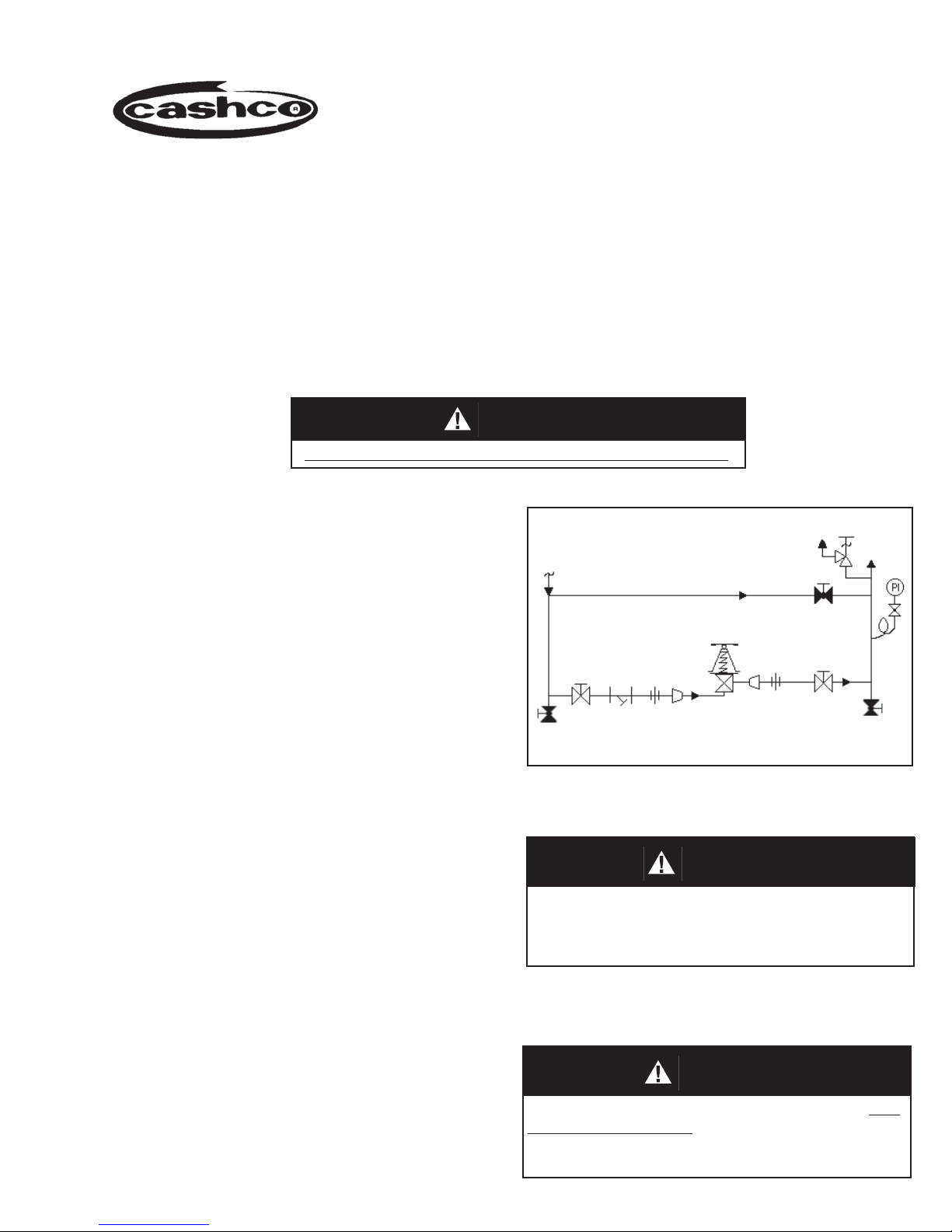
Outlet
@ P2
1. An inlet block valve should always be in stalled.
2. If service application is continuous such that
shutdown is not readily accomplished, it is
recommended that inlet and outlet block valves
and a manual bypass valve be in stalled.
3. An outlet pressure gauge should be lo cat ed
ap prox i mate ly ten pipe diameters down stream
and within sight.
Inlet
@ P1
Blowdown Drain
SRV
Bypass
Model C-CS
Reducing Regulator
Blowdown Drain
4. All installations should include a down stream
re lief device if the inlet pressure could exceed
the pressure rating of any down stream
equip ment.
5. Flow Direction: Install so the flow enters
through the bottom connection and exits the
side connection.
6. Install in a well drained pipe, properly trapped,
with spring chamber (2) in the vertical position
to allow for proper drain ing.
III. PRINCIPLE OF OPERATION
1. Movement occurs as pressure variations
reg is ter on the diaphragm. The registering
pres sure is the outlet, P2 or down stream
pressure. The range spring opposes di a phragm
move ment. As the outlet pressure drops, the
range spring pushes the diaphragm down,
(Recommended Piping Schematic for Pressure Reducing Station)
7. For insulated piping systems, the regulator
should not be insulated.
CAUTION
Installation of adequate overpressure protection
is recommended to protect the regulator from
overpressure and all downstream equipment from
damage in the event of regulator failure.
SECTION III
CAUTION
Do not apply spring load or operate regulator with
hitch pin (21) removed from top of guide post (27 ).
Pre ma ture di a phragm failure will re sult.

opening the port; as outlet pressure in creas es,
the diaphragm pushes up and the port closes.
IV. START-UP
NOTE: The regulator set point must be set
under normal flowing conditions.
1. CCW = Counter Clockwise,
CW = Clockwise.
2. Inspect the unit's nameplate to confirm that
the proper range spring is installed in the
reg u la tor. Apply setpoint pres sures that are
only within the stated range.
2. A complete diaphragm failure will cause the
reg u la tor to fail open.
SECTION IV
7. Slowly open the inlet (upstream) block valve
ob serv ing the outlet (downstream) pressure
gauge. De ter mine if the regulator is flowing
(see NOTE above step 1). If no flow, rotate the
reg u la tor handle (6) CW (viewed from above)
until flow begins. De ter mine if downstream
equip ment is in operation.
8. Continue to slowly open the inlet (upstream)
block valve until fully open.
3. Start with the block valves closed. A bypass
valve may be used to maintain outlet pressure
in the down stream system while performing
the following steps.
4. Relax compression of range spring (7) by
turning handle (6) counter-clockwise (CCW)
until rotation stops. Rotate handle (6) clockwise
(CW) three (3) full revolutions to maintain
spring (7) to di a phragm(17) contact. This
reduces the outlet pres sure setpoint.
5. If piping system includes a bypass valve,
slowly open the bypass valve to preheat the
system piping and to allow slow expansion of
the piping. Ensure proper steam trap op er a tion,
if installed. To prevent overpressurization,
closely mon i tor out let (down stream) pressure
with a gauge. NOTE: If no bypass valve is
installed, extra caution should be used in
starting up a cold system; i.e. do everything
slowly.
6. Crack open the outlet (downstream) block
valve.
9. Continue to slowly open the outlet (down stream)
block valve. When flow is es tab lished steady
enough that the outlet (down stream) block
valve is fully open, begin to slowly close the
bypass valve, if installed, until fully closed.
10. Develop system flow to a level near its
ex pect ed normal rate and reset the regulator
setpoint by turning the handle (6) CW (viewed
from above) to increase outlet pres sure or
CCW to reduce outlet pressure.
11. Reduce system flow to a minimum level and
observe setpoint. Outlet pressure will rise from
the setpoint of Step 10. The max i mum rise
in outlet pressure on de creas ing flow should
not exceed the stated upper limit of the range
spring by greater than 30%; i.e. 10-30 psig
(.69-2.1 Barg) range spring – at low flow the
outlet pres sure should not ex ceed 39 psig (2.7
Barg). If it does, consult factory.
V. SHUTDOWN
1. On systems with a bypass valve, and where
system pressure is to be main tained as the
reg u la tor is shutdown, slow ly open the by pass
valve while closing the inlet block valve. Fully
close the inlet block valve. When on bypass, the
system pres sure must be con stant ly ob served
and man u al ly reg u lat ed.
2 IOM-C-CS
SECTION V
2. If the regulator and system are to both be
shut down, slowly close the inlet block valve.
Close the outlet valve only if reg u la tor re mov al
is required.
CAUTION
DO NOT DEAD-END FLOW DOWN STREAM of
the Mod el C-CS as over pressurizing reg u la tor
may damage internals.

SECTION VI
VI. MAINTENANCE
WARNING
SYSTEM UNDER PRES SURE. Prior to per form ing
any maintenance, isolate the reg u la tor from the
sys tem and relieve all pressure. Failure to do so
could result in personal injury.
A. General:
1. Maintenance procedures here in af ter are
based upon removal of the regulator unit from
the pipeline where installed.
2. Refer to Figures 2 & 3 for basic regulator item
num ber reference ( ) and description.
B. Diaphragm – Trim Replacement:
1. Securely install the regulator in a soft-jawed
vise with the spring chamber (2) di rect ed
upwards. Ensure that the body (1) is not held
in the vise by the Tri-clamp® fitting con nec tions.
The regulator may be held in the vise with
flats on the plug (14). If this method is used,
ensure that the plug (14) is in contact with the
seating area of the body (1) and the face of
the inlet flange of the body (1) is resting on
the vise.
WARNING
SPRING UNDER COMPRESSION. Relieve all
spring (7) compression prior to removing clamp
(13). Failure to do so may result in flying parts that
could result in personal injury.
4. Pull hitch pin (21) and lift up on handle (6) to
remove.
5. Loosen and remove clamp nuts (13B), wash ers
(13D), bolts (13C) and clamps (13A). See
Figure 1.
6. Place matchmarks between body (1) and
spring chamber (2) to assist in final ori en ta tion
when re as sem bled. Lift spring chamber (2)
vertically up and off of body (1) and above
guide post (27) to remove. Note alignment of
spring button (4) tabs (ears) with respect to
slot guides inside spring chamber (2).
7. Remove bearing (26). Lift up and remove
ad just ing screw cap (25.7) and dowel pin (25.8)
as sem bly. NOTE: May need to tap lightly on
O.D. of adjusting screw (25.6) to free Dowel
pin (25.8) from adjusting screw (25.6).
NOTE: The two guide seals (25.9) may/may
not be extracted with as sem bly (25.7,25.8).
Re move guide seals (25.9).
8. Lift up the ad just ing screw (25.6 ) and spring
but ton (4) as an as sem bly to remove. NOTE:
Do not rotate or re move spring button (4) from
ad just ing screw (25.6). Re move spring (7) and
lay aside.
For Metal Seat: Secure the pres sure plate
9.
assembly (27,28 and 29) at the “flats” near
the base of pressure plate (28). Grasp the
lower portion of the plug (14) by the “flats”,
which protrudes from the body (1) inlet,
with soft-jawed pliers or soft-jawed vise and
pro ceed to turn CCW (viewed from above)
for dis as sem bly. NOTE: Main tain firm grasp
of plug (14). After dis en gage ment, plug (14)
could fall out of body (1) and damage seating
surface area. Remove plug (14).
2. Relax range spring (7) by turning handle (6)
CCW (viewed from above) until rotation stops.
Count and record the number of rev o lu tions
in the box below:
Number of revolutions required to relax
range spring: ________
CAUTION
Do not apply spring load or operate regulator with
hitch pin (21) removed from top of guide post (27 ).
Pre ma ture di a phragm failure will re sult.
3. Remove socket head set screw (30) CCW
from end of guide post (27).
IOM-C-CS 3
For Composition Seat: The tail piece (14.3)
may disengage at the plug stem (14.1) joint,
instead of at pressure plate joint(28). If it does,
lift plug stem and pressure plate assembly out
of the body cavity.
Remove seat disc (14.2) from tail piece.
Secure "winged" end of stem (14.1)in a softjawed vise. Use the "flats" on the pressure
plate to rotate CCW to remove pressure plate
assembly.
10. Lay pressure plate assembly (27,28 and 29)
and aside. NOTE: The travel of the guide post
(27) has been factory set. Do not loosen
or adjust the hex nut (29) on pres sure plate
assembly (27,28,29).
 Loading...