

Page 1

INSTALLATION, OPERATION, & MAINTENANCE MANUAL
IOM-C-CS
12-13
MODEL C-CS
“CLEAN STEAM”
PRESSURE REDUCING REGULATOR
SECTION l
I. DESCRIPTION AND SCOPE
Model C-CS is a pressure reducing regulator used to control down stream (outlet or P2) pressure. Inlet and outlet sizes
are 3/4" (DN20), 1" (DN25), 1-1/2" (DN40), 2" (DN50) and 3" (DN80) with Tri-Clamp® fi tting connections. This regula-
tor is primarily designed for steam service at tem per a tures equal to or less than 366°F (185°C); this cor re sponds to
150 psig (10.3 Barg) sat u rat ed steam; however the unit may also be used for clean gaseous or liquid applications.
CAUTION
The Model C-CS should never be used as a shut-off device.
SECTION II
II. INSTALLATION
Outlet
@ P2
1. An inlet block valve should always be in stalled.
2. If service application is continuous such that
shutdown is not readily accomplished, it is
recommended that inlet and outlet block valves
and a manual bypass valve be in stalled.
3. An outlet pressure gauge should be lo cat ed
ap prox i mate ly ten pipe diameters down stream
and within sight.
Inlet
@ P1
Blowdown Drain
SRV
Bypass
Model C-CS
Reducing Regulator
Blowdown Drain
4. All installations should include a down stream
re lief device if the inlet pressure could exceed
the pressure rating of any down stream equip ment.
5. Flow Direction: Install so the fl ow enters
through the bottom connection and exits the
side connection.
6. Install in a well drained pipe, properly trapped,
with spring chamber (2) in the vertical position
to allow for proper drain ing.
III. PRINCIPLE OF OPERATION
1. Movement occurs as pressure variations reg is ter on the diaphragm. The registering pres sure is the outlet, P2 or down stream pressure.
The range spring opposes di a phragm move ment. As the outlet pressure drops, the range
spring pushes the diaphragm down, opening
(Recommended Piping Schematic for Pressure Reducing Station)
7. For insulated piping systems, the regulator
should not be insulated.
CAUTION
Installation of adequate overpressure protection is
recommended to protect the regulator from overpressure and all downstream equipment from damage in
the event of regulator failure.
SECTION III
CAUTION
Do not apply spring load or operate regulator with
hitch pin (21) removed from top of guide post (27 ).
Pre ma ture di a phragm failure will re sult.
Page 2

the port; as outlet pressure in creas es, the
diaphragm pushes up and the port closes.
IV. START-UP
NOTE: The regulator set point must be set
under normal fl owing conditions.
1. CCW = Counter Clockwise,
CW = Clockwise.
2. Inspect the unit's nameplate to confi rm that
the proper range spring is installed in the
reg u la tor. Apply setpoint pres sures that are
only within the stated range.
2. A complete diaphragm failure will cause the
reg u la tor to fail open.
SECTION IV
7. Slowly open the inlet (upstream) block valve
ob serv ing the outlet (downstream) pressure
gauge. De ter mine if the regulator is fl owing
(see NOTE above step 1). If no fl ow, rotate the
reg u la tor handle (6) CW (viewed from above)
until fl ow begins. De ter mine if downstream
equip ment is in operation.
8. Continue to slowly open the inlet (upstream)
block valve until fully open.
3. Start with the block valves closed. A bypass
valve may be used to maintain outlet pressure
in the down stream system while performing
the following steps.
4. Relax compression of range spring (7) by
turning handle (6) counter-clockwise (CCW)
until rotation stops. Rotate handle (6) clockwise (CW) three (3) full revolutions to maintain
spring (7) to di a phragm(17) contact. This
reduces the outlet pres sure setpoint.
5. If piping system includes a bypass valve,
slowly open the bypass valve to preheat the
system piping and to allow slow expansion of
the piping. Ensure proper steam trap op er a tion, if installed. To prevent overpressurization,
closely mon i tor out let (down stream) pressure
with a gauge. NOTE: If no bypass valve is
installed, extra caution should be used in
starting up a cold system; i.e. do everything
slowly.
6. Crack open the outlet (downstream) block
valve.
9. Continue to slowly open the outlet (down stream) block valve. When fl ow is es tab lished
steady enough that the outlet (down stream)
block valve is fully open, begin to slowly
close the bypass valve, if installed, until fully
closed.
10. Develop system fl ow to a level near its ex-
pect ed normal rate and reset the regulator
setpoint by turning the handle (6) CW (viewed
from above) to increase outlet pres sure or
CCW to reduce outlet pressure.
11. Reduce system fl ow to a minimum level and
observe setpoint. Outlet pressure will rise from
the setpoint of Step 10. The max i mum rise
in outlet pressure on de creas ing fl ow should
not exceed the stated upper limit of the range
spring by greater than 30%; i.e. 10-30 psig
(.69-2.1 Barg) range spring – at low fl ow the
outlet pres sure should not ex ceed 39 psig (2.7
Barg). If it does, consult factory.
SECTION V
V. SHUTDOWN
1. On systems with a bypass valve, and where
system pressure is to be main tained as the
reg u la tor is shutdown, slow ly open the by pass
valve while closing the inlet block valve. Fully
close the inlet block valve. When on bypass,
the system pres sure must be con stant ly ob served and man u al ly reg u lat ed.
2 IOM-C-CS
2. If the regulator and system are to both be
shut down, slowly close the inlet block valve.
Close the outlet valve only if reg u la tor re mov al
is required.
CAUTION
DO NOT DEAD-END FLOW DOWN STREAM of the
Mod el C-CS as overpressurizing reg u la tor may
damage internals.
Page 3

SECTION VI
VI. MAINTENANCE
WARNING
SYSTEM UNDER PRES SURE. Prior to per form ing
any maintenance, isolate the reg u la tor from the
sys tem and relieve all pressure. Failure to do so
could result in personal injury.
A. General:
1. Maintenance procedures here in af ter are
based upon removal of the regulator unit from
the pipeline where installed.
2. Refer to Figure 2 for basic regulator item
num ber reference ( ) and description.
B. Diaphragm – Trim Replacement:
1. Securely install the regulator in a soft-jawed
vise with the spring chamber (2) di rect ed upwards. Ensure that the body (1) is not held in
the vise by the Tri-clamp® fi tting con nec tions.
The regulator may be held in the vise with
fl ats on the plug (14). If this method is used,
ensure that the plug (14) is in contact with the
seating area of the body (1) and the face of
the inlet fl ange of the body (1) is resting on
the vise.
WARNING
SPRING UNDER COMPRESSION. Relieve all
spring (7) compression prior to removing clamp
(13). Failure to do so may result in fl ying parts that
could result in personal injury.
2. Relax range spring (7) by turning handle (6)
CCW (viewed from above) until rotation stops.
Count and record the number of rev o lu tions
in the box below:
Number of revolutions required to relax
range spring: ________
4. Pull hitch pin (21) and lift up on handle (6) to
remove.
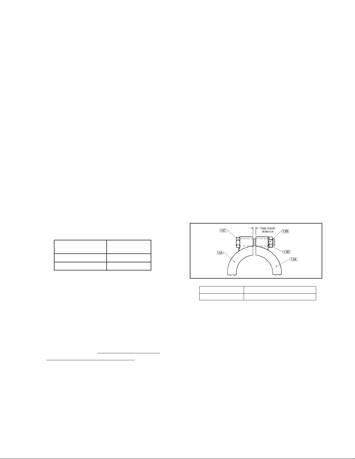
5. Loosen and remove clamp nuts (13B), wash ers (13D), bolts (13C) and clamps (13A). See
Figure 1.
6. Place matchmarks between body (1) and
spring chamber (2) to assist in fi nal ori en ta-
tion when re as sem bled. Lift spring chamber
(2) vertically up and off of body (1) and above
guide post (27) to remove. Note alignment of
spring button (4) tabs (ears) with respect to
slot guides inside spring chamber (2).
7. Remove bearing (26). Lift up and remove ad just ing screw cap (25.7) and dowel pin (25.8)
as sem bly. NOTE: May need to tap lightly on
O.D. of adjusting screw (25.6) to free Dowel
pin (25.8) from adjusting screw (25.6).
NOTE: The two guide seals (25.9) may/may
not be extracted with as sem bly (25.7,25.8).
Re move guide seals (25.9).
8. Lift up to remove the ad just ing screw (25.6 )
and spring but ton (4) as an as sem bly. NOTE:
Do not rotate or re move spring button (4) from
ad just ing screw (25.6). Re move spring (7) and
lay aside.
9. Secure the pres sure plate assembly (27,28
and 29) at the “fl ats” near the base of pressure
plate (28). Grasp the lower portion of the plug
(14) by the “fl ats”, which protrudes from the
body (1) inlet, with soft-jawed pliers or softjawed vice and pro ceed to turn CCW (viewed
from above) for dis as sem bly. NOTE: Main tain
fi rm grasp of plug (14). After dis en gage ment,
plug (14) could fall out of body (1) and damage
seating surface area. Remove plug (14).
10. Remove pressure plate assembly (27,28 and
29) and lay aside. NOTE: The travel of the
guide post (27) has been factory set. Do not
loosen or adjust the hex nut (29) on pres sure
plate assembly (27,28,29).
11a. For Model C-CS :
Remove diaphragm (17), O-ring (16), dia-
phragm gas ket (15) and body (1).
11b. For Model C-CS with Opt.-11:
CAUTION
Do not apply spring load or operate regulator with
hitch pin (21) removed from top of guide post (27 ).
Pre ma ture di a phragm failure will re sult.
3. Remove socket head set screw (30) CCW
from top end of guide post (27).
IOM-C-CS 3
Remove diaphragm (17), diaphragm gaskets
(15), O-ring (18), seal (19), push er plate (20),
O-ring (16) and body (1).
12. Inspect plug (14) and seating surface of body
(1) for excessive wear. Replace all worn
parts.
Page 4
13. Clean gasket (15) and O-ring (16) retaining
surfaces of body (1) and spring chamber (2).
14. Clean all parts in accordance with Own er’s
cleaning procedures. Reposition plug (14)
back into vise with body (1). Ensure that the
plug (14) is in contact with the seating area of
the body (1) and the face of the inlet fl ange of
the body (1) is resting on the vise.
15. Place new diaphragm gasket (15) on body (1)
fl ange.
16. Install O-ring (16). NOTE: For Opt.-11 re po si-
tion push er plate (20) on threaded end of plug
(14) and install O-ring (18) and seal (19). Refer
to Figure 4.
17. Place diaphragm (17) over threaded end of
plug (14). NOTE: The word ‘TOP’ is etched on
one side of the diaphragm and should be visible when looking down on the diaphragm.
18. Place a small amount of medium strength
threadlocker equal to "Blue 242 Loctite" on
threaded end of plug (14). Reassemble pressure plate assembly (27,28 and 29) to plug
(14). Refer to NOTE: in Step 10. Grasp the
parts and rotate pres sure plate assembly
(27,28,29) CW until wrench tight (met al-tometal con tact); Torque values not to ex ceed
the following:
together by hand. NOTE: Top of dowel
pin (25.8) should be fl ush with top surface
of adjusting screw cap (25.7).
22. Install new bearing (26) on top of upper
guide assembly (25).
23. Align slot guides inside spring chamber
(2) with spring button (4) tabs (ears) and
position on to body (1). Align with match
marks of step 6. previous.
24. Place handle (6) over end of guide post
(27) coming to rest on adjusting screw cap
(25.7). Insert hitch pin (21) into hole through
end of guide post (27). Apply Loctite 242
or equalivent to threads of set screw (30)
install into top of guide post (27) and tighten
securely.
25. Reposition clamps (13A) around body (1)
and spring chamber (2) fl anges. Insert clamp
bolts (13C), washers (13D) and tighten
clamp nuts (13B) in alternating pattern.
NOTE: Gap be tween clamp (13A) halves
should be equal in size. Gap and torque
re quire ments are as follows:
Body Size
in (DN)
3/4"-1 1/2" (20-40)
2" - 3" (50-80)
Torque
in-lbs (N-m)
100 (11)
270 (31)
19. Center/align the above pressure plate/
diaphragm assembly on the di a phragm (17)
fl ange sur face in the body (1).
20. Position spring (7) on to hub of pressure plate
(28). Place adjusting screw (25.6) - with spring
button (4) - over end of guide post (27) and
into spring (7) cav i ty. NOTE: Apply a small
amount of Emhart Bostik White Food Grade
“Never-Seez” or equiv a lent to threads of ad just ing screw (25.6) Do Not rotate adjusting
screw (25.6) or spring button (4).
21. Install new guide seals (25.9) in adjusting
screw cap (25.7). NOTE: There are two sizes
of u-cup seals - install the seal with the bigger diameter spring fi rst, open face into the
cap recess. Install the second u-cap seal,
open face exposed to face of adjusting screw
(25.6). Slide adjusting screw cap (25.7) over
end of guide post (27). Align dowel pin (25.8)
with hole in adjusting screw (25.6) and press
Figure 1: Clamp Arrangement.
Gap Torque
Equal Distance 225-250 in-lbs (25-28 N-m)
26. Reapply compression to the range spring
(7) by rotating handle (6) CW as per the
num ber of revolutions re cord ed in VI.B.2.
27. Return to Section II for Installation and
Sec tion IV for Start-up.
4 IOM-C-CS
Page 5

SECTION VII
VII. ORDERING INFORMATION
NEW REPLACEMENT UNIT vs PARTS "KIT" FOR FIELD REPAIR
To obtain a quotation or place an order, please retrieve the Serial Number and Product Code that was
stamped on the metal name plate and attached to the unit. This information can also be found on the
Bill of Material ("BOM"), a parts list that was provided when unit was originally shipped. (Serial Number
typically 6 digits). Product Code typical format as follows: (last digit is alpha character that refl ects revi-
sion level for the product).
–
NEW REPLACEMENT UNIT:
Contact your local Cashco, Inc., Sales Rep re sen ta tive with the Serial Number and Product code.
With this information they can provide a quotation
for a new unit including a complete description,
price and availability.
CAUTION
Do not attempt to alter the original construction
of any unit without assistance and approval from
the factory. All purposed changes will require a
new name plate with appropriate ratings and new
product code to accommodate the recommended
part(s) changes.
PARTS "KIT" for FIELD REPAIR:
Contact your local Cashco, Inc., Sales Rep re sen ta tive with the Serial Number and Product code.
Identify the parts and the quantity required to repair
the unit from the "BOM" sheet that was provided
when unit was originally shipped.
–
7
NOTE: Those part numbers that have a quantity indicated
under "Spare Parts" in column "A” refl ect minimum
parts required for inspection and rebuild, - "Soft
Goods Kit". Those in column “B” include minimum
trim replacement parts needed plus those "Soft
Goods" parts from column "A".
If the "BOM" is not available, refer to the crosssectional drawings included in this manual for part
identifi cation and selection.
A Local Sales Representative will provide quotation
for appropriate Kit Number, Price and Availability.
The contents of this publication are presented for informational purposes only, and while every effort has been made to ensure their accuracy, they are not to be
construed as warranties or guarantees, express or implied, regarding the products or services described herein or their use or applicability. We reserve the right to
modify or improve the designs or specifi cations of such product at any time without notice.
Cashco, Inc. does not assume responsibility for the selection, use or maintenance of any product. Responsibility for proper selection, use and maintenance of any
Cashco, Inc. product remains solely with the purchaser.
IOM-C-CS 5
Page 6
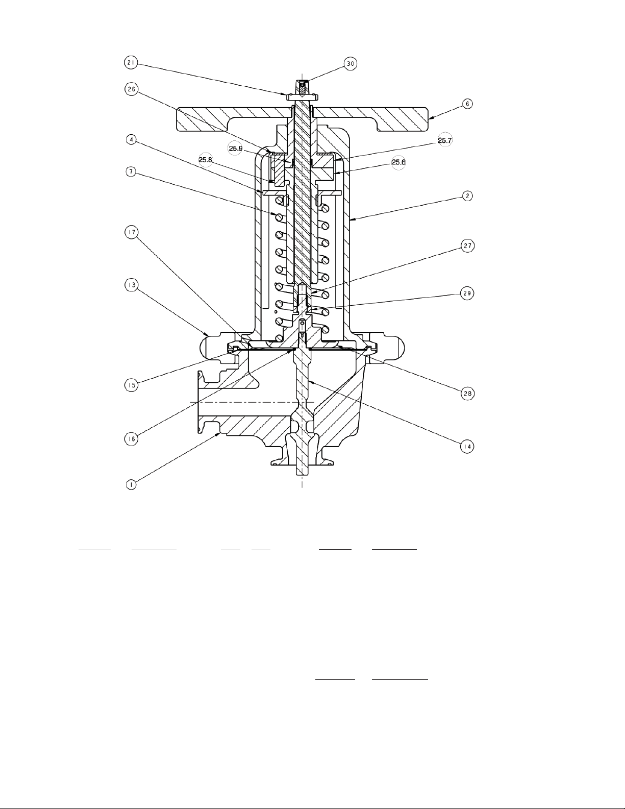
Figure 2
Forged body.
Repair Parts
Item No. Description Kit A Kit B
1 Body
2 Spring Chamber
4 Spring Button
6 Handle
7 Range Spring
13 Clamp (2 Req'd)
14 Plug
15 Gasket (Diaphragm)
16 O-ring (Plug)
17 Diaphragm
18 O-ring
19 Seal
20 Pusher Plate
21 Hitch Pin
25 Upper Guide Assembly
25.6 Adjusting Screw
25.7 Adjusting Screw Cap
25.8 Dowel Pin
25.9 Guide Seals (2 Req'd) * **
1
**
* **
* **
* **
* **
* **
Item No. Description
26 Bearing
27 Guide Post
28 Pressure Plate
29 Nut Hex Jam
30 Set Screw
1
Refer to Figure 1 for Clamp and related item
numbers.
Not Shown:
Item No. Description
11 Name Plate
12 Drive Screw
6 IOM-C-CS
Page 7
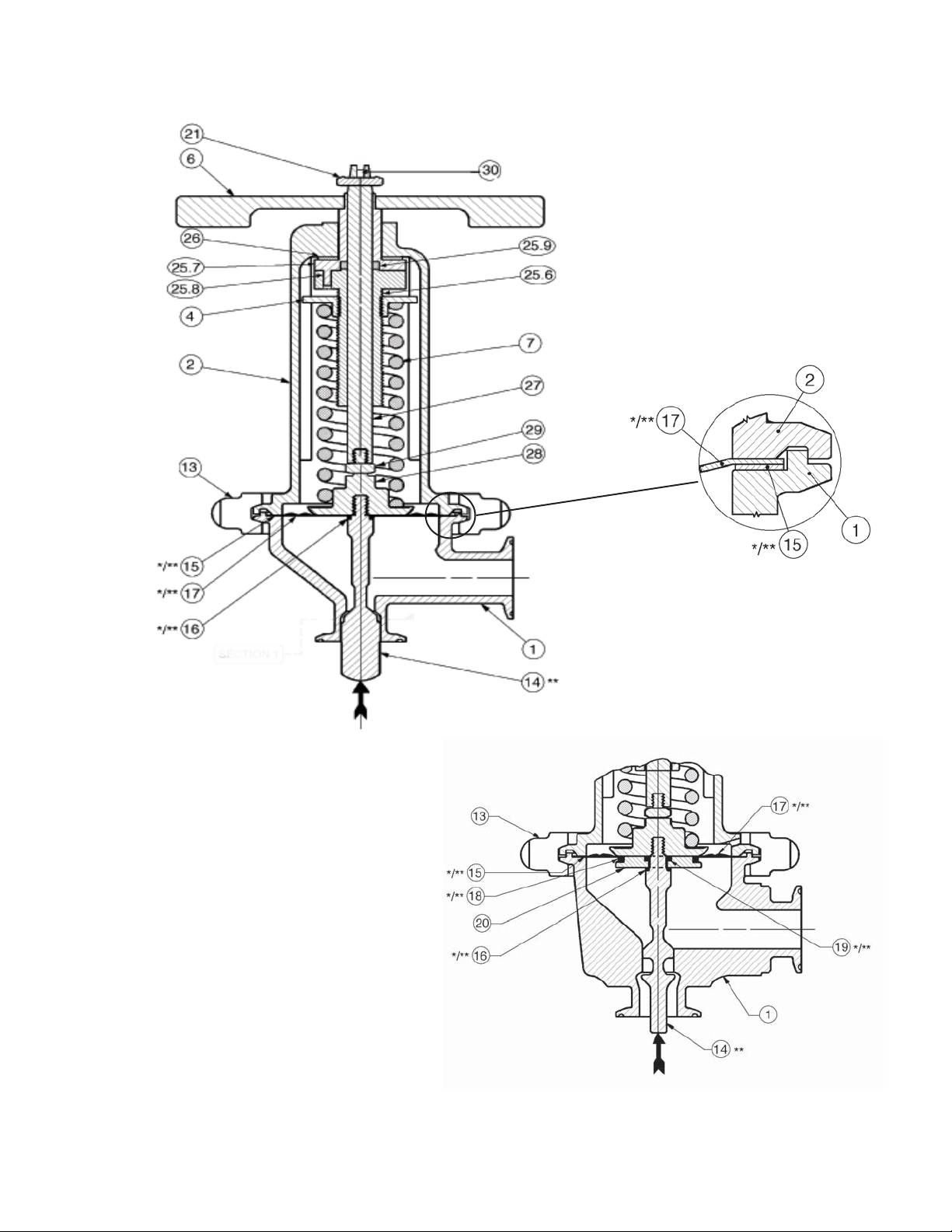
See the previous page for Item Number Descriptions.
Figure 3
Investment Cast body.
Figure 4: Option-11, Diaphragm Restraint
(Forged Body Shown)
IOM-C-CS 7
Page 8

Cashco, Inc.
P.O. Box 6
Ellsworth, KS 67439-0006
PH (785) 472-4461
Fax. # (785) 472-3539
www.cashco.com
email: sales@cashco.com
Printed in U.S.A. IOM-C-CS
Cashco GmbH
Handwerkerstrasse 15
15366 Hoppegarten, Germany
PH +49 3342 4243135
Fax. No. +49 3342 4243136
www.cashco.com
Email: germany@cashco.com
Cashco do Brasil, Ltda.
Al.Venus, 340
Indaiatuba - Sao Paulo, Brazil
PH +55 11 99677 7177
Fax. No.
www.cashco.com
Email: brazil@cashco.com
 Loading...