

Page 1
INSTALLATION, OPERATION & MAINTENANCE MANUAL (IOM)
MODELS C27 - C53
SPRING/DIAPHRAGM LINEAR PNEUMATIC ACTUATORS
SECTION I
I. DESCRIPTION AND SCOPE
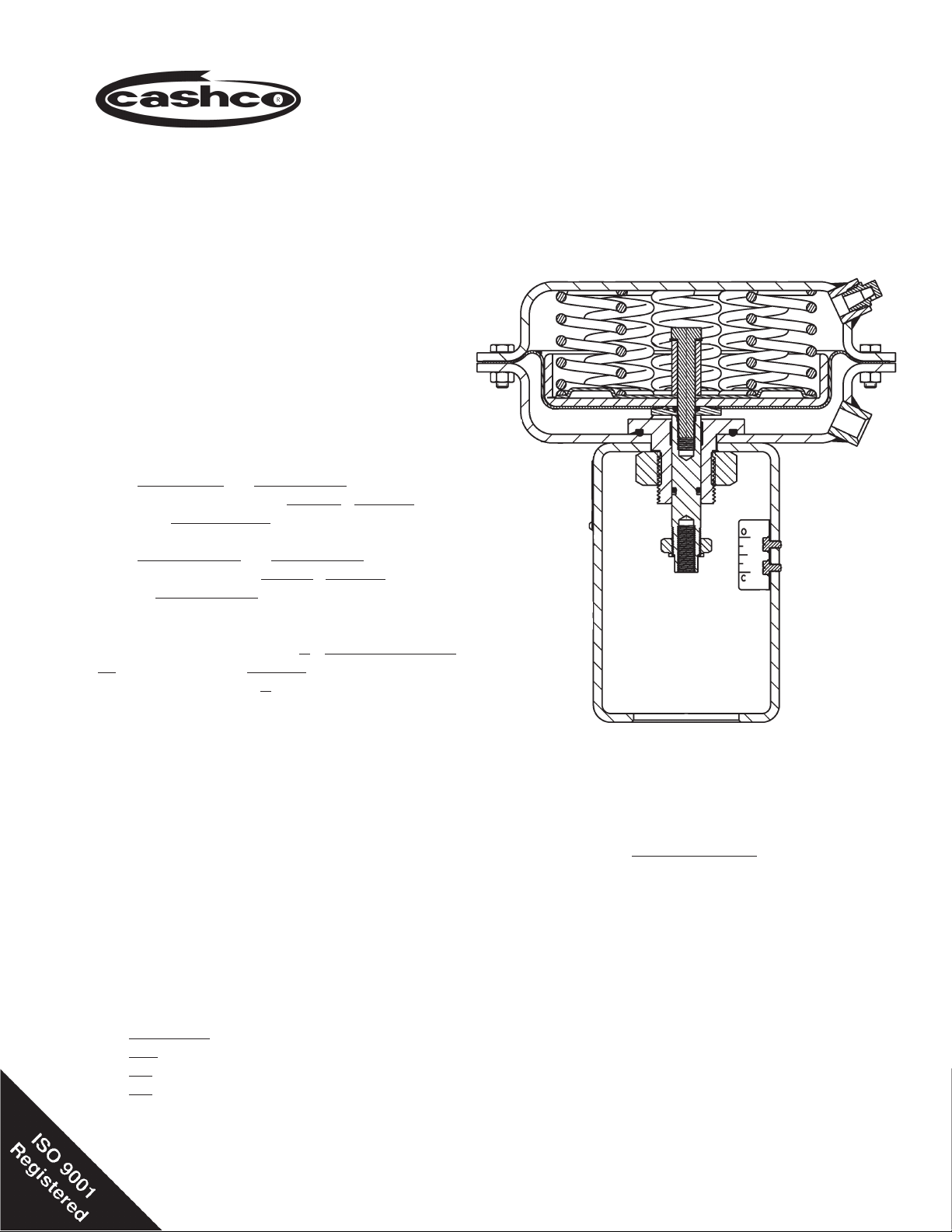
Actuator models C27 and C53 are multi-spring,
single acting, spring opposed, linear actuators used
with Cashco sliding stem (linear), globe-style control
valves. The “R” denotes“ reverse”acting arrangement;
the “D” denotes “direct” acting arrangement and are
reversible in the fi eld.
“D” = Direct action; on increasing air loading
pressure,the actuator stem extends. Fail-safe position
is with the stem retracted.
IOM-C27-C53
12-13
“R” = Reverse action; on increasing air loading pressure, the actuator stem retracts. Fail-safe position is
with the stem extended.
When coupled with a globe-style control valve with
pushdown to close action, a “D”- direct acting actuator will provide valve “fail open” action;“D” = ATC-FO.
When coupled with an “R” - reverse acting actuator,
will provide valve “fail closed” action; “R” = ATO-FC.
SECTION II
II. REFERENCES
Refer to the Control Valve Technical Bulletin this
actuator is unitized with for complete tech ni cal
specifi cations.
Refer to following Installation, Operation & Main te nance Manuals (IOM’s) for other devices that maybe
mounted to C27-C53 actuators:
Positioners:
P/P: www.cashco.com/techbulletins/9540l.pdf
I/P: www.cashco.com/techbulletins/srd991.pdf
I/P: www.cashco.com/iom/PS2iom.pdf
Shown w/ATO-FC Action
ABBREVIATIONS
ATO-FC ... Air-to-Open, Fail Close
ATC-FO ... Air-to-Close, Fail Open
CCW ........ Counter Clockwise
CW ........... Clockwise
D or DIR ... Direct Acting
R or REV.. Reverse Acting
IAS ........... Instrument Air Supply
IOM .......... Installation, Operation and Maintenance
Man u al
SIG .......... Output Signal from Instrument
LOAD ....... Positioner Output Air Pressure
V .............. Vent
Page 2

2
IOM-C27-C53
III. INSTALLATION
A. Orientation:
SECTION III
B. Air Supply:
1. Recommended actuator major axis orientation
with any model of Cashco control valve body,
is upwards in a horizontal pipe.
2. Actuator axis may be horizontal when valve
is in a vertical pipe.
3. Outdoors, all installations must be oriented
any angle from horizontal-to-vertical.
4. Models C27 and C53 actuators are not recommended for installation oriented downwards
in either “D” or “R” action.
5. In no case is additional weight to be applied
to the actuator when installed in an orientation
other than vertical; i.e. the valve is unsafe as
a “step” to support personnel.
IV. MAINTENANCE
A. General:
1. Hereafter, all maintenance, disassembly,
etc., is assumed to be done in an indoor
shop.
2. An actuator assembly (AA) is unitized with a
body assembly (BA). Reference should be
made to the body IOM for instructions about
the specifi ed body assembly (BA) utilized
with the actuator.
3. Where the body is not being removed from
the actuator, special care MUST be exhibited to prevent valve stem rotation during
any disassembly or reassemble for all valve
models. Following this procedure will ensure
not damaging seating surfaces.
4. Remove instrument tubing, airset, positioner,
and any other accessory that maybe mounted on the control valve unit (AA, BA).
5. All indicated Item Numbers that are with respect to body (BA) IOM will be in parenthesis
and underscored; i.e. (20); the same is true
for positioner parts. All Item Numbers that
are with respect to this manual are not underscored; i.e. (19).
1. Recommendation is that a desiccant dried,
instrument quality air supply be used.
Such a supply is recommended for outdoors installations, and is required in areas of freezing weather conditions.
2. If air supply contains moisture and/or lubricating oil, the air should be fi ltered with
a coalescing type of fi lter prior to use in
stroking the actuator.
3. Failure to remove moisture will cause corrosion to internals of casings (1,2).
4. Connections for the air supply are 1/4” female NPT. A suitable pipe thread sealant
is recommended to be used when installing the pipe or tube fi tting. Exhibit care to
prevent the sealant from getting inside the
tube/pipe.
SECTION IV
B. Diaphragm Removal/Replacement:
NOTE: Actuator (AA) must be separated from
the body (BA) in order to replace O-rings
(15, 16 &17) and diaphragm (7). Refer to
specifi ed body (BA) IOM for instructions to
remove actuator (AA).
NOTE: If actuator (AA) has Handwheel refer to
Step E and remove.
1. Secure the yoke (3) in a vise. Orient with
the (AA) upwards.
2. All air pressure must be released from the
actuator casings (1,2).
3. Take note of alignment of supply ports on
top and bottom cases (1,2); used to assist
with ori en ta tion when actuator is re- as sem bled.
WARNING
SPRINGS UNDER COMPRESSION! To relax spring com-
pression remove case bolting equally in an alternating
pattern. Ensure that all "short" bolting is removed
fi rst.
IOM-C27-C53
2
Page 3

IOM-C27-C53
3
4. Loosen all fl ange bolting (18,19,20,21) two
revolutions. Pry apart the casings (1,2) if
“stuck” together.
5. In one revolution increments loosen all op pos ing nuts (20, 21) until the short bolting
(18, 20) disengages and can be removed.
Con tin ue loosening long nuts (21) in the
alternating, one revolution pattern ensuring that the cas ings (1,2) are being “pushed
apart”, until the long bolting (19, 21) is disengaged and removed.
For Air-to-Close Construction:
6. Remove top case (1). Secure the fl ats on
the lower end of the actuator stem (6) with
a wrench. With a second wrench rotate
the upstop fl ex nut (52) CCW and remove.
Note: Item (52) not used if actuator has
handwheel.
7. Re-secure the fl ats on stem and with a 9/16”
socket wrench rotate bolt (12) CCW to remove.
For Air-to-Open Construction:
15. Remove top case (1). Place matchmarks
on spring plate (9) to mark location of the
springs (10). Remove springs (10).
16. Rotate upstop fl ex nut (52) CCW and remove.
Note: Item (52) not used if actuator has
handwheel assembly.
17. Secure the fl ats on stem (6) and with a 9/16”
socket wrench rotate bolt (12) CCW to remove.
18. Remove lock washer (22) and spacer (5).
19. Remove spring plate (9) diaphragm plate (8),
diaphragm (7), o-ring (15) and diaphragm
washer (14).
20. Grasp stem (6) with hand and pull down thru
the attachment hub (4). Remove o-ring (17)
from stem (6). Lubricate new o-ring (17) with
Lubri-plate or equivalent and install on stem
(6).
8. Lift out lock washer (22), diaphragm washer
(14) and O-ring (15). Remove diaphragm (7).
NOTE: To replace stem bushing (39) and o-ring
(17) refer to Step F.
9. Install new diaphragm (7) over the diaphragm
plate (8), convoluted side down. Align bolt
holes in diaphragm with holes in lower case.
10. Install new new o-ring (15) and reposition
washers (14 & 22) on top of diaphragm.
11. Apply Loc-tite #242 or equal to stem bolt (12)
threads, tighten stem bolt (12) to actuator
stem (6) with 35 ft-lbs. torque.
12. Place upper case on lower case align top and
bottom cases (1,2) per B.3 previous. Install
long bolting (19) and nuts (21) equally spaced
around the bolt circle - fi nger tighten.
13. Install remaining short bolts (18) and nuts
(20). Torque all bolting to 75 in-lbs.
14. Thread upstop fl ex nut (52) [coupling as-
sembly (33) for handwheel option] onto the
actuator stem (6) and engage until just past
stem fl ats. NOTE: Upstop position cannot
be set until actuator is mounted on the body
and the bench range is set.
21. From the top of the attachment hub (4) extract
the stem bushing (39). Install new bushing.
22. Grasp stem (6) with hand and from below
the lower case (2) push the stem up thru the
attachment hub (4) until the bottom end of
the stem aligns with the “C” close mark on
the indicator plate (23).
23. Reposition diaphragm washer (14) “o-ring
side up” and new o-ring (15) on top of attachment hub (4).
24. Place the diaphragm plate (8) inside the
diaphragm (7) and carefully place both on
the diaphragm washer (14). Align bolt holes
in diaphragm with holes in lower case.
25. Align the spring plate (9) and stem spacer (5)
over the center hole of the diaphragm plate
(8).
26. Apply Loc-tite #242 to stem bolt (12) threads
and insert down through stacked parts and
rotate CW to engage threaded end of stem
(6). Tighten stem bolt (12) to actuator stem
(6) with 35 ft-lbs. torque.
27. Place springs (10) equally spaced around
the spring plate (9). See Step 15 previous
for matchmarks.
IOM-C27-C53
3
Page 4

4
IOM-C27-C53
28. Refer to B.3 previous, align top and bottom
cases (1,2). Install long bolting (19) and nuts
(21) equally spaced around the bolt circle fi nger tight.
9. Place the diaphragm plate (8) inside the
diaphragm (7) and carefully center both on
the diaphragm washer (14). Align bolt holes
in diaphragm with holes in lower case.
29. Install remaining short bolts (18) and nuts
(20). Torque all bolting to 75 in-lbs.
30. Thread upstop fl ex nut (52) [coupling assem-
bly (33) for handwheel option] CW onto the
actuator stem (6) and engage until just past
stem fl ats. NOTE: Upstop position cannot
be set until actuator is mounted on the body
and the bench range is set.
C. Changing Action from Direct to Reverse; i.e.
From ATC to ATO.
NOTE: Not necessary to remove actuator assembly from body assembly, unless supplied
with Handwheel Assembly.
1. Follow steps from B.1 thru B.5 then continue
as follows.
NOTE: DO NOT rotate actuator stem (6) or body
stem.
2. Secure both stem jam nuts with wrenches
and rotate the lower nut fi rst down to thread
base of the stem, followed by the upper nut.
10. Align center holes in the spring plate (9) and
stem spacer (5) with the center hole of the
diaphragm plate (8).
11. Apply Loc-tite #242 to stem bolt (12) threads
and insert down through stacked parts.
Rotate CW to engage threaded end of stem
(6). Secure the fl ats on the lower end of the
actuator stem (6) with a wrench. Tighten
stem bolt (12) to actuator stem (6) with 35
ft-lbs. torque.
NOTE: DO NOT rotate actuator stem (6) or body
stem while plug is touching the seat surface.
12. Place springs (10) equally spaced around
the spring plate (9).
13. Refer to B.3 previous, align top and bottom
cases (1,2). Install long bolting (19) and
nuts (21) equally spaced around the bolt
circle - fi nger tight.
14. Install remaining short bolts (18) and nuts
(20). Torque all bolting to 75 in-lbs.
3. Secure the fl ats on the lower end of the actua-
tor stem (6) with a wrench. With a second
wrench rotate the upstop fl ex nut (52) CCW 5
revolutions. (Required to help release spring
preload when stem bolt (12) is removed.)
4. Remove top case (1). Re-secure the fl ats on
stem and with a 9/16” socket wrench rotate
bolt (12) CCW and remove.
5. Lift out lock washer (22), diaphragm washer
(14) and O-ring (15). Remove diaphragm (7).
6. Remove diaphragm plate (8), spring plate
(9), stem spacer (5) and springs (10).
7. With hand pressure - push stem (6) down to
where bottom of stem (6) aligns with the “C”
close mark on the indicator plate (23.
NOTE: DO NOT rotate actuator stem (6) or body
stem while plug is touching the seat surface.
8. Re-assemble by placing diaphragm washer
(14) “o-ring side up” and new o-ring (15) on
attachment hub (4).
Rotate upstop fl ex nut (52) CW up the
15.
actuator stem (6) until just past stem fl ats.
NOTE: Upstop position cannot be set until
the bench range is set.
16. Lift indicating washer up to bottom of stem
(6) and thread both jam nuts up secure
underneath the indicating washer.
D. Changing Action from Reverse to Direct; i.e.
From ATO to ATC.
NOTE: Not necessary to remove actuator assembly from body assembly, unless supplied
with Handwheel Assembly.
1. Follow steps from B.1 thru B.5, then continue
as follows.
2. Remove top case (1) and springs (10).
3. Secure the fl ats on stem (6) and with a
9/16” socket wrench rotate bolt (12) CCW
to remove.
NOTE: DO NOT rotate actuator stem(6) or body
stem while plug is touching the seat surface.
IOM-C27-C53
4
Page 5

IOM-C27-C53
5
4. Remove lock washer (22) and stem spacer
(5).
5. Remove spring plate (9) diaphragm plate (8),
diaphragm (7), o-ring (15) and diaphragm
washer (14).
E. To Remove Handwheel Assembly.
For Air to Close Construction:
1. Rotate locknut (36) CCW two revolutions.
Rotate handwheel (31.2) CCW until it spins
freely.
6. Grasp stem (6) with hand and push upwards
to where indicating washer aligns with the
“O” open mark on the indicator plate (23).
7. Place springs (10) equally spaced in bottom
case (2) around the attachment hub (4).
8. Place stem spacer (5) on top of stem (6).
Carefully position spring plate (9) over top
the tops of the springs and spacer. Ensure
the springs, spacer and spring plate are
properly engaged.
9. Carefully set the diaphragm plate (8) on top
of the spring plate (9).
10. Install diaphragm (7) over the diaphragm
plate (8) and align with bolt holes in case
(2). Insert new o-ring (15) into groove in the
diaphragm washer (14).
11. Position diaphragm washer (14) “o-ring
side down” and lock washer (22) on top of
diaphragm (7).
12. Apply Loc-tite #242 to stem bolt (12) threads
and insert down through stacked parts,
rotate CW to engage threaded end of stem
(6). Secure the fl ats on the lower end of the
actuator stem (6) with a wrench. Tighten
stem bolt (12) to actuator stem (6) with 35
ft-lbs. torque.
2. With hammer and pointed punch, tap the
spring pin (35) out of the handwheel and
remove handwheel.
3. Remove nuts (38) and lock washer (48) from
cap screws (37). DO NOT let bracket as-
sembly fall as cap screws are removed. Lift
bracket assembly up such that the opening
of the pivot brackets (26) slip over the posts
on the coupling assembly (33). Set bracket
assembly aside.
4. Provide a temporary air supply with an in-line
ad just able airset regulator to the actuator
con nec tion.
5. Pressurize the ac tu a tor to a pres sure level
2-3 psig (0.1-0.2 Barg) above the lower
pres sure lev el of the bench setting; i.e. for a
5-15 psig (.34 -1.0 Barg) range, set pressure
at 7-8 psig (0.48-0.55 Barg).
6. Rotate the coupling assembly (33) CCW to
remove and release all air pres sure from
ac tu a tor.
Return to Section IV. B. Step 1.
For Air to Open Construction:
1. Rotate locknut (36) CCW up to base of
handwheel. Rotate handwheel (31.2) CW
until it spins freely.
NOTE: DO NOT rotate actuator stem (6) or body
stem while plug is touching the seat surface.
13. Refer to B.3 previous, align top and bottom
cases (1,2). Install long bolting (19) and
nuts (21) equally spaced around the bolt
circle - fi nger tight.
14. Install remaining short bolts (18) and nuts
(20). Torque all bolting to 75 in-lbs.
Rotate upstop fl ex nut (52) to align just past
15.
the fl ats on the stem (6). NOTE: Upstop
position cannot be set until the bench range
is set.
IOM-C27-C53
2. With hammer and pointed punch, tap the
spring pin (35) out of the handwheel and
remove handwheel.
3. Remove nuts (38) and lock washer (48) from
cap screws (37). DO NOT let bracket assembly fall as cap screws are removed. Lift
bracket assembly up such that the opening
of the pivot brackets (26) slip over the posts
on the coupling assembly (33). Set bracket
assembly aside.
4. Rotate coupling assembly (33) CCW to
remove.
Return to Section IV. B. Step 1.
5
Page 6

6
IOM-C27-C53
F. Bushing & O-ring Replacement ATC only.
(Extension of IV. B. Steps 1 - 8.)
1. Remove diaphragm plate (8), spring plate
(9) and stem spacer (5).
2. Place matchmarks on lower case (2) to
mark location of the springs (10). Remove
springs (10).
6. Reset springs (10) equally spaced around
the lower case (2). See Step 2 previous for
matchmarks.
7. Place stem spacer (5) on top of stem (6).
Carefully position the spring plate (9) over
the tops of the springs and spacer. Make
sure the springs, spacer and spring plate are
properly engaged.
3. Grasp stem (6) with hand and pull down thru
attachment hub (4). Remove o-ring (17)
from stem (6). Lubricate new o-ring (17)
with Lubri-plate or equivalent and install on
stem (6).
4. From the top of the attachment hub (4)
extract the stem bushing (39). Install new
bushing.
5. Grasp stem (6) with hand and from below
the lower case (2) push the stem back up
thru the attachment hub (4) until the bottom
end of the stem aligns with the “O” open
mark on the indicator plate (23).
8. Carefully set the diaphragm plate (8) on top
of the spring plate (9).
9. Return to Section IV. B. Step 9.
IOM-C27-C53
6
Page 7

IOM-C27-C53
7
SECTION V
V. TROUBLE SHOOTING GUIDE
NOTE: Cashco, Inc. recommends that if the casings are unbolted, the diaphragm, o-ring and TFE tape guide bushing
should always be replaced.
1. Air Leakage; Reverse action units. Diaphragm removal/replacement per Section IV. MAINTENANCE in its entirety.
Symptom Cause-Remedy
A. Leakage at diaphragm-to-lower casing fl ange or thru vent
plug.
B. Leakage from around stem and attachment hub. B. Replace O-ring (17).
2. Air Leakage; Direct action units. Diaphragm removal/replacement per Section IV. MAINTENANCE in its entirety.
Symptom Cause-Remedy
Leakage at diaphragm-to-upper casing joint or thru vent
A.
plug.
A1.
Overpressure. Check source of air supply and determine
if pressure is greater than indicated in Technical Bulletin;
reset airset pressure as required.
A2.
Tighten fl ange bolting.
A3.
Faulty seal at stem-diaphragm-seal joint. Remove upper
case - diaphragm. Install new o-ring (15).
Overpressure. Check source of air supply and determine
A1.
if pressure is greater than indicated in Technical Bulletin;
reset airset pressure as required.
Tighten fl ange bolting.
A2.
Faulty seal at stem-diaphragm-seal joint. Remove upper
A3.
case - diaphragm washer. Install new o-ring (15).
3. Unstable stroking.
Symptom Cause-Remedy
A. Intermittent screaching noise, jumpy motion; positioner/
controller loading stable
B. Positioner output unstable; positioner input signal stable. B1.
C. Controller output signal unstable. C1.
A1.
Excessive valve packing friction. Maintain valve packing
per valve instructions.
A2.
Misalignment of valve stem-to-actuator stem; realign per
valve instructions.
A3.
Excessive valve guide wear. Maintain valve per valve
instructions.
A4.
Flow induced instability thru valve. Stabilize
A5.
Install high range spring in actuator; i.e. increase bench
setting level.
Refer to the positioner IOM
B2.
Reduce positioner gain.
B3.
Re-calibrate positioner.
Stabilize controller by increasing proportional band,
adding reset, adding rate, or combinations of all.
C2.
Unstable process. Snub process if able. Stabilize process.
IOM-C27-C53
7
Page 8

8
IOM-C27-C53
4. Actuator can not deliver full stroke.
Symptom Cause-Remedy
A. Valve can not fully close for “Direct Action-ATC-FO”
arrangement; or valve can not fully open for “Reverse
Action-ATO-FC” arrangement.
B. Valve can not fully open for “Direct Action-ATC-FO”
arrangement; or valve can not fully close for “Reverse
Action-ATO-FC” arrangement.
A1.
Insuffi cient air supply pressure. Check Technical Bulletin
for proper air supply pressure.
A2.
Manual handwheel out of “neutral” position.
A3.
If equipped with a pneumatic positioner, positioner maybe
in “bypass” mode.
A4.
Excessive pressure drop. Check technical bulletin of
control valve for maximum allowable ∆P.
A5.
Bench range not properly calibrated. Check calibration or
stem overall length and re-calibrate per valve instructions.
Restriction in air supply line limiting volume available
A6.
Restriction in valve. Gain access to the valve’s internals
A7.
for any debris.
B1.
Insuffi cient air supply pressure. Check Technical Bulletin
for proper air supply pressure.
B2.
Manual handwheel out of “neutral” position.
B3.
If equipped with a pneumatic positioner, positioner maybe
in “bypass” mode.
B4.
Excessive pressure drop. Check technical bulletin of
control valve for maximum allowable ∆P.
B5.
Bench range not properly calibrated. Check calibration or
stem overall length and re-calibrate per valve instructions.
Restriction in air supply line limiting volume available
B6.
Restriction in valve. Gain access to the valve’s internals
B7.
for any debris.
IOM-C27-C53
8
Page 9

IOM-C27-C53
9
SECTION VI
VI. ORDERING INFORMATION
NEW REPLACEMENT UNIT vs PARTS "KIT" FOR FIELD REPAIR
To obtain a quotation or place an order, please retrieve the Serial Number and Product Code that was stamped on
the metal name plate and attached to the unit. This information can also be found on the Bill of Material (“BOM”),
a parts list that was provided when unit was originally shipped. (Serial Number typically 6 digits). Product Code
typical format as follows: (last digit is alpha character that refl ects revision level for the product).
–
NEW REPLACEMENT UNIT:
Contact your local Cashco, Inc., Sales Rep re sen ta tive with the Serial Number and Product code.
With this information they can provide a quotation
for a new unit including a complete description,
price and availability.
CAUTION
Do not attempt to alter the original construction of any
unit without assistance and approval from the factory. All
purposed changes will require a new name plate with appropriate ratings and new product code to accommodate
the recommended part(s) changes.
–
7
PARTS "KIT" for FIELD REPAIR:
Contact your local Cashco, Inc., Sales Rep re sen ta tive with the Serial Number and Product code.
Identify the parts and the quantity required to repair
the unit from the “BOM” sheet that was provided
when unit was originally shipped.
NOTE: Those part numbers that have a quantity indicated
under "Spare Parts" in column "A” refl ect minimum
parts required for inspection and rebuild, - "Soft
Goods Kit". Those in column “B” include minimum
trim replacement parts needed plus those "Soft
Goods" parts from column "A".
If the "BOM" is not available, refer to the crosssectional drawings included in this manual for part
identifi cation and selection.
A Local Sales Representative will provide quotation
for appropriate Kit Number, Price and Availability.
The contents of this publication are presented for informational purposes only, and while every effort has been made to ensure their accuracy, they are not to be
construed as warranties or guarantees, express or implied, regarding the products or services described herein or their use or applicability. We reserve the right to
modify or improve the designs or specifi cations of such product at any time without notice.
Cashco, Inc. does not assume responsibility for the selection, use or maintenance of any product. Responsibility for proper selection, use and maintenance of any
Cashco, Inc. product remains solely with the purchaser.
IOM-C27-C53
9
Page 10

10
IOM-C27-C53
C27 Actuator
ATC - FO Action
10
Item No. De scrip tion
1 Case - Top
2 Case - Bottom
3 Yoke
4 Attachment Hub
5 Stem Spacer
6 Stem
7 Diaphragm ‡
8 Diaphragm Plate
9 Spring Plate
10 Spring
11 Hub Nut
12 Stem Bolt
14 Diaphragm Washer
15 Diaphragm Washer O-ring ‡
16 Attachment Hub O-ring ‡
17 Stem O-ring ‡
Item No. De scrip tion
18 Case Bolts - Short
20 Case Nut - Short
22 Stem Lock Washer
23 Indicator Plate
24 Indicator Plate Screw
39 Stem Tefl on Bushing ‡
40 Name Plate
41 Drive Screw
47 Vent Plug
52 Stem Stop Nut
Not Shown
19 Case Bolts - Long
21 Case Nuts - Long
49 Warning Plate
(Item number for Indicating Washer
is unique to Model)
‡ Recommended replacement parts.
IOM-C27-C53
Page 11

IOM-C27-C53
11
C27 Actuator
ATO - FC Action
Item No. De scrip tion
1 Case - Top
2 Case - Bottom
3 Yoke
4 Attachment Hub
5 Stem Spacer
6 Stem
7 Diaphragm ‡
8 Diaphragm Plate
9 Spring Plate
10 Spring
11 Hub Nut
12 Stem Bolt
14 Diaphragm Washer
15 Diaphragm Washer O-ring ‡
16 Attachment Hub O-ring ‡
17 Stem )-ring ‡
IOM-C27-C53
Item No. De scrip tion
18 Case Bolts - Short
20 Case Nut - Short
22 Stem Lock Washer
23 Indicator Plate
24 Indicator Plate Screw
39 Stem Tefl on Bushing ‡
40 Name Plate
41 Drive Screw
47 Vent Plug
52 Stem Stop Nut
Not Shown
19 Case Bolts - Long
21 Case Nuts - Long
49 Warning Plate
‡ Recommended replacement parts.
11
Page 12

12
IOM-C27-C53
C53 Actuator
ATC - FO Action
12
Item No. De scrip tion
1 Case - Top
2 Case - Bottom
3 Yoke
4 Attachment Hub
5 Stem Spacer
6 Stem
7 Diaphragm ‡
8 Diaphragm Plate
9 Spring Plate
10 Spring
11 Hub Nut
12 Stem Bolt
14 Diaphragm Washer
15 Diaphragm Washer O-ring ‡
16 Attachment Hub O-ring ‡
17 Stem O-ring ‡
Item No. De scrip tion
18 Case Bolts - Short
19 Case Bolts - Long
20 Case Nut - Short
21 Case Nuts - Long
22 Stem Lock Washer
23 Indicator Plate
24 Indicator Plate Screw
39 Stem Tefl on Bushing ‡
40 Name Plate
41 Drive Screw
47 Vent Plug
52 Stem Stop Nut
Not shown
19 Case Bolts - Long
21 Case Nuts - Long
49 Warning Plate
‡ Recommended replacement parts.
IOM-C27-C53
Page 13

IOM-C27-C53
13
C53 Actuator
ATO - FC Action
IOM-C27-C53
Item No. De scrip tion
1 Case - Top
2 Case - Bottom
3 Yoke
4 Attachment Hub
5 Stem Spacer
6 Stem
7 Diaphragm ‡
8 Diaphragm Plate
9 Spring Plate
10 Spring
11 Hub Nut
12 Stem Bolt
14 Diaphragm Washer
15 Diaphragm Washer O-ring ‡
16 Attachment Hub O-ring ‡
17 Stem O-ring ‡
Item No. De scrip tion
18 Case Bolts - Short
19 Case Bolts - Long
20 Case Nut - Short
21 Case Nuts - Long
22 Stem Lock Washer
23 Indicator Plate
24 Indicator Plate Screw
39 Stem Tefl on Bushing ‡
40 Name Plate
41 Drive Screw
47 Vent Plug
52 Stem Stop Nut
Not shown
19 Case Bolts - Long
21 Case Nuts - Long
49 Warning Plate
‡ Recommended replacement parts.
13
Page 14

14
IOM-C27-C53
Handwheel Assembly
14
Item No. De scrip tion
25 Fixed Bracket
26 Pivot Bracket
27 Threaded Pin
28 Thrust Pin
29 Rocker Pin
30 Thrust Washer
31 Handwheel Assy
32 Retaining Ring
33 Coupling Assy
Item No. De scrip tion
34 Shoulder Bolt
35 Pin (Spring)
36 Lock Nut
37 Cap Screw
38 Nut
45 Handwheel Washer
48 Lock Washer
IOM-C27-C53
Page 15

IOM-C27-C53
15
NOTES
IOM-C27-C53
15
Page 16

Cashco, Inc.
P.O. Box 6
Ellsworth, KS 67439-0006
PH (785) 472-4461
Fax. # (785) 472-3539
www.cashco.com
email: sales@cashco.com
Printed in U.S.A. C27-C53-IOM
Cashco GmbH
Handwerkerstrasse 15
15366 Hoppegarten, Germany
PH +49 3342 4243135
Fax. No. +49 3342 4243136
www.cashco.com
Email: germany@cashco.com
Cashco do Brasil, Ltda.
Al.Venus, 340
Indaiatuba - Sao Paulo, Brazil
PH +55 11 99677 7177
Fax. No.
www.cashco.com
Email: brazil@cashco.com
 Loading...