

Page 1

INSTALLATION, OPERATION & MAINTENANCE MANUAL (IOM)
ISO Registered Company
MODEL B7
BACK PRESSURE REGULATOR
SECTION l
I. DESCRIPTION AND SCOPE
The Model B7 is a back pressure regulator used to control upstream (inlet or P1) pressure. Available in
sizes 1/2" and 3/4" (DN15 and DN20) with FNPT, Flanged ends or Tri-Clamp connections. The unit is suitable
for gaseous service. Refer to Technical Bulletin B7-TB for design conditions and selection rec om men da tions.
CAUTION
This is not a safety device and must not be substituted for a code approved pressure safety relief valve
or a rupture disc.
SECTION II
II. INSTALLATION
IOM-B7
03/16
CAUTION
Installation of adequate overpressure pro tec tion
is recommended to pro tect the reg u la tor from
over pres sure and all down stream equip ment from
dam age in the event of regulator failure.
1. An inlet block valve should always be installed.
2. If service application is continuous such that
shut down is not readily accomplished, it is recommended that an inlet block valve, outlet block
valve, and a manual bypass valve be installed.
3. Pipe unions should be installed to allow removal
from piping.
4. An inlet pressure gauge should be located ap proxi mately ten pipe diameters upstream, and
within sight.
5. All installations should include a downstream
re lief de vice if the inlet pressure could exceed the
pres sure rating of any downstream equip ment or
the maximum outlet pressure rating of the unit.
6. Clean the pip ing of all foreign material including
chips, welding scale, oil, grease and dirt before
installing the reg u la tor. Strainers are rec om mend ed.
7. In plac ing thread seal ant on pipe ends pri or to
en gage ment, ensure that excess material is
Recommended Piping Schematic for Back Pressure Regulator
re moved and not allowed to enter the regulator
upon startup.
8. Flow Direction: Install so the flow direction
match es the inlet stamp on the regulator body
(1).
9. For best performance, install in well drained
hori zon tal pipe.
10. Regulator may be rotated around the pipe axis
360°. Recommended position is with knob (20)
or adjusting screw (14) ver ti cal upwards.
11. Regulators are not to be buried un der ground.
12. For insulated piping systems, recommendation
is to not insulate regulator.
Page 2

SECTION III
III. PRINCIPLE OF OPERATION
1. Movement occurs as pressure variations register on
the piston (5). The registering pressure is the inlet,
, or upstream pressure. The range spring (12)
P
1
opposes piston movement. As inlet pressure drops,
the range spring pushes the piston down, closing the
SECTION IV
IV. STARTUP
CAUTION
port; as inlet pres sure in creas es, the piston pushes
up and the port opens.
2. A piston failure will cause the reg u la tor to fail closed.
6. Continue to slowly open the outlet (downstream)
block valve until fully open.
The maximum inlet pressure is stamped on the
body as the upper range spring pres sure level, and
is the rec om mend ed “upper operative limit” for the
sens ing piston (see Sec tion IV. Startup, Step 7).
Higher press ures could dam age the internals. DO
NOT HYDRO STATIC TEST THRU AN IN STALLED
UNIT; ISO LATE FROM TEST.)
1. Start with the block valves closed. A bypass valve
may be used to maintain inlet pressure in the upstream system without changing the fol low ing steps.
2. Relax the range spring (12) by turning knob (20)
or adjusting screw (14) counter clockwise (CCW) a
minimum of three full rev o lu tions. This reduces the
inlet pres sure setpoint.
3. If it is a “hot” piping system, and equipped with a bypass valve, slowly open the bypass valve to pre-heat
the system piping and to allow slow ex pan sion of the
piping. Closely monitor inlet (up stream) pres sure via
gauge to assure not over-pressurizing. NOTE: If
no bypass valve is in stalled, extra caution should be
used in starting up a cold system; i.e. do everything
slowly.
4. Crack open the inlet (upstream) block valve.
7. Observing the inlet (upstream) pressure gauge, ro tate knob or adjusting screw clockwise (CW) slowly
until the inlet pres sure begins to rise. Rotate CW
until the desired setpoint is reached.
8. Continue to slowly open the inlet (upstream block
valve. If the inlet (upstream) pressure exceeds the
desired setpoint pressure, rotate knob or adjusting
screw CCW until the pres sure decreases.
9. When flow is established steady enough that both
the outlet and inlet block valves are fully open, begin
to slowly close the bypass valve, if installed.
10. Develop system flow to a level near its expected
normal rate, and reset the regulator setpoint by
turn ing knob or adjusting screw CW to increase inlet
pressure, or CCW to reduce inlet pressure.
11. Using a downstream valve, reduce system flow to a
min i mum level and ob serve setpoint. Inlet pres sure
will rise from the setpoint of Step 9. (Ensure this rise
does not exceed the stated upper limit of the range
spring by greater than 50%, i.e. 2-50 psig (.14 - 3.4
Barg) range spring, at maximum flow the inlet pres sure should not exceed 1.5 x 50 psig (3.4 Barg), or
75 psig (5.2 Barg). If it does, consult factory).
5. Slowly open the outlet (downstream) block valve
ob serv ing the inlet (upstream) pressure gauge.
De ter mine if the regulator is flowing. If not, slowly
rotate the regulator knob or adjusting screw CCW
until flow begins.
SECTION V
V. SHUTDOWN
1. On systems with a bypass valve, and where sys tem
pressure is to be main tained as the reg u la tor is shut
down, slowly open the bypass valve while closing the
inlet (up stream) block valve. Fully close the inlet (up stream) block valve. (When on bypass, the sys tem
pres sure must be con stant ly observed and man u al ly
2
12. Increase flow to maximum lev el, if possible. Inlet
(up stream or P
setpoint as necessary at the normal flow rate.
reg u lat ed. Close the outlet (down stream) block
valve.
) pressure should fall off. Re ad just
1
CAUTION
Do not walk away and leave a bypassed regulator
unattended.
IOM-B7
Page 3
2. If the regulator and system are to both be shut
down, slowly close the inlet (upstream) block
SECTION VI
VI. MAINTENANCE
WARNING
SYSTEM UNDER PRESSURE. Prior to performing
any maintenance, isolate the regulator from the
system and relieve all pressure. Failure to do so
could result in personal injury.
valve. Close the outlet (downstream) valve only
if reg u la tor re mov al is required.
4. Grab top part of the piston (5) and pull upwards to remove sleeve (3), piston, and seat
retainer (7) sub-assembly from the body.
5. Press downwards on the top of the piston (5)
and seat retainer (7) to separate them from
sleeve (3).
A. General:
1. Maintenance procedures hereinafter are
based upon re mov al of the regulator unit
from the pipeline where in stalled.
2. Owner should refer to owner's procedures
for removal, handling, cleaning and disposal
of nonreusable parts, i.e. gaskets, etc.
3. Refer to Figure 1 basic reg u la tor drawing.
B. O-rings & Seat Replacement:
CAUTION
To prevent damage to body, use soft jaws when
placing body in a vise. Position so that vise closes
over the fl ats on lower end of body.
1. Install the body (1) in a vise securely with
knob (20) directed upwards.
WARNING
SPRING UNDER COMPRESSION. Prior to removing
spring chamber, relieve range spring compression
by turning the knob CCW until rotation comes to a
complete stop. Failure to do so may result in fl ying
parts that could cause personal injury.
2. Relax range spring (12) by turning knob (20)
or adjusting screw (14) CCW until rotation
comes to a complete stop.
3. Remove spring chamber (2) by grasping
flats and turning CCW. For regulators with a
knob (20) - upon removal, the range spring
(12) and spring button (15) should remain
inside the spring chamber. For regulators
with adjusting screw (14) - upon removal
the ball (28) and spring button (15) should
be resting on top of the spring follower. Lift
range spring and follower up and set aside.
6. Remove sleeve o-ring (4) from groove on
O.D. of sleeve (3), discard o-ring.
7. Remove piston o-ring (6) from groove on
O.D. of piston (5), discard o-ring.
8. Secure the flats on the piston (5) in a soft
jaw vice with the seat retainer (7) facing up.
9. Place a wrench on the hex surfaces of the
seat retainer and rotate CCW to remove seat
retainer.
10. With thumb, press seat (8) out of seat retainer and discard.
11. To replace orifice o-ring (9) use 13/16”
socket wrench and rotate orifice (10) CCW
to remove orifice from body. Discard o-ring.
12. Clean body (1) and all reusable parts according to owner’s procedures. NOTE: On
reg u la tors origi nally sup plied as “oxygen
clean”, main tenance must in clude a level of
clean li ness equal to Cash co's clean ing stan dard #S-1134. Contact factory for details.
13. Inspect and replace any necessary parts.
NOTE: Use only parts man u fac tured and
sup plied by Cashco, Inc. for these products.
See Section VIII.
14. Apply a thin coat of “Christo-Lube” to all
o-rings prior to re-assembly.
15. Place o-ring (9) over the threaded end of the
orifice. Thread orifice into body. Tighten to
15 ft-lbs.
16. Secure the flats of the piston (5) in a smooth
jawed vice. Place seat (8) into the center of
the piston (5) with narrow end facing up.
IOM-B7
3
Page 4
17. Thread the seat retainer (7) into the piston
with the center bore fitting over the seat.
Tighten to 20-15 ft lbs.
18. Place piston o-ring (6) into the groove on
the O.D. of the piston.
19. Lightly lubricate the I.D. of the sleeve (3)
with Christo-Lube and insert the piston/seat
assembly into the sleeve.
regulators with adjusting screw (14), place
spring button (15) on top of the spring. Apply multi-pur pose, high temperature grease
into de pres sion of spring button and place
ball into the depression.
23. With the body clamped in a vice, lower the
top works over range spring (12) and follower. Thread the spring chamber onto the
body and tighten to approx. 70 to 90 ft lbs.
20. Lightly lubricate the O.D. of the sleeve(3).
24. Rotate the exposed section of the adjusting
screw assembly CW until the spring button
21. Place sleeve o-ring (4) into the groove on
makes contact with the range spring.
the O.D. of the sleeve and insert this assembly of parts into the body (1) as shown
in Figure 1.
25. Return to Section IV to adjust set point of
regulator.
22. Place the spring follower (11) on top of the
sleeve/piston/seat assembly and set the
range spring (12) on top of the follower. For
SECTION VII
VII. TROUBLE SHOOTING GUIDE
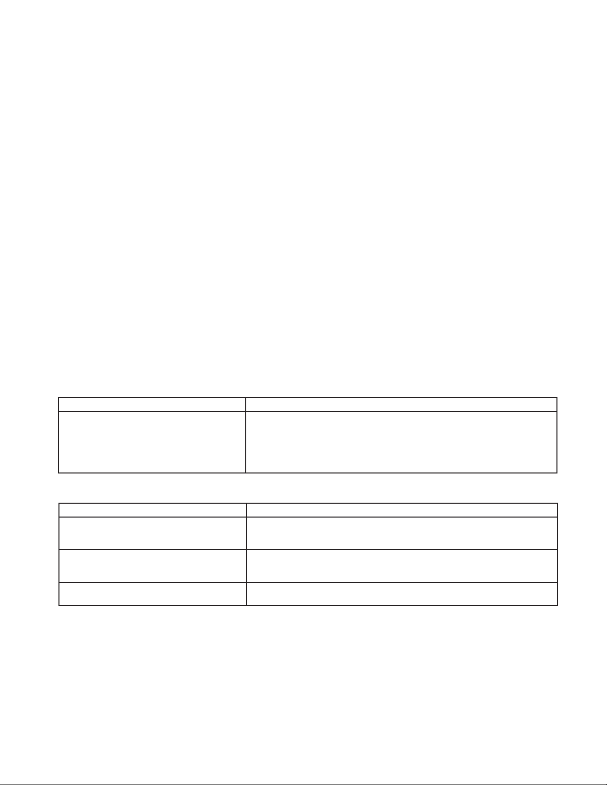
1. Erratic operation; chattering.
Possible Causes Remedies
A. Oversized regulator; inadequate rangeability. A1. Check actual flow conditions, re-size regulator for minimum and maximum flow.
A2. Increase flow rate.
A3. Decrease regulator pressure drop; decrease inlet pressure by placing a throttling
orifice in inlet piping union.
A4. Install next step higher range spring.
A5. Before replacing regulator, contact factory.
2. Regulator inlet (upstream) too high.
Possible Causes Remedies
A. Regulator undersized. A1. Confirm by opening bypass valve together with regulator.
B. Incorrect range spring (screwing in CW of
adjusting screw does not allow bringing
pressure level up to proper level).
C. Too much rise (build). C1. Review rise (build) expected.
4
A2. Check actual flow conditions, re-size regulator; if regulator has inadequate
capacity, replace with larger unit.
B. Replace range spring with proper lower range.
C2. Contact factory.
IOM-B7
Page 5
SECTION VIII
VIII. ORDERING INFORMATION
NEW REPLACEMENT UNIT vs PARTS "KIT" FOR FIELD REPAIR
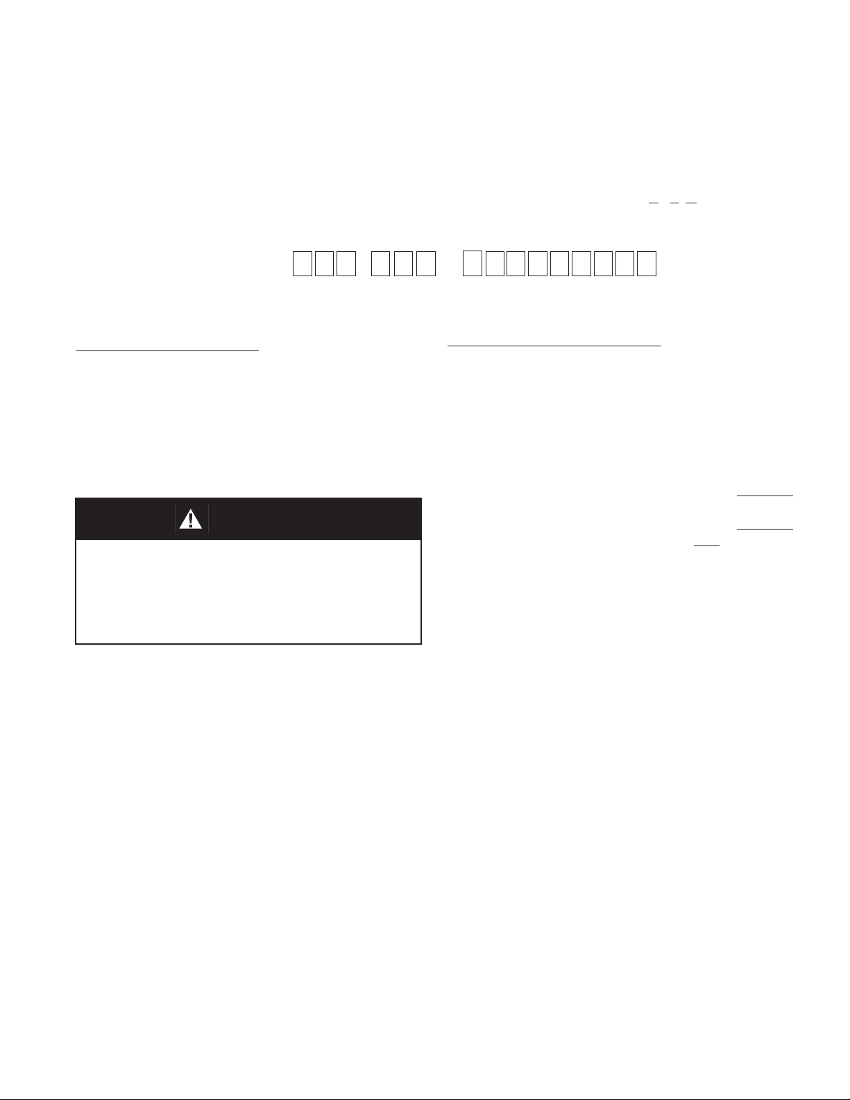
To obtain a quotation or place an order, please retrieve the Serial Number and Product Code that was stamped on
the metal name plate and attached to the unit. This information can also be found on the Bill of Material ("BOM"),
a parts list that was provided when unit was originally shipped. (Serial Number typically 6 digits). Product Code
typical format as follows: (last digit is alpha character that reflects revision level for the product).
–
NEW REPLACEMENT UNIT:
Contact your local Cashco, Inc., Sales Rep re sen ta tive with the Serial Number and Product code.
With this information they can provide a quotation
for a new unit including a complete description,
price and availability.
CAUTION
Do not attempt to alter the original construction
of any unit without assistance and approval from
the factory. All purposed changes will require a
new name plate with appropriate ratings and new
product code to accommodate the recommended
part(s) changes.
–
7
PARTS "KIT" for FIELD REPAIR:
Contact your local Cashco, Inc., Sales Rep re sen ta tive with the Serial Number and Product code.
Identify the parts and the quantity required to repair
the unit from the "BOM" sheet that was provided
when unit was originally shipped.
NOTE: Those part numbers that have a quantity indicated
under "Spare Parts" in column "A” reflect minimum
parts required for inspection and rebuild, - "Soft
Goods Kit". Those in column “B” include minimum
trim replacement parts needed plus those "Soft
Goods" parts from column "A".
If the "BOM" is not available, refer to the crosssectional drawings included in this manual for part
identification and selection.
A Local Sales Representative will provide quotation
for appropriate Kit Number, Price and Availability.
The contents of this publication are presented for informational purposes only, and while every effort has been made to ensure their accuracy, they are not to be
construed as warranties or guarantees, express or implied, regarding the products or services described herein or their use or applicability. We reserve the right to
modify or improve the designs or specifi cations of such product at any time without notice.
Cashco, Inc. does not assume responsibility for the selection, use or maintenance of any product. Responsibility for proper selection, use and maintenance of any
Cashco, Inc. product remains solely with the purchaser.
IOM-B7
5
Page 6
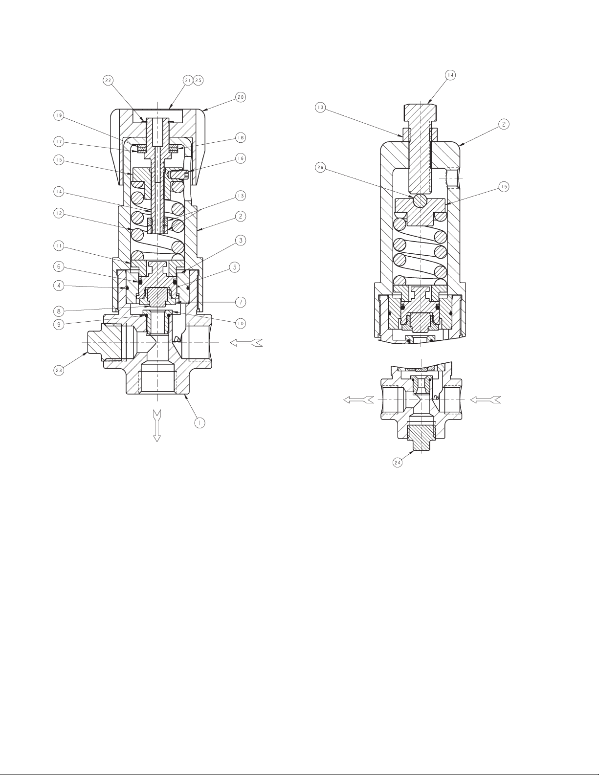
Figure 1
Angle Design
Repair Parts
Item No. Description
1 Body
2 Spring Chamber
3 Sleeve
4 Sleeve O-ring ‡‡
5 Piston
6 Piston O-ring ‡‡
7 Seat Retainer
8 Seat ‡‡
9 Orifi ce O-ring ‡‡
10 Orifi ce ‡‡
11 Spring Follower
12 Range Spring
13 Nut
Cashco, Inc.
P.O. Box 6
Ellsworth, KS 67439-0006
PH (785) 472-4461
Fax. # (785) 472-3539
www.cashco.com
email: [email protected]
Printed in U.S.A. B7-IOM
Cashco GmbH
Handwerkerstrasse 15
15366 Hoppegarten, Germany
PH +49 3342 30968 0
Fax. No. +49 3342 30968 29
www.cashco.com
email: [email protected]
Kit B
Cashco do Brasil, Ltda.
Al.Venus, 340
Indaiatuba - Sao Paulo, Brazil
PH +55 11 99677 7177
Fax. No.
www.cashco.com
email: [email protected]
Globe Design
Repair Parts
Item No. Description
14 Adjusting Screw
15 Spring Button
16 Set Screw
17 Thrust Button
18 Thrust Bearing
19 Thrust Washer
20 Knob
21 Knob Cover
22 Snap Ring
23 Plug
24 Plug
25 Decal
26 Ball
‡‡ Recommended Spare Part
Kit B
 Loading...