

Page 1
INSTALLATION, OPERATION & MAIN TE NANCE MANUAL (IOM)
MODELS 988 and 989
GLOBE-STYLE PNEUMATIC CONTROL VALVE BODY
SECTION I
I. DESCRIPTION AND SCOPE
Model 988’s and 989’s are pneumatically actuated, globestyle control valves. Sizes are 3/4", 1", 1-1/2" and 2". Ma te ri als are available in cast carbon steel, Grade WCB (CS);
cast 316L SST, Grade CF3M (SST); and cast CW-12MW,
sim i lar to Hastelloy C (H-C).
Failure position is determined by actuator for:
"D" = Direct action; on increasing air loading pressure, the
actuator stem extends. Fail-safe position is with the stem
retracted.
"R" = Reverse action; on increasing air loading pressure, the
actuator stem retracts. Fail-safe position is with the stem
extended.
IOM-988/989
12-13
These valves are designed for chemical service and most
com mon liquid, gaseous, or steam services.
Models 988 and 989 differ only in the face-to-face di men sions of fl anged units; 988’s have a “regular” (“long”) body
pattern, and the 989’s have a “short” body pattern.
II. REFERENCE
Refer to Technical Bulletin 988-TB or 989-TB for complete
tech ni cal specifi cations coupled with either Cashco Actuator
Model C27 or C53.
www.cashco.com/techbulletins/988.pdf
www.cashco.com/techbulletins/989.pdf
Refer to following Installation, Operation & Main te nance
Manuals (IOM’s) for either actuator and/or devices that
maybe mounted to a Model 988 or 989:
Actuators: www.cashco.com/IOM/C27-C53.pdf
Positioners:
P/P: www.cashco.com/techbulletins/9540l.pdf
I/P: www.cashco.com/techbulletins/srd991.pdf
I/P: www.cashco.com/iom/PS2iom.pdf
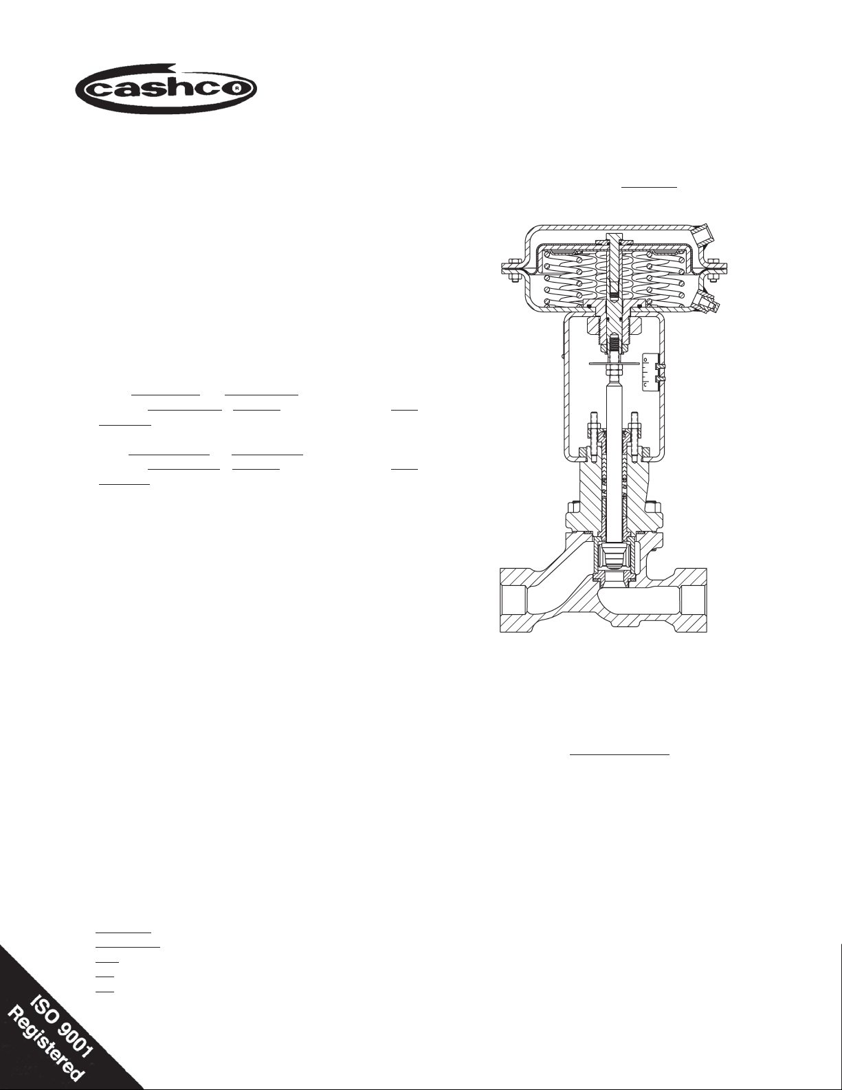
Model 988
with ATC - FO Actuator
Shown with Internal Live-Loaded Packing
SECTION II
ABBREVIATIONS
ATO-FC ............. Air-to-Open, Fail Closed
ATC-FO ............. Air-to-Close, Fail Open
CCW .................. Counter Clockwise
CW ..................... Clockwise
D or DIR ............. Direct Acting
HC ..................... Cast CW-12MW or Wrought Hast C-22
IAS ..................... Instrument Air Supply
LOAD ................. Positioner Output Air Pressure
R or REV ........... Reverse Acting
SIG .................... Output Signal from Instrument
SST.................... Cast or Wrought 316L Stainless Steel
V ........................ Vent
Page 2

SECTION III
III. INSTALLATION
A. Orientation:
1. Recommended orientation when installed in a hor i zon tal pipe line is with the stem vertical. Valves may
also be installed in vertical pipelines with stems
horizontal.
2. Outdoors, all installations may be oriented any
an gle from horizontal-to-vertical. (Orient actuator
vent cap, if supplied, to not collect rainwater that
might freeze.)
3. Model 988/989 valves with actuators are not rec om mend ed for installation with the actuator ori ent ed
down wards.
B. Piping System:
1. It is recommended that the control valve unit be in stalled with a double-block and bypass as in di cat ed
in Figure 1. This arrangement is rec om mend ed
especially where maintenance will be done on the
valve body while still installed in the pipe line.
4. For split-ring fl anged end connections, install fl ange
bolting to following torque values.
Recommended Maximum Flange Bolting Torque (ft-lbs.)
Body Size Body Material 150# Flange 300# Flange
3/4"
1" 29 36
1-1/2" 43 43
2" 66 33
3/4"
1" 24 30
1-1/2" 36 36
2" 54 27
3/4"
1" 32 40
1-1/2" 48 48
2" 72 36
CS
SST
HC
23 28
19 25
26 32
5. Clean piping of all foreign debris, including chips,
weld scale, weld spatter, oil, grease, sand or dirt
prior to in stall ing the control valve. This is an ab so lute re quire ment for valves supplied with com po si tion soft seats. System startup strain ers for re mov al
shortly after initial startup are rec om mend ed.
Figure 1: Typical Control Valve Station
2. Pipe unions are recommended for NPT screwed
or sock et welded installations to allow complete
re mov al from sys tem. If removal for maintenance
is by cutting torch for socket welded valves, leave
suffi cient pipe nipple space between the body and
the next piping component up or downstream to
allow socket weld couplings for re in stal la tion.
3. If pipe reducers are located before and/or after the
valve body, keep the reducers as close as prac ti cal
to the valve body; this is especially important where
the re duc ers are more than one line size larger than
the valve body size, which is common in gaseous
service.
6. Field hydrostatic testing the completed piping
sys tem to 1-1/2 x CWP in psig indicated on the
name plate including the Mod el 988/989 is acceptable. If hydro test pressure exceeds the 1-1/2
x CWP limit, the 988/989 must be removed for
such testing. Be fore pressurization, the valve plug
should be lifted from the seat if of reverse, ATO-FC
action. Tighten packing as required.
7. In placing thread sealant on pipe ends prior to en gage ment, ensure that excess material is re moved
and not allowed to enter the valve upon startup.
8. Flow Direction: Install so the fl ow direction match es
the arrow on the valve body.
9. For best performance, install in well drained
hor i zon tal pipe, properly trapped if a steam service
ap pli ca tion.
10. Valves are not to be direct buried underground.
11. Insulation may be applied as indicated in Figure
2. Drain age away from the packing area must be
en sured when fully in stalled, sealed and lagged for
outdoors in stal la tion.
12. Undue piping stress/strain or bending torques may
not be transmitted through the control valve body.
One pipe (inlet or outlet) should be anchored rig id ly for piping that is “hot” or “cold” with respect to
ambient temperature; the re main ing pipe (inlet or
outlet) should be supported and guid
ed to ensure
unidirectional expansion/contraction.
2
IOM-988/989-BODY
Page 3

IV. STARTUP
C. Removal From Piping System:
1. Care should be taken in removal of separable
fl anged units. Run wire in 180° crossing pattern
through bolt holes to prevent fl anges from coming
loose during handling.
CAUTION
Exhibit care in handling fl anged units to prevent sep a ra ble
fl ang es from coming loose, falling to fl oor and smashing
feet/toes.
Figure 2: Body Insulation
SECTION IV
A. General:
1. Ensure that the Model 988/989 unit has been
prop er ly ad just ed and calibrated, including the
positioner if in stalled.
2. Recommend startup to be in a “manual” mode.
This pro ce dure assumes double block (iso la tion)
and bypass valves for the “control valve sta tion”.
See Figure 1.
3. Start with either of the two block valves closed,
with the oth er open. The bypass valve should be
closed. Pressurize sys tem if possible/practical.
4. Back out the airset’s adjusting screw until loose.
5. Turn on air supply pressure.
6. Adjust the air supply airset (fi lter-regulator) to the
prop er lev el as indicated as follows:
Bench Setting Airset Output
psig (Barg) psig (Barg)
5–15 (.34–1.0) 20 (1.4)
7. Place loop controller into “manual” mode. Vary
8. Confi rm that action of controller and positioner
15–60 (1.0–4.1) 75 (5.2)
set ting from minimum – mid-range – max i mum
SIG out put. Observe re sponse of con trol valve unit
to these chang es of in put SIG. The valve should
fully stroke at the vari a tion from min i mum SIG to
max i mum SIG; the mid-range SIG should have the
valve stem travel at/near 1/2 open.
– direct or reverse – are pro duc ing the desired re sponse in the con trol unit. Confi rm that the control
valve “fail” po si tion is as required.
CAUTION
DO NOT WALK AWAY AND LEAVE A MANUALLY CON TROLLED CONTROL VALVE UNATTENDED!
9. Hereafter, the procedure assumes that actual fl u id
fl ow may be established. This may not be prac ti-
cal/pos si ble in all cas es; if so, vary procedure as
re quired. Always “heat” or “cool” down the system
piping SLOW LY by open ing the control valve sta tion by pass valve in small increments.
10. With one of the control valve station block valves
still closed, and the loop controller still in “manual”
mode, open by pass valve and vary fl ow rate man u-
al ly to observe the response of the con trol ler and
control valve unit to geth er.
11. Attempt to develop manual control of the loop by
open ing/closing the manual bypass as re quired,
or by manually con trol ling mainstream fl ow as
re quired.
12. When the control valve is partially open, slowly
crack open the closed block valve while si mul ta neous ly closing the bypass valve. Continue this
pro ce dure until the bypass is closed and the block
valves are both fully open. The system is still un der “man u al” mode control, but all fl ow is pass ing
through the control valve.
13. Vary controller “manual” SIG output until match ing
the “au to mat ic” SIG output, then change the mode
of the controller over to “automatic”. The loop will
ex pe ri ence a minimum of upset conditions, and will
be in au to matic control.
IOM-988/989-BODY
3
Page 4

SECTION V
B. Actuator Assembly Removal:
WARNING
SYSTEM UNDER PRESSURE. Prior to performing any
main te nance, isolate the valve/actuator from the system
and re lieve all pressure. Failure to do so could result in
personal in ju ry.
V. MAINTENANCE
A. General:
1. Maintenance procedures hereinafter are based
upon re mov al of the valve/actuator unit from the
pipeline where in stalled.
2. Owner should refer to Owner’s procedures for
re mov al, han dling and cleaning of non-reusable
parts, i.e. gaskets, suit able solvents, etc.
3. Valves supplied from the factory do not use any
aid to assist in gasket sealing such as oil, sealant
or pipe dope. Owner may use such aids provided
the aids are com pat i ble with the Owner’s fl uid.(See
below for “oxygen cleaned” valves.)
4. Valves originally supplied per Option-55 require
special clean ing procedures. Refer to Cashco
Spec i fi ca tion No. S-1134 for details. When in
com pli ance with/to Spec. No. S-1134, the valve
is suit able for oxygen service. This procedure is
limited to bodies of SST or HC only.
5. All indicated Item Numbers that are with respect to
the actuator assembly (AA) will be in parenthesis
and un der scored; i.e. (20); All Item Numbers that
are with respect to the body assembly (BA) are not
underscored; i.e. (32).
6. Special care must be exhibited when rotating
the plug/stem (3) of the valve to not mar that portion of the surface of the stem where it contacts
with the packing (6). To rotate the plug/stem use
the jam nuts (52) or a soft jawed pliers. NOTE:
When using the jam nuts to rotate the plug/stem,
use the upper jam nut to rotate the stem CW, and
the lower jam nut to rotate the stem CCW, when
viewed from above valve plug/stem.
7. Hereafter, whenever text has the following notation,
"
(Note PA.)", the following text is to be applied:
1. Refer to the correct actuator IOM for this pro ce dure.
2. Secure the (BA) in a vise with the (AA) oriented
vertically.
3. Rig (AA) to be supported above the (BA). Place
matchmarks between the bonnet/yoke and yoke/
ac ces so ry plate.
4. This procedure assumes that the (BA) is fully
assembled through the bonnet (2), in clud ing the
pack ing fl ange (4), fol low er (5), and packing (6).
5. (Note PA.)
stem (6) by wrench, loos en stem jam nuts (52) by
rotating CW (viewed from above) one-at-a-time.
6. Fully loosen any accessory devices that are con nect ed to/with the stems (6), (3), such as ac ces so ry
plate ((AP)) for limit switch or positioner. If actuator
has handwheel - see Actuator IOM for removal
instructions.
7. Using a blunt end tool, hammer rap the tool to
loos en yoke nut (25), turning CCW (viewed from
above) approximately 1/2 revolution.
8. If the actuator is to be reinstalled, put paint or dye
mark er between the plug/stem (3) and the ac tu a tor
stem (6), to serve as matchmarks.
9. Loosen packing (6) by rotating nuts (15) CCW 2-3
revolutions. (Note RP).
NOTE: To fully disengage the actuator stem (6)
from the plug/stem (3) is a two-step procedure. Be
aware of the valve’s stroke length as indicated on
the name plate (40) before beginning dis en gage ment. During the dis en gage ment, measure the
distance ex tend ed and attempt to make each step
about half of full stroke. Keep track of the num ber
of rev o lu tions for each step in the box below.
For Steps 10A and 10B: Count the Number
of revolutions to disengage plug/stem from actuator stem:
Step A. __________ Step B. _________
TOTAL ________
Securing the “fl ats” of the actuator
"For ATO-FC units ONLY, connect a tempo-
10A. For ATO-FC Reverse Action Actuators:
rary air source with gauge to the actuator
and pressurize to a level suffi cient to initi-
ate travel to approximately mid-stroke."
8. Hereafter, whenever text has the following
notation, "(Note RP.)", the following text is to
be applied:
"For ATO-FC units ONLY, release all tem-
a. (NOTE PA).
b. Step A. Rotate plug/stem (3) CW (viewed from
above the valve) to disengage the actuator
stem from the plug/stem. Record number of
plug/stem revolutions for Step A in box above.
When dis en gage ment reaches ap prox i mate ly
50% of full stroke travel, Step A is complete.
porary air pressure."
4
IOM-988/989-BODY
Page 5

c. Step B. Support the (AA) from above. Fully
loosen yoke nut (25) to re mov al. Lift the (AA)
up wards approximately 1/4"–3/8" (6–8 mm).
Again, ro tate plug/stem (3) CW (viewed from
above) until dis en gage ment from actuator
stem (6). Record num ber of plug/ stem revolutions for Step B in box on previous page.
NOTE: Take notice of the parts “dangling loosely”
about the stem, the order of their location and their
proper orientation.
d. Fully raise (AA) above (BA). Remove carefully
to prevent "dangling parts" (position indicating
washer (51), accessory plate ((AP)), yoke nut
(25)) from falling.
(Note RP).
6. Lower (AA) until the opening of the ac tu a tor yoke
(3) is at the level of upper jam nut (52).
7. Place yoke nut (25) over the plug/stem (3) and
lower the nut to rest upon the yoke.
8. Place travel indicator washer (51) and accessory
plate ((AP)) over stem (3) and allow to rest upon
upper stem jam nut (52).
9. Align matchmarks between body/bonnet, bonnet/
yoke and yoke/accessory plate. Continue to lower
(AA) until two stems are approximately 3/8" (8mm)
apart.
10. Ensure that plug/stem (3) is resting on seat ring.
10B. For ATC-FO Direct Action Actuators:
a. Step A. Rotate plug/stem (3) CW (viewed
from above the valve) to disengage the actuator stem from the plug/stem. Record number
of plug/stem revolutions for Step A in box on
previous page When dis en gage ment reach es
ap prox i mate ly 50% of full stroke travel, Step
A is completed.
.
b. Step B. Support the (AA) from above. Fully
loosen yoke nut (25) to re mov al. Lift the (AA)
up wards approximately 1/4"–3/8" (6–8 mm).
Again ro tate plug/stem (3) CW (viewed from
above valve) until dis en gage ment from ac tu a-
tor stem (6). Record the num ber of valve stem
rev o lu tions for Step B in box on pre vi ous page.
NOTE: Take notice of the parts “dangling loose ly”
about the stem, the order of their location and their
proper orientation.
c. Fully raise (AA) above (BA). Remove care-
fully to prevent “dan gling parts” (position indicating
washer (51), ac ces so ry plate ((AP)), yoke nut (25)
from falling.
C. Mounting Actuator Assembly to Body As sem bly:
1. Refer to the correct actuator IOM for completion of
this pro ce dure.
2. Secure the (BA) in a vise with the plug/stem (3)
oriented vertically. Push stem down until plug
touches the seating surface in the body.
3. Rig (AA) to be supported above the (BA).
4. This procedure assumes that the packing assembly
and bonnet (2) have been bolt ed to the body (1).
5. Engage stem jam nuts (52) one-at-a-time to the
plug/stem (3) by rotating CW (viewed from above
stem end). Rotate jam nuts all the way down to the
root of the stem threads.
11A. For ATC-FO: Hook up a temporary air supply
hose that has an ad just able airset connected at
the actuator inlet to allow pres sur iza tion. Slowly
pres sur ize ac tu a tor to bring the actuator stem to
within 1/8" (3mm) of touching the plug/stem.
11B. For ATO-FC: Continue lowering (AA) un til ac tu a-
tor’s stem (6) and valve’s stem (3) almost touch.
12. Rotate yoke nut (25) onto bonnet (2) threads as far
as able to help stabilize topworks. Wrench-tighten
one-half (1/2) extra rev o lu tion.
13. Use hand to lift plug/stem (3) upwards to engage
with actuator stem (6). Ro tat ing plug/stem CW
(viewed from plug end) the same number of rev o lu tions recorded to dis en gage the stem per B Step
10A.
14. For ATC-FO: Release air pressure from (AA).
For ATO-FC: (NOTE PA).
15. Fully lower the (AA) down wards un til the yoke (3) is
properly positioned on the valve bon net (2). Handtighten yoke nut (25).
16. Complete the engagement of plug/stem into the
ac tu a tor stem the same number of revolutions
re cord ed to disengage the stems per B Step 10B.
(NOTE RP)
17. Connect “dangling parts” – accessory plate (AP)
and travel indicator disc (51) – to actuator stem (6)
with stem jam nuts (52).
18. Retighten packing fl ange nuts (15).
19. Hammer rap yoke nut (25) with a blunt end tool
until tight.
20. Check valve stem stoke by alternately pressurizing and then de pres sur iz ing the actuator. Repeat
several times. DO NOT OVER PRES SUR IZE.
21. Release all air pressure from (AA) and re move
temporary air supply hook up.
IOM-988/989-BODY
5
Page 6

D. Trim and Packing Removal and Replacement for
Units with Internal Live-Loaded Packing; Opt-STD
or Opt-KRI: (See pg. 19 for Item # identifi cation.)
1. Remove (AA) as described in Sub-Sec tion V.B.
Leave (BA) in vise with plug/stem (3) upwards.
14. Examine plug/stem (3) in critical fi nish zone where
con tact is made with the packing (6). It is desirable
to re store the surface of the stem (3) to a #4 Ra μ-in
surface fi nish; metal removal should not exceed
0.001 inch material. A deeply scratched or pitted
stem should be replaced.
2. Continue to loosen stem packing (6) by rotating
pack ing nuts (15) CCW to just short of disengagement from packing studs (14). DO NOT REMOVE
PACKING NUTS (15).
3. Remove all bonnet stud nuts (17).
4. Lift bonnet (2), plug/stem assembly (3), cage (10)
and all packing zone parts up and out of the body
- grasp stem (3) to prevent from falling. Lay these
parts down horizontally on a workbench. NOTE:
Seat ring (11) (and seat retainer (23) and soft seat
insert (24) for com po si tion/soft seated de signs)
may also pull out with the above parts assembly.
5. Remove both stem nuts (52).
6. Withdraw plug/stem (3) out through bottom of the
bon net (2) and packing (6). Hold cage (10) to
pre vent from dropping. Set parts (3, 10) aside.
7. Place bonnet (2) into a second vise with the pack ing
zone on top.
8. Remove the packing nuts (15).
9. Remove packing fl ange (4) and fol low er (5).
CAUTION
Take extreme care to not mar internal wall surface of the
bonnet (2).
10. Using a sharp, hooked-end, pick-type tool, hook and
pull the packing rings (6) up and out of the bon net’s
(2) stuffi ng box in di vid u al ly. Examine for excessive
wear. Discard old pack ing.
11. Remove bonnet (2) from vise and invert to al low
pack ing washer (7), packing spacer (9) and pack ing
spring (21) to slide out of the bonnet’s stuffi ng box.
12. Solvent clean all parts to be reused, including bon net (2). Examine any parts for wear and cor ro sion.
Replace any corroded or warn parts.
15. Examine plug/stem (3) for wear around the seating
area. Ex am ine seat ring (11).
a. Plug head of stem assembly (3) for metal
seat ed design may be hand lapped using
suit able lap ping compound. If hand lapping will
not re store sur fac es to an acceptable de gree,
then re place ment of plug/stem assembly is
rec om mend ed.
b. For composition seated design, if plug/stem
as sem bly is wear damaged, the stem should
be re placed.
16. Examine the inner surface of the bonnet’s (2)
stuffi ng box. It is desirable to restore the surface
of stuffi ng box to a #8 Ra μ-in surface fi nish; metal
re mov al should not exceed 0.001 inch material. A
deep ly scratched or pit ted bon net (2) should be
replaced.
17. Examine packing follower (5) for corrosion. Re place if corroded:
a. Replace follower bushing (26) with new bush-
ing.
b. Replace wiper ring (22) with new wiper ring.
18. Turn attention to the body (1) and remaining parts
yet there in. Remove seat ring (11) (and seat re tain er (23) and soft seat in sert (24) for com po si tion/
soft seated de sign) if not already removed. Discard
used soft seat in sert (24); always use a new soft
seat insert upon re as sem bly. If seat ring (11) or
seat retainer (23) are damaged, replace.
19. Examine gaskets (12,13) to see if leakage oc curred. Re move and discard both the seat ring
gasket and bonnet gas ket. Always use new gaskets
upon reassembly.
20. Remove body (1) from vise. Solvent clean all loose
parts with suitable solvent. Determine parts to be
re placed due to wear and/or corrosion. Clean seat
ring (11), cage (10), and seat re tain er (23).
21. Place body (1) into vise with body/bonnet fl ange
face up.
22. Place a new seat ring gasket (13) into position.
13. Examine plug/stem (3) at lower guide bushing (8)
area for wear. If there are signs of ex cess wear,
guide bushing (8) should be replaced:
a. Place the bonnet (2) on a bench press. Press
the guide bush ing (8) out of the bonnet and
discard.
b. Rotate bonnet (2) end-for-end. Place a new
guide bush ing (8) into position and press fully
into the bonnet.
c. Reclean bonnet with suitable solvent.
6
23. Note correct orientation of seat ring (11) and place
inside the body (1).
24. For composition/soft seat design, position a new
soft seat insert (24) and the seat retainer (23) into
position on top of seat ring (11).
25. Place new bonnet gasket (12) on the body’s bonnet
fl ange face.
IOM-988/989-BODY
Page 7

26. With the cage (10) oriented correctly on the stem
assembly (3), set plug head down into the seat
ring (11). Keep fi rm hold of the plug/stem with
one hand; use other hand to push cage down into
proper alignment.
27. Lift bonnet (2) over threaded end of plug/stem
(3) and care ful ly lower bonnet down over stem,
en sur ing that the crit i cal fi nish zone of the bonnet’s
stuffi ng box is not scratched by the stem’s threads.
Align body (1)-to-bonnet (2) fl anges to matchmarks
as bonnet comes down over bon net studs (16).
Carefully release plug/stem (3) only when bonnet
is completely resting on the body.
37. Install packing stud nuts (15), fi nger-tight, on top
of the pack ing fl ange (4).
38. Continue tightening nuts (15) evenly in 1/2 revolution in cre ments, until the shoulder of packing
fol low er (5) is resting evenly on the upper edge of
the bonnet (2) at the stuffi ng box.
39. Thread the two stem jam nuts (52) onto the stem (3)
and rotate as far down the plug/stem as possible.
40. Push valve stem (3) down into the seat ring (11).
Wig gle the loose assembly to ensure initial align ment/stack ing.
28. Install bonnet nuts (17) onto bonnet studs (16) and
fi n ger-tighten.
29. Place packing spacer (9) over end of plug/stem (3)
and care ful ly lower into stuffi ng box.
30. Place packing spring (21) over end of plug/stem
(3) and care ful ly lower down into stuffi ng box.
Figure 3: “STD” and “KRI” Packing Orientation
31. Place packing washer (7) over end of plug/stem (3)
and care ful ly lower into stuffi ng box. See Figure 3
for proper packing ori en ta tion.
32. Carefully place lower adapter (6.3) of packing ring
set (6) over plug/stem’s (3) end, properly oriented.
Us ing the packing follower (5), push the lower
adapt er into the bonnet’s (2) stuffi ng box.
33. Carefully place a packing ring (6.2) properly ori ent ed over the plug/stem’s (3) end and push into
the stuffi ng box similar to the adapter (6.3). Re peat
for each of the four rings (6.2).
34. Place upper adapter (6.1) over the stem 3)
35. Place packing follower (5) with new wiper ring (22)
and new follower bushing (26) tape over the end
of the plug/stem (3).
36. Place packing fl ange (4) over end of plug/stem (3)
and over pack ing studs (14).
41. Tighten bonnet bolting (16,17) in an alternating
cross-pat tern in 1/4 revolution increments to the
following torque lev els:
Size Torque
3/4”, 1”, 1-1/2” 70-75 ft-lbs (95-102 N-M)
2” 50-55 ft-lbs (68-75 N-M)
42. Reinstall the (AA) as recorded in Sub-Section V.C.
43. Position suitable end closures – plugs, blind fl ang es,
etc., – and leak test with 100 psig air pres sure
min i mum. No packing (6) adjustment should be
re quired to get a tight seal.
44. Recalibrate per Section VI.
E. Trim and Packing Removal and Replacement for
Units With External Live-Loaded Packing; Opt-EXT,
Opt-KRE, Opt-HTE-Hi, or Opt-HTE-Lo: (See pg. 20
for Item # identifi cation.)
WARNING
Failure to ensure proper release of forces from Belleville
spring washers can cause fl ying parts that might cause
bodi ly injury.
1. Remove (AA) as described in Sub-Sec tion V.B.
Leave (BA) in vise with plug/stem (3) upwards.
2. Place thread penetrating lubricant on bonnet bolt ing (16,17) and packing bolting (14,15).
3. Loosen both packing stud nuts (15) until clearance
ex ists be tween the bottom of the nuts (15) and the
upper retainers (39). See Fig ure 4.
4. Spacer rings (40) should “spin freely”. If stacked
mech a nism (39,40,41) is not “loose” due to cor ro sion, de bris, packed dirt, etc., tap the spacer rings
lightly with a hammer while at tempt ing to pry up
the spacer ring /lower retainer with a fl at tool. DO
NOT REMOVE PACK ING NUTS (15).
5. Continue to loosen pack ing stud nuts (15) to just
short of dis en gage ment from packing studs (14).
DO NOT RE MOVE PACKING NUTS.
IOM-988/989-BODY
7
Page 8

Figure 4: External Live Loaded Packing Orientation
6. Remove all bonnet stud nuts (17).
15. Solvent clean all parts to be reused including bon net (2). Examine all parts for wear and corrosion.
Re place any cor rod ed or worn parts. Belleville
spring wash ers (41), studs (14,16), nuts (15,17)
and retainers (39) should be replaced in sets.
16. Examine plug/stem (3) at lower guide bushing area
(8) for wear. If there are signs of excess wear, guide
bushing should be replaced:
a. Place the bonnet (2) on a bench press. Press
the guide bush ing (8) out of the bonnet and
dis card.
b. Rotate bonnet (2) end-for-end. Place a new
guide bush ing (8) into position and press fully
into the bonnet.
c. Reclean bonnet with suitable solvent.
17. Examine plug/stem (3) in critical fi nish zone where
con tact is made with the packing (6). It is desirable
to re store the surface of the stem to a #4 Ra μ-in
surface fi nish; metal removal should not exceed
0.001 inch material. A deeply scratched or pitted
stem should be replaced.
7. Lift bonnet (2), plug/stem assembly (3), cage (10),
and all pack ing zone parts up and out of the body
(1) - grasp stem to prevent from falling. Lay these
parts down horizontally on a workbench. NOTE:
Seat ring (11) (and seat retainer (23) and soft seat
insert (24) for composition/soft seated de signs)
may also pull out with above parts assembly.
8. Remove both stem nuts (52).
9. Withdraw plug/stem assembly (3) from within the
bon net (2) and packing (6). Hold cage (10) to
pre vent from dropping. Set parts (3,10) aside.
10. Place the bonnet (2) into a second vise with the
pack ing zone on top. Remove packing nuts (15).
11. Grasp the lower retainers (39) from its underneath
side and lift the lower retainers, spacer rings (40),
Belleville spring wash er stacks (41), and upper
re tain ers(39) together up and over the packing
studs (14). Set these parts (39,40,41) aside without
disturbing the orientation.
12. Remove packing follower (5) together with fol low er
bush ing (26 or 5.2). Discard Rulon tape bushing
(26) if supplied.
CAUTION
Take extreme care to not mar internal wall surface of the
bonnet (2).
13. Using a sharp, hooked-end, pick-type tool, hook
and pull the packing rings (6) up and out of the
bonnet’s (2) stuffi ng box individually. Examine for
excessive wear. Discard pack ing.
14. Remove bonnet (2) from the vise and invert to al low packing spacer (9) to slide out of the bonnet’s
stuffi ng box.
18. Examine plug/stem (3) for wear around the seating
area. Ex am ine seat ring (11).
a. Plug head of stem assembly (3) of metal
seat ed design may be hand lapped using
suit able lap ping compound. If hand lapping will
not re store sur fac es to an acceptable de gree,
then re place ment of plug/stem assembly is
rec om mend ed.
b. For composition seated design, if plug/stem
as sem bly (3) is wear damaged, the stem (3)
should be re placed.
19. Examine inner surface of the bonnet’s (2) stuffi ng
box. It is desirable to restore the surface of stuffi ng
box to a #8 Ra μ-in surface fi nish; metal re mov al
should not exceed 0.001 inch ma te ri al. A deeply
scratched or pitted bonnet (2) should be re placed.
20. Examine packing follower (5) for corrosion. Re place if sig nifi cant ly corroded:
a. Place new follower bushing tape (26) into fol-
low er’s (5) interior groove.
b. If packing Opt-HTE-Hi or Opt-HTE-Lo is sup-
plied, the pack ing follower (5) contains carbon
bushing (5.2) that is pressed into the fol low er
(5.1). This bushing (5.2) is not fi eld re place-
able and must be supplied as a packing fol low er sub-assembly (5). Ex am ine the car bon
bush ing (5.2) for wear or cor ro sion. Re place
follower sub-as sem bly when nec es sary.
21. Turn attention to the body (1) and the remaining
parts yet therein. Remove seat ring (11) (and seat
retainer (23) and soft seat insert (24) for com po si tion/soft seated design). Discard used soft seat
in sert (24); always use a new soft seat insert upon
reassembly, If seat ring(11) or seat retainer (23)
are dam aged, replace.
8
IOM-988/989-BODY
Page 9

22. Examine gaskets (12,13) to see if leakage oc curred. Re move and discard both gas kets. Always
use new gaskets upon reassembly.
23. Remove body (1) from vise. Solvent clean all loose
parts with suitable solvent. Determine parts to be
replaced due to wear and/or corrosion. Clean seat
ring (11), cage (10), and seat re tain er (23).
24. Place body (1) into vise with body/bonnet fl ange
up. Install a new seat ring gasket (13) inside body
25. Note correct orientation of seat ring (11)and place
inside the body (1).
26. For a composition/soft seat design, position a new
soft seat inset (24) and the seat retainer (23) into
po si tion on top of seat ring (11).
27. Place a new bonnet gasket (12) on the body’s (1)
bon net fl ange face.
28. With the cage (10) oriented correctly on the stem
assembly (3), set plug head down into the seat ring
(11). Keep fi rm hold of the stem with one hand;
use other hand to push cage (10) down into proper
alignment.
29. Lift bonnet (2) over threaded end of plug/stem
(3) and care ful ly lower bonnet down over stem,
en sur ing that the crit i cal fi nish zone of the bonnet’s
stuffi ng box is not scratched by the stem’s threads.
Align body (1) to-bonnet (2) fl anges to matchmarks
as bonnet comes down over bon net studs (16).
Carefully release stem (3) only when bonnet is
completely resting on the body.
Figure 5: Belleville Spring Washers Orientation
g. Place upper retainers (39) over the pack ing
studs (14), and onto the ledge of the spac er
rings (40). Ensure the up per retainers (39) are
prop er ly po si tioned around its cir cum fer ence.
h. Install packing stud nuts (15), fi nger-tight, on
top of the upper re tain ers (39). (See Fig. 4.)
i. Ensure that nuts (15) are drawn down evenly
such that the upper retainers (39) are lev el.
Wrench tighten pack ing nuts in 1/2 rev o lu tion
increments. Con tin ue to tight en nuts until the
spacer rings (40) can no long er be manually
rotated by use of fi n gers; add 1/2 revolution of
additional draw-down to each nut to properly
load the packing (6).
32B. For Opt-HTE-Hi and Opt-HTE-Lo packing options
(Ref er to Fig. 6 for proper packing ori en ta tion) –
30. Install bonnet nuts (17) onto bonnet studs (16) and
fi n ger -tighten.
31. Place packing spacer (9) over end of plug/stem (3)
and care ful ly lower into stuffi ng box.
32A. For Opt-EXT and Opt-KRE Packing option – (Ref-
er ence Figure 3 for proper packing orientation) –
a. Carefully place lower adapter (6.3) of the new
packing ring set (6) over plug/stem’s (3) end,
properly ori ent ed. Using the packing follower
(5), push the low er adapter into bonnet’s (2)
stuffi ng box.
b. Carefully place a packing ring (6.2) properly
ori ent ed over the plug/stem’s end and push
into the stuffi ng box similar to the adapter (6.3).
Repeat for each of the four rings (6.2).
c. Carefully place upper adapter (6.1) similar to
low er adapter (6.3). Leave packing fol low er
(5) in po si tion, properly ori ent ed.
d. Place lower retainers (39) over each of the
packing studs (14). See Fig. 4 for proper orientation.
e. Orient spring washers (41) stacks per Figure
5. Low er spring washer stacks over studs and
down onto the lower retainers (39).
f. Place spacer rings (40) over studs and onto
ledge of lower retainers (39).
Figure 6: Packing Orientation for Opt-“HTE-Hi & Lo”
a. Carefully place the lower braided ring (6.4)
over the plug/stem’s (3) end. Using the packing
follower (5) push the lower braided ring (6.4)
into the bonnet’s (2) stuffi ng box.
b. Carefully place lower adapter (6.3) prop er ly
ori ent ed over the plug/stem's end and push
into the stuffi ng box similar to the lower braid ed
ring.
c. Carefully place a packing ring (6.2) properly
ori ent ed over the plug/stem’s end and push
into the stuffi ng box similar to the lower braided
ring . Repeat for each ring.
d. Carefully place the upper adapter (6.1) similar
to the lower adapter (6.3). Leave packing fol low er (5) in po si tion, prop er ly oriented.
e. Place one of the lower retainers(39) over each
of the packing studs (14). In stall pack ing nuts
(15) and fi nger-tighten.
IOM-988/989-BODY
9
Page 10

f. Wrench-tighten the packing stud nuts (15)
evenly and in 1/2 rev o lu tion increments until
the “up per groove on the packing fol low er (5),
iden ti fi ed as “Line A” (Fig. 4), is fl ush with the
top edge of the bonnet’s (2) stuffi ng box.
g. Remove the packing nuts (15), lower retainers
(39) and pack ing follower (5).
h. Carefully place the upper braided ring (6.4)
over the plug/stem’s (3) end and push into the
stuffi ng box similar to the lower braided ring
(6.4). Leave the packing follower in position,
prop er ly oriented.
i. Place lower retainers (39) over each of the
pack ing studs (14). Install packing stud nuts
(15) and fi nger-tighten.
j. Repeat Step f. with the exception that the
pack ing set (6) is to be compressed into the
stuffi ng box until the “lower groove” identifi ed
as “Line B” on the packing follower (5) is fl ush
with top edge of the bon net’s (2) stuffi ng box.
k. Remove the packing nuts (15). Leave the fol-
low er (5) and lower retainers in place.
l. Orient spring washer (41) stacks per Figure
5. Low er stacks over studs and onto ledge of
lower retainers (39).
m. Place spacer rings (40) over studs and onto
ledge of lower retainers (39).
n. Place upper retainers (39) over pack ing studs
(14), and onto the ledge of the spac er rings
(40). Ensure the up per retainers (39) are prop er ly po si tioned around its cir cum fer ence and
that the in ver sion is correct for HTE-Hi versus
HTE-Lo options.
o. Install packing stud nuts (15), fi nger-tight, down
to the upper re tain ers (39).
p. Manually stroke the plug/stem (3) a minimum
of fi f ty full strokes.
q. Ensure that packing stud nuts (15) are drawn
down such that the upper retainers (39) are
level with top of spac er rings (40). Wrenchtighten pack ing stud nuts in 1/2 revolution
increments. Con tin ue to tighten nuts until the
spacer rings can no longer be man u al ly rotated
by use of
tion al draw-down to each nut to properly load
the pack ing (6).
fi n gers; add 1/2 revolution of ad di-
37. Position suitable end closures – plugs, blind fl ang-
es, etc., – and leak test with 100 psig air pressure
min i mum. No packing (6) adjustment should be
re quired to get a tight seal.
38. Recalibrate per Section VI.
F. Trim and Packing Removal and Replacement for
Units with Jammed Packing; Opt-38J, Opt-34A, Opt34B, Opt-34C:(See pg. 11 & 19 for Item # identifi cation.)
1. Remove (AA) as described in Sub-Sec tion V.B.
Leave (BA) in vise with plug/stem (3) upwards.
2. Continue to loosen stem packing (6, 47) by rotating pack ing stud nuts (15) CCW to just short of
disengagement from packing studs (14).
3. Remove all bonnet stud nuts (17).
4. Lift bonnet (2), plug/stem assembly (3), cage (10)
and all packing zone parts up and out of the body
- grasp stem (3) to prevent from falling. Lay these
parts horizontally on a workbench. NOTE: Seat ring
(11) (and seat retainer (23) and soft seat insert (24)
for com po si tion/soft seated de signs) may also pull
out with the above parts assembly.
5. Remove both stem nuts (52).
6. Withdraw plug/stem assembly (3) from within the
bon net (2) and packing (6, 47). Holding cage (10)
to pre vent from dropping. Set parts (3, 10) aside.
7. Place bonnet (2) into a second vise with the pack ing
zone on top. Remove the two packing nuts (15).
8. Remove packing fl ange (4), packing follower (5),
wiper ring (22) and TFE bias tape follower bush ing
(26).
CAUTION
Take extreme care to not mar internal wall surface of the
bonnet (2).
10
33. Reinstall the two stem jam nuts (52) onto the plug/
stem (3) and rotate as far down the as possible.
34. Push valve stem (3) down into the seat ring (11).
Wig gle the loose assembly to ensure initial align ment/stack ing.
35. Tighten bonnet bolting (16, 17) in an alternating
cross-pat tern in 1/4 revolution increments to the
following torque lev els:
Size Torque
3/4”, 1”, 1-1/2” 70-75 ft-lbs 95-102 N-M)
2 50-55 ft-lbs (68-75 N-M)
36. Reinstall the actuator assembly (AA) as recorded
in Sub-Section V.C.
9. Using a sharp, hooked-end, pick-type tool, hook
and pull the packing rings (47) up and out of the
bonnet’s (2) stuffi ng box individually. Examine for
proper orientation (see Figures 7, 8, 9 and 10).
10. Remove bonnet (2) from vise and invert to allow
lantern ring (27) or packing spacer (9) to slide out
of the bonnet’s stuffi ng box.
For Opt-34 –
a. Invert bonnet (2) again and place back in vise
with pack ing zone on top.
CAUTION
Take extreme care to not mar internal wall surface of the
bonnet (2).
IOM-988/989-BODY
Page 11

Figure 7: Dual Packing – Arr. “A”, Opt-34A
b. Using a sharp, hooked-end, pick-type tool,
hook and pull the primary lower packing ring
set (6) up and out of the bon net’s (2) stuffi ng
box individually. Examine for proper ori en ta tion (see Fig ures 7, 8 and 9).
11. Solvent clean all parts to be reused, including
bon net. Examine any parts for wear and cor ro sion.
Re place any corroded or worn parts. Discard old
pack ing.
12 Examine plug/stem (3) at lower guide bushing (8)
area for wear. If there are signs of excess wear,
guide bushing should be replaced:
a. Place the bonnet (2) on a bench press. Press
guide bush ing out of bonnet and dis card.
b. Rotate bonnet end-for-end. Place a new guide
bush ing into position and press fully into the
bonnet.
c. Reclean bonnet with suitable solvent.
13. Examine plug/stem (3) in critical fi nish zone where
con tact is made with the packing (6,47). It is desirable to re store the surface of the stem to a #4
Ra μ-in surface fi nish; metal removal should not
exceed 0.001 inch material. A deeply scratched
or pitted stem should be replaced.
Figure 8: Dual Packing – Arr. “B”, Opt-34B
Figure 9: Dual Packing – Arr. “C”, Opt-34C
14. Examine plug/stem (3) for wear around the seating
area. Ex am ine seat ring (11).
a. Plug head of stem assembly of metal seat ed
design may be hand lapped using suit able
lap ping com pound. If hand lap ping will not
re store sur fac es to an ac cept able degree,
then re place ment of plug/stem assembly is
rec om mend ed.
b. For composition seated design, if stem as sem-
bly is wear damaged, the plug/stem should be
replaced.
15. Examine the inner surface of the bonnet’s (2)
stuffi ng box. It is desirable to restore the surface
of stuffi ng box to a #8 Ra μ-in surface fi nish; metal
re mov al should not exceed 0.001 inch ma te ri al. A
deeply scratched or pitted bonnet (2) should be
re placed.
16. Examine packing follower (5) for corrosion. Re place
if sig nifi
cant ly corroded:
a. Replace follower bushing (26) with new bush-
ing (26).
b. Replace wiper ring (22) with new ring (22).
17. Turn attention to the body and remaining parts yet
there in. Remove seat ring (11) (and seat re tain er
(23) and soft seat in sert (24) for com po si tion/soft
seated de sign). Discard used soft seat in sert (24);
always use a new soft seat insert upon re as sem bly.
If seat ring or seat retainer are damaged, replace.
Figure 10: Jammed Packing, Opt-38J
IOM-988/989-BODY
18. Examine gaskets (12, 13) to see if leakage oc curred. Re move and discard both the seat ring
gas ket (13) and bonnet gas ket (12). Always use
new gaskets (12, 13) upon reassembly.
11
Page 12

19. Remove body (1) from vise. Solvent clean all loose
parts with suitable solvent. Determine parts to
be re placed due to wear and/or corrosion. Clean
seat ring (11), cage (10), and seat re tain er (23) as
re quired.
20. Place body (1) back into vise with body/bonnet
fl ange up.
21. Place a new seat ring gasket (13) into position.
22. Note correct orientation of seat ring (11) and place
inside the body (1).
23. For a composition/soft seat design, position a new
soft seat insert (24) and the seat retainer (23) into
position on top of seat ring (11).
24. Place a new bonnet gasket (12) on the body’s (1)
bon net fl ange face.
25. With the cage (10) oriented correctly on the plug/
stem assembly (3), set stem’s plug head down into
the seat ring (11). Keep fi rm hold of the stem with
one hand; use other hand to push cage down into
proper alignment.
c. Carefully place a packing ring properly ori-
ent ed over the plug/stem’s end and push into
the stuffi ng box sim i lar to the adapt er in previ-
ous step. Repeat for each of the four rings.
d. Carefully install correct adapter of packing ring
set over plug/stem’s end, properly oriented
and push into the stuffi ng box as per previ-
ous step. Leave lantern ring (27) in position
in stuffi ng box.
e. Carefully install correct adapter of secondary
pack ing ring set (47) over plug/stem’s end,
prop er ly ori ent ed. Using the pack ing follower
(5), push the adapter into the bonnet’s (2)
stuffi ng box.
f. Carefully place a packing ring, properly ori-
ent ed, over plug/stem’s end and push into the
stuffi ng box similar to Step e. previous. Re peat
for each of the three rings.
g. Carefully install correct adapter of packing ring
set over plug/stem’s end, properly ori ent ed,
and push into the stuffi ng box similar to Step
f. previous.
29. Place packing follower (5) with new wiper ring (22)
and new follower bushing (26) tape over the end
of the plug/stem (3).
26. Lift bonnet (2) over threaded end of plug/stem
(3) and care ful ly lower bonnet down over stem,
en sur ing that the crit i cal fi nish zone of the bonnet’s
stuffi ng box is not scratched by the stem’s threads.
Align body (1)-to-bonnet (2) fl anges to matchmarks
as bonnet comes down over bon net studs (16).
Carefully release plug/stem only when bonnet is
completely resting on the body.
27. Install bonnet nuts (17) onto bonnet studs (16) and
fi n ger-tighten.
28A. For Opt-38J –
a. Make reference to Figs. 3 and 10 for proper
packing orientation.
b. Place packing spacer (9) over end of plug/
stem (3) and care ful ly lower into stuffi ng box.
c. Carefully place lower adapter (6.3) of new
packing ring set (6) over plug/stem’s end,
properly ori ent ed. Us ing the packing fol low er
(5), push the lower adapt er into the bon net’s
(2) stuffi ng box.
d. Carefully place a packing ring (6.2) properly
ori ent ed over the plug/stem’s end and push
into the stuffi ng box similar to the adapter (6.3).
Repeat for each of the four rings (6.2).
e. Carefully place upper adapter (6.1) similar to
low er adapt er (6.3).
28B. For Opt-34 –
a. Make reference to Figs. 3 and 7, 8 or 9 for
proper pack ing ori en ta tion. (Opt-34A, Opt-34B
or Opt-34C).
b. Carefully install correct adapter of lower
pack ing ring set (6) over plug/stem’s (3) end,
prop er ly ori ent
and pack ing fol low er (5), push the adapter into
the bon net’s (2) stuffi ng box.
ed. Using the lan tern ring (27)
30. Place packing fl ange (4) over end of plug/stem (3)
and over pack ing studs (14).
31. Install packing stud nuts (15), fi nger-tight, down to
the pack ing fl ange (4).
32. Tighten packing nuts (15) evenly in 1/2 rev o lu tion
in cre ments, until the shoulder of the packing fol low er (5) is resting evenly on the upper edge of
the bonnet (2) at the stuffi ng box. Snug both nuts
tightly.
33. Reinstall the two stem jam nuts (52) onto the stem
(3) and rotate as far down the stem as possible.
34. Push valve stem (3) down into the seat ring (11).
Wig gle the loose assembly to ensure initial align ment/stack ing.
35. Tighten bonnet bolting (16, 17) in an al ter nat ing
cross-pat tern in 1/4 revolution increments to the
following torque lev els:
Size Torque
3/4”, 1”, 1-1/2” 70-75 ft-lbs (95-102 N-M)
2 50-55 ft-lbs (68-75 N-M)
36. Reinstall the (AA) as recorded in Sub-Section V.C.
37. Position suitable end closures – plugs, blind fl ang-
es, etc., – and leak test with 100 psig air pressure
min i mum. No packing (6) adjustment should be
re quired to get a tight seal.
38. Recalibrate per Section VI.
12
IOM-988/989-BODY
Page 13

Figure 11: Dimensionals for Proper Packing Load
G. External Live-Loaded Packing Adjustment:
1. There are two types of indicators for determining
“pack ing wear” –
a. Ability to “freely spin” the spacer rings (40).
b. Measure the spacing between the upper re-
tain ers (39) spacer rings (40) (see Fig. 11).
NOTE: Regardless of live loaded packing design, all
use the same method for obtaining the proper pre-load
to new or used packing.
2. To properly tighten packing, grasp spacer ring
(40) be tween the thumb and forefi nger at points
approximately 180° from each oth er.
a. Tighten packing stud nuts (15) in 1/2 revolu-
tion in cre ments, al ter nat ing from one nut to
the other, while attempting to rotate the space
rings (40).
VI. CALIBRATION
A. General:
1. This section only covers cal i bra tion of the
control valve with Actuator Models C27/C53.
2. Positioner, if in stalled, requires ref er ence to
the spe cifi c positioner mod el IOM for prop er
cal i bra tion pro ce dure.
3. All indicated items numbers that are with
re spect to IOM-C27-C53 will be in pa ren the sis and un der scored; i.e. (20); those that
reference the po si tion er IOM will be in double
paranthesis; i.e. ((AP)). All item numbers that
are with respect to this IOM-988/989 are not
un der scored; i.e. (3).
b. Once spacer rings (40) can no longer be
ro tat ed by the fi n gers, attempt to “even”
the op po site packing nut (15) so that the
upper re tain ers (39) are level, then add 1/2
rev o lu tion to each pack ing nut. Adjustment
completed.
3. If the spacing between the upper retainers (39)
and spac er rings (40) are used as visual indicator,
the spac ing should not ex ceed 0.060" (1.5 mm)
(ap prox i mate ly 1/16"). When this level of “packing
wear” is in di cat ed, adjustment per Step 2. above
is re quired.
4. Packing (6) adjustment can be made at any time.
NOTE: If packing (6) live-load is set too high, the
pack ing will act as non-live-loaded, jammed packing.
Ex cess actuator thrust will be required and packing
wear will be accelerated.
SECTION VI
B. Procedure - Reverse Action, ATO-FC:
1. Reference the name plate (40) at tached to
the ac tu a tor yoke (3). De ter mine the bench
set ting of the in stalled range springs (10) from
the name plate; i.e. 5-15 psig (.34 -1.0 Barg),
or 15-60 psig (1-4.1 Barg).
2. Connect a temporary air supply with an in-line
ad just able airset regulator and gauge to the
lower actuator con nec tion. See Section IV. A.
6. for appropriate supply pressure. DO NOT
LOAD with any air pressure at this point.
3. To determine when stem/plug (3) begins to
lift out of the seat, touch the stem above the
packing studs with one fi nger. (Stem will be-
gin to move when actuator pressure exceeds
the spring load.)
IOM-988/989-BODY
13
Page 14

4. Slowly pressurize the ac tu a tor to a pres sure
equal to the lower pres sure lev el of the bench
setting; i.e. for a 5-15 psig (.34 -1.0 Barg)
range, set pressure at 5 psig (.34 Barg). Take
note of pressure reading when the stem fi rst
begins to move.
5. If the loading pressure for the start of stem
movement is below the lower end of the
desired bench setting, then the com bined
stem (3, 6) length is too short.
a. Rotate both jam nuts (52) down to base of
threads on stem (3) and tighten together.
b. Increase pressure in the actuator to ap-
proximately mid range of the bench setting.
c. Rotate upper jam nut CW to increase the
combined stem length. DO NOT allow
actuator stem (6) to rotate in the actuator.
d. Rotate upper jam nut CCW to hold indicat-
ing washer (51) up against stem (6).
e. Release all pressure from the actuator
and repeat Step 4 previous.
6. If the loading pressure for the start of stem
movement is above the lower end of the
desired bench setting, then the com bined
stem (3, 6) length is too long.
a. Rotate both jam nuts (52) down to base of
threads on stem (3) and tighten together.
b. Increase pressure in the actuator to ap-
proximately mid range of the bench setting.
c. Rotate lower jam nut CCW to shorten the
combined stem length. DO NOT allow
actuator stem (6) to rotate in the actuator.
d. Rotate upper jam nut CCW to hold indicat-
ing washer (51) up against stem (6).
e. Release all pressure from the actuator
and repeat Step 4 previous.
11. To limit the up travel at the desired stroke
length, rotate the travel stop nut (52) CW and
secure to bottom of the attachment hub (4).
NOTE: Secure the actuator stem (6) by the
fl ats when rotating the travel stop nut.
NOTE: “Stroke” length is in di cat ed on the
name plate (40), and is the dis tance be tween
the “C” and “O” marks of the indicator plate
(23).
NOTE: The proper calibration of the ac tu a tor/
valve unit will occur when at the lower pressure level of bench setting, the valve plug (3)
will just begin to travel from the "C" po si tion.
At the upper level of the bench setting, the
actuator pressure should be within ± 8% of the
upper bench setting for the designed stroke
length.
12. Release all pres sure from actuator.
C. Procedure - Direct Action, ATC-FO:
1. Reference the name plate (40) at tached to
the ac tu a tor yoke (3). De ter mine the bench
set ting of the in stalled range springs (10) from
the name plate; i.e. 5-15 psig (.34 -1.0 Barg),
or 15-60 psig (1-4.1 Barg).
2. Connect a temporary air supply with an in-line
ad just able airset regulator and gauge to the
upper actuator con nec tion. See Section IV. A.
6. for appropriate supply pressure. DO NOT
LOAD with any air pressure at this point.
3. To determine when stem/plug (3) makes
contact with the seat and travel stops, touch
the stem above the packing studs with one
fi nger. (Stem movement will stop when the
plug engages the seat.)
14
7. After the opening set point pressure has been
established, rotate lower jam nut (51) CCW
up tight under the upper jam nut.
8. Release all pressure from the actuator.
9. Examine the location of the in di ca ting washer
(51) to the "C" mark on the in di ca tor plate
(23), mak ing sure to use the “top edge” of
the in di ca ting washer as the ref er ence point.
Adjust indicator plate as needed.
10. Increase pressure in the actuator until the
indicating washer (51) is in alignment with the
"O" mark on the indicator plate.
4. Slowly pressurize the ac tu a tor to a pres sure
equal to the upper pres sure lev el of the bench
setting; i.e. for a 5-15 psig (.34 -1.0 Barg)
range, set pressure at 15 psig (1.0 Barg). Take
note of the pressure reading when stem travel
actually stops.
5. If the loading pressure, when the stem movement stops, is below the upper end of the
desired bench setting, then the com bined
stem (3, 6) length is too long.
a. Rotate both jam nuts (52) down to base of
threads on stem (3) and tighten together.
b. Decrease pressure in the actuator to
approximately mid range of the bench
setting.
IOM-988/989-BODY
Page 15

c. Rotate lower jam nut CCW to shorten the
combined stem length. DO NOT allow
actuator stem (6) to rotate in the actuator.
d. Rotate upper jam nut CW to hold indicat-
ing washer (51) up against stem (6).
e. Release all pressure from the actuator
and repeat Step 4 previous.
6. If the loading pressure when the stem movement stops is above the upper end of the
desired bench setting, then the com bined
stem (3, 6) length is too short.
a. Rotate both jam nuts (52) down to base of
threads on stem (3) and tighten together.
b. Decrease pressure in the actuator to
approximately mid range of the bench
setting.
c. Rotate upper jam nut CW to increase the
combined stem length. DO NOT allow
actuator stem (6) to rotate in the actuator.
d. Rotate upper jam nut CCW to hold indicat-
ing washer (51) up against stem (6).
e. Release all pressure from the actuator
and repeat Step 4 previous.
7. After the closed set point pressure has been
established, rotate lower jam nut (52) CCW
up tight under the upper jam nut.
8. Increase pressure in the actuator to the upper
pressure level of the bench setting.
9. Observe the location of the in di ca ting washer
(51) to the "C" mark on the in di ca tor plate
(23), mak ing sure to use the “top edge” of the
in di ca ting washer (51) as the ref er ence point.
Adjust indicator plate as needed.
10. Slowly release air pressure in the actuator until
the indicating washer (51) is in alignment with
the "O" mark on the indicator plate.
11. To limit the up travel at the desired stroke
length, rotate travel stop nut (52) CW and
secure to bottom of the attachment hub (4).
NOTE: Secure the actuator stem (6) by the
fl ats when rotating the travel stop nut.
NOTE: “Stroke” length is in di cat ed on the
name plate (40), and is the dis tance be tween
the “C” and “O” marks of the indicator plate
(23).
NOTE: The proper calibration of the ac tu a tor/
valve unit will occur when at the upper pressure level of bench setting, the valve plug (3)
will be in the "C" po si tion. At the lower level
of bench set the actuator pressure should be
within ± 8% of the lower bench setting for the
designed stroke length.
12. Release all pres sure from actuator.
IOM-988/989-BODY
15
Page 16

VII. TROUBLE SHOOTING GUIDE
1. Valve is “jumpy” in stroking.
Possible Cause Remedy
SECTION VII
A. Excess packing friction. A1.
B. Installed backwards. B. Install per fl ow arrow.
2. Valve makes “screeching” noise.
Possible Cause Remedy
A. Excess pressure drop. A. Bring pressure drop within design limits.
B. Lower guide bushing wear. B. Replace upper and lower guide bushings.
C. Misalignment. C. Realign body–stem–actuator.
3. Valve exhibits “excess” vibration.
Possible Cause Remedy
A. Excess pressure drop. A. Bring pressure drop within design limits.
B. Lower guide bushing wear. B. Replace upper and lower guide bushings.
C. Excessive cavitation in liquid service. C1.
D. High outlet velocity. D1.
Realign body–stem–actuator.
A2.
Packing follower too tight for optional packing designs.
A3.
Install positioner.
A4.
Increase bench set by changing to stiffer actuator range spring.
Will require positioner if not installed. May require different airset.
Change operation parameters to relieve causes of cavitation.
C2.
Replace valve with valve equipped for cavitational control.
Reduce fl ow rate and/or pressure drop.
D2.
Use multiple valves in series or parallel.
D3.
Increase outlet pipe size.
4. Valve exhibits “excess” seat leakage.
Possible Cause Remedy
A. Excess pressure drop. A1.
B. Improper actuator bench setting. B1.
C. Metal seat design instead of composition seat
design.
Reduce pressure drop conditions.
A2.
Convert to reduced trim.
Calibrate actuator-to-valve.
B2.
Ensure proper engagement of actuator stem-to-valve stem.
Adjust as calibration dictates.
C. Convert valve to composition seat design.
16
IOM-988/989-BODY
Page 17

4. Valve exhibits “excess” seat leakage.
Possible Cause Remedy
D. Excess wear. D1.
E. Misalignment. E. Realign body–stem–actuator.
F. Composition seat failure. F1.
G. Seat ring gasket failure. G. Replace seat ring gasket.
5. Premature packing leakage.
Possible Cause Remedy
A. Over-temperature. A1.
B. Misalignment. B. Realign body–stem–actuator.
C. Wear. C1.
D. Improper design for applied service. D. Install alternate packing design.
E. Corrosion of stem. E1.
F. Insuffi cient spring force. F1.
Oversized valve operating too close to seat; go to reduced
trim.
D2.
Incorporate stellite trim.
D3.
Remove particulate.
D4.
Possible excess cavitation in liquid service. Change operation
parameters.
D5.
Re-lap plug–seat surface.
Replace soft seat.
F2.
Remove “dirty” portion of fl uid causing failure.
Bring process temperature to 450°F (232°C) or less.
A2.
Remove insulation along bonnet; allow direct contact with ambient air.
A3.
Replace standard packing with high-temp. packing.
Remove dirt/grit from fl uid.
C2.
Reduce cyclic travel.
Use alternate stem material.
E2.
Incorporate leak-off option.
Replace packing spring.
F2.
Add one packing ring.
6. Bonnet gasket leaking.
Possible Cause Remedy
A. Improper bonnet bolting draw down. A. Replace gasket and draw down bolting evenly in a cross-pattern.
B. Corrosion. B. Alternate gasket material and/or alternate body/bonnet material.
C. Warped bonnet and/or body fl ange. C. Replace body and/or bonnet and bonnet gasket. Draw down
bonnet bolting evenly in a cross-pattern.
7. Body fl ange leakage.
Possible Cause Remedy
A. Over-tightening fl ange bolting. A1.
B. Corrosion of split rings. B. Replace CS split rings with SST split rings.
C. Improper pipe supports and anchors. C. Provide piping anchors and guides at control valve station.
Loosen bolting, replace gasket, reinstall new fl ange bolting.
A2.
Replace warped fl anges.
Restrain bending movements.
IOM-988/989-BODY
17
Page 18

SECTION VIII
VIII. ORDERING INFORMATION
NEW REPLACEMENT UNIT vs PARTS "KIT" FOR FIELD REPAIR
To obtain a quotation or place an order, please retrieve the Serial Number and Product Code that was stamped on
the metal name plate and attached to the unit. This information can also be found on the Bill of Material ("BOM"),
a parts list that was provided when unit was originally shipped. (Serial Number typically 6 digits). Product Code
typical format as follows: (last digit is alpha character that refl ects revision level for the product).
–
NEW REPLACEMENT UNIT:
Contact your local Cashco, Inc., Sales Rep re sen ta tive with the Serial Number and Product code.
With this information they can provide a quotation
for a new unit including a complete description,
price and availability.
CAUTION
Do not attempt to alter the original construction
of any unit without assistance and approval from
the factory. All purposed changes will require a
new name plate with appropriate ratings and new
product code to accommodate the recommended
part(s) changes.
–
7
PARTS "KIT" for FIELD REPAIR:
Contact your local Cashco, Inc., Sales Rep re sen ta tive with the Serial Number and Product
code. Identify the parts and the quantity required
to repair the unit from the "BOM" sheet that was
provided when unit was originally shipped.
NOTE: Those part numbers that have a quantity indi-
cated under "Spare Parts" in column "A” refl ect
minimum parts required for inspection and rebuild,
- "Soft Goods Kit". Those in column “B” include
minimum trim replacement parts needed plus
those "Soft Goods" parts from column "A".
If the "BOM" is not available, refer to the crosssectional drawings included in this manual for part
identifi cation and selection.
A Local Sales Representative will provide quotation for appropriate Kit Number, Price and Availability.
The contents of this publication are presented for informational purposes only, and while every effort has been made to ensure their accuracy, they are not to be construed as warranties or guarantees, express or implied, regarding the products or services described herein or their use or applicability. We reserve the right to modify
or improve the designs or specifi cations of such product at any time without notice.
Cashco, Inc. does not assume responsibility for the selection, use or maintenance of any product. Responsibility for proper selection, use and maintenance of any
Cashco, Inc. product remains solely with the purchaser.
18
IOM-988/989-BODY
Page 19

Composition Soft
Seated Design
Internal Live Loaded Packing — Metal Seated Design
ITEM NO. DESCRIPTION
1 Body
2 Bonnet
3 Plug & Stem Assembly
4 Packing Flange
5 Packing Follower
6 Packing
7 Packing Washer
8 Guide Bushing
9 Packing Spacer
10 Cage
11 Seat Ring (Metal or
Soft Seat)
12 Bonnet Gasket
IOM-988/989-BODY
MODEL 988/989 BODY ASSEMBLY (BA)
ITEM NO. DESCRIPTION
13 Gasket (Seat Ring)
14 Stud (Packing Flange)
15 Hex. Nut (Packing
Flange)
16 Bonnet Stud
17 Stud Nut
19 Flange (Body 150# or
300#)
20 Split Ring
21 Packing Spring
22 Wiper Ring
23 Seat Retainer (Soft Seat)
ITEMS NOT SHOWN DESCRIPTION
31 Pipe Plug (-26 Leak
Off Connection)
53 Bonnet Spacer (2" Size)
ITEM NO. DESCRIPTION
24 Seat Insert (Soft Seat)
25 Yoke Nut
26 Follower Bushing
42 Bushing
48 Screw (Split Rings)
51 Indicating Washer
52 Stem Nuts
19
Page 20

MODEL 988/989 BODY ASSEMBLY (BA)
External Live Loaded Packing — Metal Seated Design
ITEM NO. DESCRIPTION
1 Body
2 Bonnet
3 Plug & Stem Assembly
5 Packing Follower
6 Packing
8 Guide Bushing
9 Packing Spacer
10 Cage
11 Seat Ring (Metal or
Soft Seat)
Cashco, Inc.
P.O. Box 6
Ellsworth, KS 67439-0006
PH (785) 472-4461
Fax. # (785) 472-3539
www.cashco.com
email: sales@cashco.com
Printed in U.S.A. 988/989-IOM
Cashco GmbH
Handwerkerstrasse 15
15366 Hoppegarten, Germany
PH +49 3342 4243135
Fax. No. +49 3342 4243136
www.cashco.com
Email: germany@cashco.com
ITEM NO. DESCRIPTION
12 Bonnet Gasket
13 Gasket (Seat Ring)
14 Stud
15 Hex. Nut
16 Bonnet Stud
17 Stud Nut
19 Flange (Body 150# or
300#)
20 Split Ring
23 Seat Retainer (Soft Seat)
ITEMS NOT SHOWN DESCRIPTION
31 Pipe Plug (-26 Leak
Off Connection)
Cashco do Brasil, Ltda.
Al.Venus, 340
Indaiatuba - Sao Paulo, Brazil
PH +55 11 99677 7177
Fax. No.
www.cashco.com
Email: brazil@cashco.com
53 Bonnet Spacer (2" Size)
ITEM NO. DESCRIPTION
24 Seat Insert (Soft Seat)
25 Yoke Nut
26 Follower Bushing
39 Retainer
40 Spacer
41 Belleville Spring
42 Bushing
48 Screw (Split Rings)
51 Indicating Washer
52 Stem Nuts
 Loading...