

cashco 48 Series, 148D-01, 148R-02, 48R-01, 148D-02 Installation, Operation & Maintenance Manual
...Page 1
INSTALLATION, OPERATION & MAINTENANCE MANUAL (IOM)
MODEL 48
SPRING/DIAPHRAGM ROTARY ACTUATORS
I. DESCRIPTION AND SCOPE
Models 48D and 48R are multi-spring, single act ing,
spring opposed, rotary ac tu a tors used with Cash co
rotary control valves. Regardless of fi nal installed
fail ure action, the ac tu a tor is always pres sur ized on
“top” of the traveling diaphragm plate.
Cashco has adopted a convention as follows in iden ti fy ing its rotary actuators:
“D” = Direct Action = ATC-FO Action
“R” = Reverse Action = ATO-FC Action
IOM-48
12-13
SECTION I
The Model 48 actuator is fi eld re vers ible by ar range -
ment of actuator with respect to valve stem and valve
plug/disc orientation. Some dis as sem bly is re quired,
but no new parts are re quired.
Reference the technical bulletin of the valve body these
actuators are unitized with for operating/in stal la tion/
se lec tion specifi cations; i.e. available bench settings,
strokes, etc.
Figure 1
Model 48 Actuator
SECTION II
II. MODEL NUMBERING
The basic Model Number identifi es the actuator size and action. To identify a unique Model Number, an oth er series
of 2-character modifi ers is added to the basic number. This number will identify which basic valve body the actuator
may be used on. See Table 1.
TABLE 1
Basic Model No.
48 in2 size
Reverse Action
(ATO-FC)
4 8 R - 0 1
Modifi er
Valve Modifi er
Product Series No.
Ranger QCT -00 through -09
Premier EZO -00 through -09
Premier Unlined -00 through -09
Page 2
ACTUATOR MODEL NO. vs. VALVE BODY MODEL
(Model 148 included for clarity)
Full Actuator Model No.
Basic Available Air Supply
Actuator Modifi er Bench Settings Pressure Unitized Products *
Model No. Number psig (Barg) psig (Barg)
48R 1"-2" (DN25-50) Ranger QCT
or -01 5-15 (.34-1.03) 20 (1.4) 3"-4" (DN80-100) Premier EZO
48D or Premier Unlined
148R 3"-4" (DN80-100) Ranger QCT
or -01 5-13 (.34-0.90) 20 (1.4) 6" (DN150) Premier EZO
148D or Premier Unlined
148R 4"-8" (DN100-200) Ranger QCT,
or -02 10-26 (.69-1.79) 36 (2.5) 10" (DN250) Premier EZO
148D
148R 8" (DN200) Premier EZO,
or -03 7.5-19.5 (.52-1.34) 27 (1.9) 8"-10" (DN200-250) Premier
148D Unlined
* Metric body size in parenthesis.
III. INSTALLATION
A. Orientation:
1. Recommended actuator major axis ori en ta tion
with any model of Cashco rotary control valve
is upwards with the valve in a horizontal pipe
and the valve stem also horizontal; i.e. position
“A” for ATO-FC, or position “B” for ATC-FO.
2. Both Ranger QCT and Premier EZO/Unlined
control valve products incorporate an ex tend ed
Position A
SECTION III
valve body bon net and a mounting yoke to
allow the actuator to be far enough away
from the valve body or mounting fl anges to
in cor po rate a minimum of 2" (50 mm) thickness of in su la tion. It should not be necessary
to install thermal insulation to any portion of
Model 48 actuator. The maximum ambient
temperature for installation is 180°F (83°C);
the minimum ambient temperature is -20°F
(-29°C).
Position A
Position B
Position B
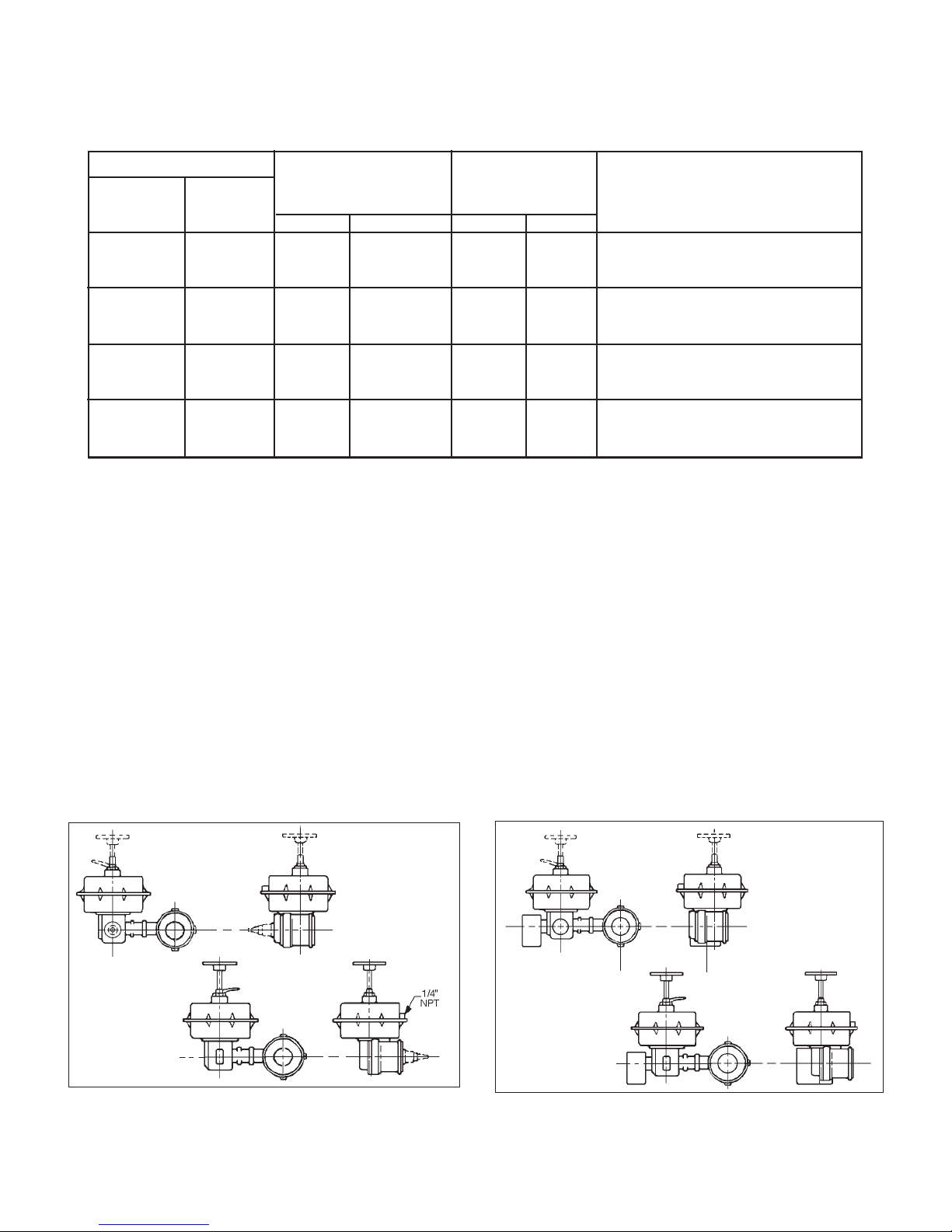
FIGURE 2: Mounting position of Ranger QCT to
Model 48 Actuator with Model 73N-B P/P Positioner.
2
FIGURE 3: Mounting position of Ranger QCT to
Model 48 Actuator w/Model 9540R or Smart Positioners.
IOM-48
Page 3
Position A
Position A
Position B
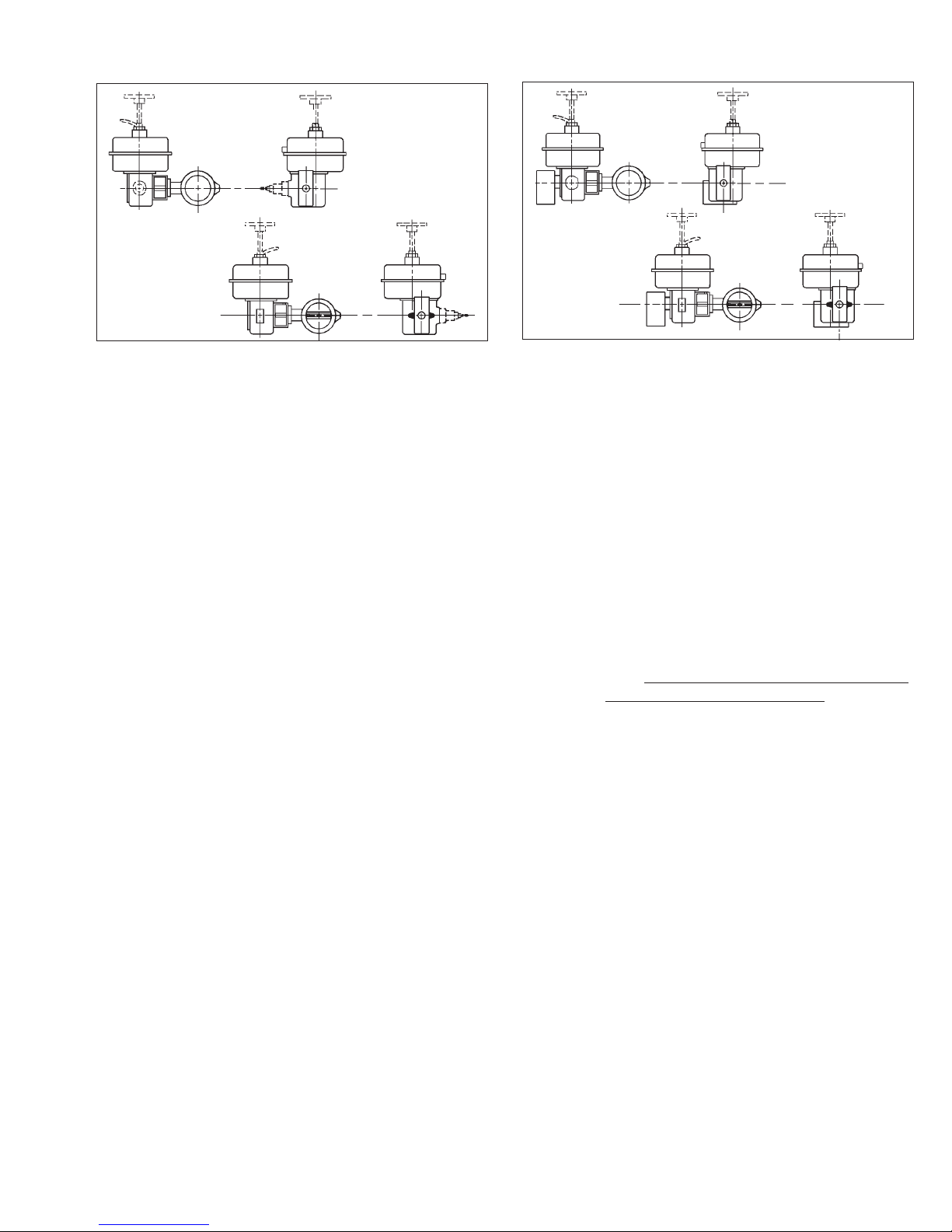
FIGURE 4: Mounting position of Premier EZO or Pre-
mier Unlined to Model 48 Actuator with Model 73N-B
P/P Positioner
3. A 1/4"–NPT female connection for pneumatic
LOAD is located on the side of the actuator’s
upper diaphragm casing near the casing
fl ange joint. Reference specifi c Ranger-TB or
Pre mier-TB for location of the connection.
4. Reference the valve body instructions — IOMRang er, IOM-Premier EZO or IOM-Premier
Unlined — for ad di tion al instructions on in stall ing unit in the process piping.
B. Air Supply:
1. Recommendation is that a desiccant dried,
instrument quality air supply be used. Such
a supply is recommended for outdoor in stal la tions, and is required in areas of freezing
weather conditions.
Position B
FIGURE 5: Mounting position of Premier EZO or Pre-
mier Unlined to Model 48 Actuator with Models 9540R
or Smart Positioners
2. If air supply contains moisture and/or lu bri cat ing oil, the air should be fi ltered with a co-
a lesc ing type of fi lter prior to use in stroking
the actuator.
3. Connection for the air loading pressure is 1/4"
female NPT. A suitable pipe thread sealant is
recommended to be used when installing the
pipe or tube fi tting. Exhibit care to prevent the
sealant from getting inside the tube/pipe.
4. If an alternate gaseous fl uid is used as a source
of loading pressure (i.e. natural gas, ni tro gen,
etc.), this gas MUST NOT BE COR RO SIVE
to the aluminum casing material.
IV. OPERATION
A. General:
1. Actuators supplied with 5-13 psig (0.34-0.90
Barg) benchset range are designed to op er ate
with or without a positioner. A 3-15 psig (0.21-
1.03 Barg) instrument output signal would be
required to operate without a positioner.
2. On larger valve body sizes the benchset
range is essentially 1.5–2.3 times that of the
5-13 psig (0.34-090 Barg); i.e. 7.5-19.5 psig
(0.52-1.34 Barg) or 10-26 psig (0.69-1.79
Barg) for Model 148’s. Either a signal booster
or a positioner will be required for full rotation
(0°–90°) by the actuator.
IOM-48
SECTION IV
3. If an “installed characteristic” other than the
“inherent characteristic” is desired, a positioner
plus a “char ac ter iza tion cam” is required. The
inherent characteristic of Rang er QCT control
valves is linear; for Premiers the inherent
characteristic is equal percent.
4. See Tables 2 through 4 for available actuator
models with benchset ranges per valve type
and body size. (Note: Model 148 actuators
included for clarity.) Proper MAX I MUM air
supply pressures are also indicated.
3
Page 4

TABLE 2
RANGER QCT
ACTUATOR BENCHSET RANGES
Valve Body Size
In. (DN)
1", 1-1/2" & 2"
(25, 40 & 50)
3" & 4"
(80 & 100)
4", 6" & 8"
(100,150, & 200)
Valve Body Size
In. (DN)
3" & 4"
(80 & 100)
6"
(150)
8"
(200)
10"
(250)
Actuator
Model
*
Failure
Action
48R-01 ATO-FC
48D-01 ATC-FO
148R-01 ATO-FC
148D-01 ATC-FO
148R-02 ATO-FC
148D-02 ATC-FO
PREMIER EZO
ACTUATOR BENCHSET RANGES
Actuator
Model
*
Failure
Action
48R-01 ATO-FC
48D-01 ATC-FO
148R-01 ATO-FC
148D-01 ATC-FO
148R-03 ATO-FC
148D-03 ATC-FO
148R-02 ATO-FC
148D-02 ATC-FO
Benchset
Range
psig (Barg)
5-15
(.34-1.03)
5-13
(.34-.90)
10-26
(.69-1.79)
TABLE 3
Benchset
Range
psig (Barg)
5-15
(.34-1.03)
5-13
(.34-.90)
7.5-19.5
(.52-1.34)
10-26
(.69-1.79)
Supply
Pressure
psig (Barg)
20
(1.4)
20
(1.4)
36
(2.5)
Supply
Pressure
psig (Barg)
20
(1.4)
20
(1.4)
27
(1.9)
30
(2.1)
Qty of Range
Springs
6
4
8
Qty of Range
Springs
6
4
6
8
TABLE 4
PREMIER UNLINED
ACTUATOR BENCHSET RANGES
Valve Body Size
In. (DN)
3" & 4"
(80 & 100)
6"
(150)
8" , 10"
(200, 250)
Actuator
Model
*
Failure
Action
48R-01 ATO-FC
48D-01 ATC-FO
148R-01 ATO-FC
148D-01 ATC-FO
148R-03 ATO-FC
148D-03 ATC-FO
Benchset
Range
psig (Barg)
5-15
(.34-1.03)
5-13
(.34-.90)
7.5-19.5
(.52-1.34)
Supply
Pressure
psig (Barg)
20
(1.4)
20
(1.4)
27
(1.9)
Qty of Range
Springs
6
4
6
* Model 148 included for clarity.
4
IOM-48
Page 5

SECTION V
V. MAINTENANCE
A. General:
1. Hereafter, all maintenance, disassembly, etc.,
is as sumed to be done in an indoor shop.
2. Most actuators are a sub-assembly that is
unitized with a body sub-assembly. Ref er ence
should be made to the IOM for the correct
body utilized.
3. Where the body is not being disassembled,
special care MUST be exhibited to prevent
valve stem rotation during any disassembly
or reassembly for all types of valves. Following this procedure will ensure not damaging
seat ing surfaces.
4. Remove all instrument tubing and in ter con nect ed electrical wiring. Label “ends” to en sure
proper reconnection.
5. All indicated Item Numbers that are with re spect to IOM-Ranger, IOM-Premier EZO or
IOM-Premier Unlined will be in parenthesis
and underscored; i.e. (20); the same is true
for Model 73N-B P/P positioner parts.
6. All Item Numbers that are with respect to this
IOM-48 are not underscored; i.e. (19).
7. Item Numbers that relate to the Model 9540
or Smart positioners ((PA)) are in a double
set of pa ren the sis and are underscored; i.e.
((3)).
B. Separation of Body Assembly (BA) from Ac-
tu a tor Assembly (AA):
1. Place completely joined valve assembly (AA)
(BA) upon a fl at work surface with suf fi cient
room to move the individual sub-as sem blies
(AA) (BA) around. Place matchmarks on valve
yoke (12), arm housing (4) and ac tu a tor lower
casing (2) to use as ref er enc es.
2. Remove cover plate (20) away from arm
hous ing (4) by removing four machine screws
(36).
washer (55) se cur ing the bright or angecol ored travel in di ca tor (16) to the upper
end of valve stem (Rang er (7)), (Premier
(3.2)) using a 7/32" allen key wrench. Re move travel in di ca tor (16) off of pro trud ing
lo ca tor pin (51).
c. If equipped with a Model 73N-B P/P po-
sitioner, re move the four cap screws (33)
that secure the positioner assembly (PA)
to the arm housing (4) using a 3/16" allen
key wrench. Remove positioner as sem bly
(PA) and feed back range spring (102).
Loop a 6" piece of fi ne wire around the
feedback linkage subassembly (72). Place
one screw (33) back into a tapped open ing.
Pull wire taut and wrap around pro trud ing
screw (33) to keep the linkage (72) from
interfering with further dis as sem bly.
3B. Units with End-of-Shaft Model 9540R Posi-
tioners:
a. Remove clear indicator cover ((22)) by
removing two cap screws ((A3)).
b. Remove red plastic pointer ((34)) by pull-
ing outwards from hub of post-end screw
((23)).
c. Make a matchmark on the char ac ter iza-
tion cam ((24)) at the point where the cam
follower ((31)) touches. Using a wrench
remove post-end screw ((23)) that se cures
characterization cam ((24)). Pull feedback
lever ((13)) downwards; re move cam
((24)) and adhered to lock toothed washer
((28)) and shouldered wash er ((27)).
d. Remove the positioner unit ((I/P)) ((P/P))
from the baseplate ((26)) by removing cap
screws ((11)) with lock washers ((12)) from
side and back of baseplate ((26)).
e. Remove the four cap screws ((78)) se cur-
ing the bracket ((76)), baseplate ((26))
assembly and coverplate (13) to the arm
housing (4).
3C. Units with End-of-Shaft Model 991 or PS2 I/P
Positioners:
3A. Units with Model 73N-B P/P Positioner or No
Positioner, and No Travel Limit Switch:
a. Using a 3/16" allen key wrench, remove
the three cap screws (31) securing the
dial lens (14), travel indicator dial (15)
and coverplate (13).
b. Remove cap screw (32) and lock tooth
IOM-48
a. Remove cap screws (31) securing the
positioner mounting bracket ((9)) to coverplate
(13).
b. Set positioner/bracket assembly to the
side.
c. Remove set screw ((16)), washer ((17))
from end of valve stem (Ranger (7)), (Premier
(3.2)) securing carrier linkage ((3)) to stem.
d. Remove linkage ((3)) from end of stem.
5
Page 6

4. For ATO-FC valve action, it is necessary to
remove the “stem windup”.
a. Rotate manual handwheel operator
(MHWO) handwheel (58.1) ap prox i mate ly
1-3 revolutions CW (viewed from above
handwheel) until interconnecting arm and
stem linkage (5, 10) of actuator “relax”.
b. Pressurize actuator casing (1) only
until the in ter con nect ing arm and stem
linkage (5,10) “relax”. DO NOT OVERPRES SUR IZE.
body assembly (BA) from Figures 6-9, fol low ing pages.
2. The valve body/bonnet (1) to valve body
yoke (12) can be rotated in four 90° increments around the centerline of the valve shaft
(Rang er (7)) (Premier (3.2)).
3. Separate the actuator assembly (AA) from
the body assembly (BA) as described in this
Sec tion, V.B.1. through V.B.9.
NOTE: Do not remove the drive coupling ((32))
unless required.
5. Remove ball bearing (18), both bearing fl ang es
(19) and indicator spacer (17) over shaft-end
(Ranger (7)), (Premier (3.2)).
6. For actuator with a handwheel (58), rotate
handwheel CW (viewed from above), driving the arms (5) down until the shoulder bolt
(40) clears the ears on the arm housing (4). If
actuator does not include a handwheel (58),
loosen jam nut (44) and, using a 9/16" open
end wrench, rotate the hex portion of the push
rod (10) until the shoulder bolt (40) clears the
ears on the arm housing (4).
7. Remove lock nut (46) that secures shoulder
bolt pin (40) through lever arms (5). Remove
shoulder bolt pin (40).
8. Grasp lever arms and rotate stem (Ranger
(7)), (Pre mier (3.2)) as required to pull down
and away from the lower rod end-L.H. (9) to
allow clearance to remove arms (5). Slide
subassembly consisting of both arms (5),
spacer (12) or characterization cam (Model
73N-B (12)), and two spring pins (50) out wards
and away from the arm housing (4) and over
shaft-end (Ranger (7)), (Premier (3.2)).
9. While securely holding the actuator assembly
(AA) with an overhead sling support, and the
body assembly (BA) to prevent movement,
remove the four bolts (24) that secure the
body yoke (12) to the actuator arm housing
(4). Slide the actuator assembly (AA) over the
stem-end (Ranger (7)), (Pre mier (3.2)). Lay
body assembly (BA) aside.
C. Changing Actuator Mounting Position (With
No Change in Failsafe Action).
4. Determine if it is necessary to interchange
packing studs (21) on Ranger or Premier
Un lined, and yoke (12) attachment hex head
cap screws (19) on Rang er or Premier Un lined
per fol low ing:
Degrees Packing Studs
Rotary Valve Rotation Yoke Attach Studs
Position Change Switch of Position
Ranger, 90°, 270° Required
Premier Unlined 180° Not Required
Premier EZO 90°, 180°, 270° Not Required
5. If required, remove both packing fl ange stud
nuts (22) on Ranger or Premier Unlined, and
any external live-loaded packing com po nents
(Rang er (27) (28) (29)), and set both aside
carefully to prevent an “inadvertent mix ing”
of the component’s “stack-up”.
6. Place matchmarks between yoke (12) and
valve bon net/body (1). While holding yoke
(12) with hand, remove two cap screws (19)
and pull yoke (12) over end of stem (Ranger
(7)) (Premier (3.2)) and set aside.
7. If necessary, remove studs (21) from Ranger
or Premier Unlined body assembly (BA) and
re lo cate/in ter change as re quired.
8. Reposition yoke (12) back onto body bonnet
(1), shifted/rotated the number of degrees
re quired (i.e. 90°, 180° or 270°), using the
matchmarks to guide to correct position. Se cure yoke (12) to body bonnet (1) by engaging
two cap screws (19). Torque per following:
1" & 2" Rangers — 35-40 ft-lbs (47-54
N-m)
3" & 4" Premiers, lined & unlined —
75-80 ft-lbs (101-108 N-m).
1. Determine the desired mounting position of
actuator assembly (AA) with respect to valve
6
IOM-48
Page 7
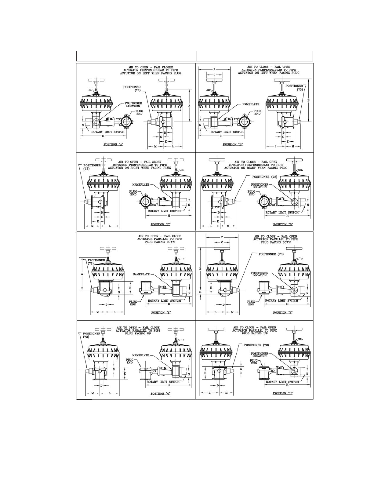
FIGURE 6:
ORIENTATION – RANGER QCT ACTUATOR MOUNTING POSITIONS
WITH MODEL 73 P/P POSITIONER
REVERSE ACTION DIRECT ACTION
NOTES: 1. Flangeless valve design indicated; integral fl anged units follow same orientation.
2. Dimension tables are included in the Ranger-TB.
IOM-48
7
Page 8
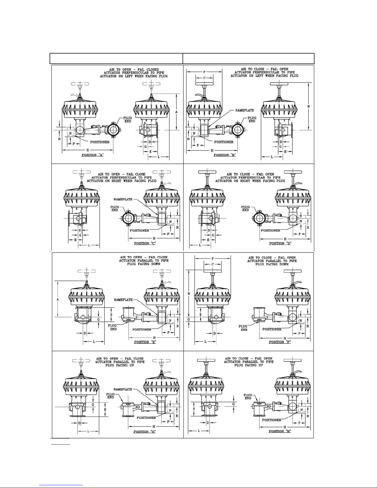
FIGURE 7:
ORIENTATION – RANGER QCT ACTUATOR MOUNTING POSITIONS
WITH MODELS 9540R P/P or 991 or PS2 I/P POSITIONERS
REVERSE ACTION DIRECT ACTION
NOTES: 1. Flangeless valve design indicated; integral fl anged units follow same orientation.
2. Dimension tables are printed in the Ranger-TB.
8
IOM-48
Page 9
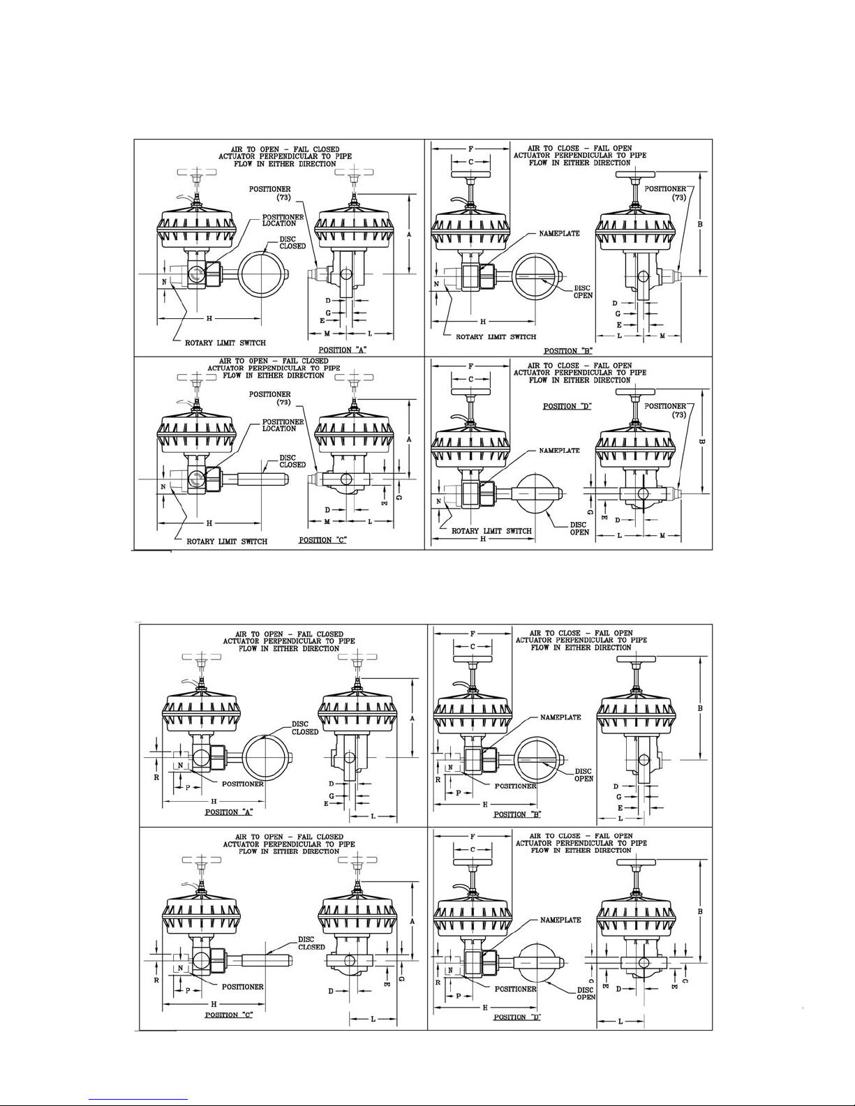
FIGURE 8
PREMIER ACTUATOR MOUNTING POSITIONS – 73
Position "A" is standard for fail closed action. Position "B" is stan dard for fail open action.
Po si tion "C" and "D" covers ver ti cal piping.
FIGURE 9
PREMIER ACTUATOR MOUNTING POSITIONS – 9540R/991/PS2
Position "A" is standard for fail closed action. Position "B" is stan dard for fail open action.
Po si tion "C" and "D" covers ver ti cal piping.
Note: All basic valve dimensions are printed in the Premier-TB
IOM-48
9
Page 10

9. Reposition packing fl ange (Ranger (14))
(Pre mier Unlined (5)) over packing studs (21)
for Ranger and Premier Unlined. Reinstall
live-loaded packing components (Rang er (27)
(28) (29) 2 sets). Reengage both pack ing stud
nuts (22) for Ranger and Premier Un lined. Set
torque level on pack ing stud nuts as indicated
in IOM-Ranger QCT, IOM-Pre mier EZO, or
IOM-Premier Unlined body as sem bly (BA)
instructions.
10. Reorient body assembly (BA) with respect to
the actuator assembly (AA). Rejoin the body
assembly (BA) to the actuator assembly (AA)
as described in this section, V.I. Ensure prop er
plug (Ranger (6)) or disc (Premier (3.1)) po si tion prior to reinstalling lever arms (5). Ensure
that the lever arms (5) are “centered” within
the arm housing (4), and with respect to the
actuator stem linkage (8) (9) (10) (43) (44).
11. Recalibrate the unit (AA) (BA) and its positioner
((PA)).
D. Changing Failsafe Action:
3. To reverse actuator (AA) failsafe action ba si cal ly requires:
a. Moving lever arms (5) from left side of
valve’s stem (Ranger (7)) (Premier (3.2))
to right side, or vice versa. This is ac com plished by removing actuator assembly
(AA) from body assembly (BA) and ro tat ing
actuator (AA) 180° about the ac tu a tor’s
stem linkage (8) (9) (10) (43) (44). See
Figure 10 and Figure 11.
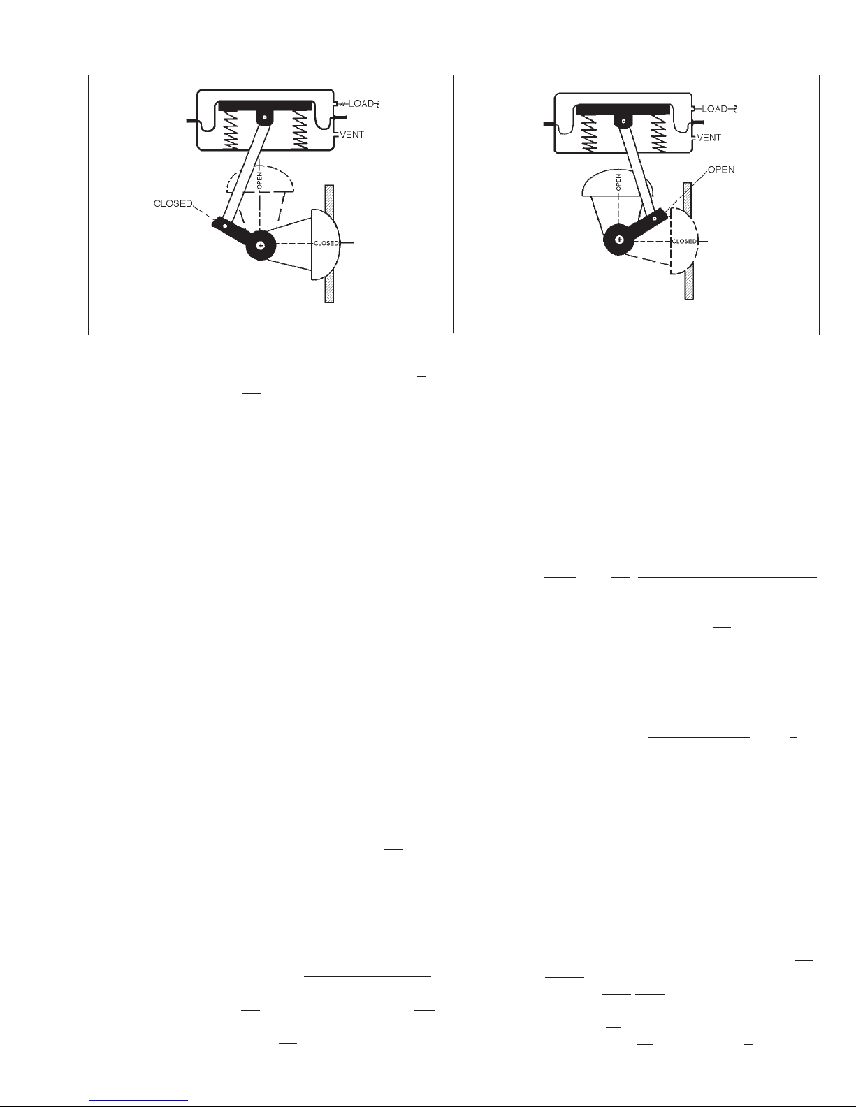
b. Rotating plug (Ranger (6)) or disc (Pre mier
(3.1)) by 90°; ie. from “closed” po si tion to
“open” position, or vice versa.
c. Reconnecting actuator (AA) to body (BA)
with lever arms (5) also rotated 180°.
NOTE: Valve stem always goes CW to “close”,
viewed from stem-end.
4. Separate the actuator assembly (AA) from
the body assembly (BA) as described in this
Sec tion, V.B.1. through V.B.9.
5. Rotate plug (Ranger (6)) or disc (Premier (3.1))
position 90° to new failsafe position.
1. The Model 48 actuator (AA) is fi eld-re vers ible
for failsafe action with no additional parts
required.
2. It is possible that both of the following can
occur together for the degree of disassembly
undertaken:
a. Failsafe action reversed.
b. Change in actuator mounting position.
NOTE: This section will be limited to the pro ce dures
for 2.a. above. If 2.b. is also desired, then it will be
necessary to reference Sub sec tion C. here in for
the added procedural steps as required.
This subsection will thus be limited as in di cat ed as
follows (reference Figures 6 – 9 herein for be gin ning and end graphic orientations).
Product Begin End
Position Action Position Action
“A” ATO-FC “B“ ATC-FO
“C” ATO-FC “D” ATC-FO
“E” ATO-FC “F” ATC-FO
Ranger QCT “G” ATO-FC “H” ATC-FO
“B” ATC-FO “A” ATO-FC
“D” ATC-FO “C” ATO-FC
“F” ATC-FO “E” ATO-FC
“H” ATC-FO “G” ATO-FC
Premier EZO “A” ATO-FC “B” ATC-FO
or “C” ATO-FC “D” ATC-FO
Premier “B” ATC-FO “A” ATO-FC
Unlined “D” ATC-FO “C” ATO-FC
10
6. Slide actuator assembly (AA) that has been
rotated 180° back over the stem-end (Ranger
(7)) (Premier (3.2)). Align bolt holes between
arm housing (4) and valve yoke (12).
7. Reengage bolting (24) securing arm housing
(4) to yoke (12). Torque bolting (24) to 17-20
ft-lbs (23-27 N-m).
8. Ensure that the reinstalled lever arms (5) are
also rotated 180° in the same reference as the
actuator as sem bly (AA) was rotated. (NOTE:
The repositioned arms (5) will appear to have
only changed relative position by 90° in an oth er
plane.) Ensure the lever arms assembly (5)
is “centered” within the arm housing (4), and
with respect to the actuator stem (8) (9) (10)
(43) (44).
9. Rejoin the body assembly (BA) to the actuator
as sem bly (AA) as described in this Section,
V.I.
E. Diaphragm Replacement:
1. Place unit assembly (AA) (BA) onto a fl at work
bench with actuator upper casing (1) on top
side; i.e. handwheel (58), if supplied, on top
side.
2. Ensure that all air pressure is released from
actuator assembly (AA) casing (1).
IOM-48
Page 11
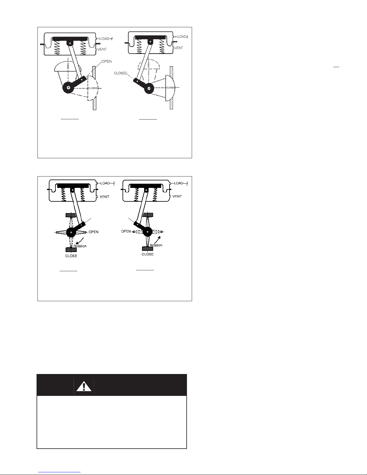
CCW-TO-OPEN
ATC-FO
(DIRECT)
Push Down-to-Close
NOTE: To switch “action” requires locating actuator stem
to opposite side of valve stem.
CCW-TO-OPEN
ATO-FC
(REVERSE)
Push Down-to-Open
5. Loosen all casing (1,2) fl ange bolting (27, 28,
41, 42) two revolutions. Pry apart the casings
(1,2) if “stuck” together.
6. In one revolution increments loosen all op-
pos ing nuts (41, 42) until the short bolting
(27, 41) disengages and can be removed.
Con tin ue loosening extension nuts (42) in
the alternating, one revolution pattern ensuring that the cas ings (1, 2) are being “pushed
apart”, until the extension bolting (28, 42) is
disengaged and removed.
7. Lift the upper casing (1) upwards and away
from the lower casing (2). Set upper casing
(1) aside.
Figure 10
Ranger Plug vs. Lever Arm vs. Actuator Ori en ta tion
CCW-TO-OPEN
ATC-FO
(DIRECT)
Push Down-to-Close
NOTE: To switch “action” requires locating actuator stem
to opposite side of valve stem.
CCW-TO-OPEN
ATO-FC
(REVERSE)
Push Down-to-Open
Figure 11
Premier Plug vs. Lever Arm vs. Actuator Ori en ta tion
3. Ensure that manual handwheel (58) operator
is fully rotated upwards by loosening locking
lever (59) and ro tat ing CCW (viewed from top
side) as far as possible.
4. Place a matchmark between actuator casings
(1) (2).
WARNING
SPRING UNDER COMPRESSION. Prior to re mov ing
fl ange bolting (27, 28, 41, 42) re lieve range spring
(11) compression by rotating the handwheel or
adjusting screw assembly (58) CCW (viewed from
above handwheel (58) until all spring com pres sion
is re lieved. Fail ure to do so may result in fl ying
parts that could cause personal injury.
8. Remove pivot screw (25) by rotating CCW
(viewed from above), and seal (56).
9. Pry diaphragm washer (52) loose. Clean
wash er (52) of any rubberized sealant.
10. Prior to diaphragm (6) removal, inspect to see
where a diaphragm (6) leak may have been
caused by wearing against the upper case (1)
at any point. Inspect the upper case (1). NOTE:
The diaphragm (6) is a rolling di a phragm and
should NOT touch the upper case (1) at any
point of the piston’s (3) up wards/downwards
travel. If there is side move ment of the piston
(3), further dis as sem bly for inspection of range
springs (11) is man da to ry. If there is topside
wear, uptravel stop washer (54) is not prop er ly
adjusted.
11. Remove diaphragm (6) and discard.
12. Clean surface of piston (3) of any foreign
material that could cause a premature failure
of diaphragm (6) if cov ered. Turn diaphragm
(6) “inside-out”. Place diaphragm (6) onto
piston (3) centered over the center bolt hole
in piston (3); ensure that the smooth black
sur face of di a phragm (6) is on the “pressurized air-side”.
13. Place silicone sealant, Dow-Corning “Silastic”
#732 RTV or equal, around the diaphragm’s
(6) center bolt hole opening. Lay diaphragm
washer (52) onto sealant and centered over
bolt hole. Replace seal (56) on top of washer
(52).
14. Place a tool around the skirt circumference
of the piston (3) to secure during tightening;
use tape or similar material to prevent this tool
from leaving sharp edges that could damage
IOM-48
11
Page 12

the new diaphragm (6). Place Locktite #242,
or equal, thread sealant onto the threads of
pivot screw (25); engage and tighten screw
(25) to 15-20 ft-lbs (21-27 N-m) torque. NOTE:
Piston (3) must be held from rotating to pre vent
the multiple nested range springs (11) from
tilting away from a common vertical centerline
be tween hubs of lower case (2), piston (3) and
range spring (11).
15. Fold the diaphragm (6) skirt from its insideout ori en ta tion, down and around the piston’s
(3) skirt. Using a rounded-end tool, push the
diaphragm (6) down between the lower cas ing
(2) sidewall and the piston’s (3) skirt, forming
a “valley”. Work diaphragm (6) to ensure that
all folds or “puckers” are taken away. Press
the di a phragm’s (6) lower/outer beaded edge
into the groove. Again, smooth out all folds or
puckers in diaphragm (6).
16. Place a light coating of graphite powder
lu bri cant, (dry mo lyb de num disulfi de) on the
skirt ed areas of diaphragm (6), and into the
“valley”. This lubricant will prevent the di a phragm (6) from “sticking together” or abrad ing
itself dur ing piston (3) travel.
17. If actuator (AA) is supplied with a manual handwheel operator (MHWO), place a heavy-duty
wheel bearing grease, Lubriplate No. 130-AA,
or equal, into the v-notch in the head of the
pivot screw (25).
WARNING
1. Elongated extension bolting (28) (42) is a safe ty
feature to allow relaxation of range springs (11)
to the piston’s (3) mechanical uptravel stop at
dis as sem bly.
2. Extension bolting (28) (42) should ONLY be
re placed with factory replacements; do NOT
sub sti tute con ven tion al bolting.
3. Extension bolting (28) (42) MUST be located
180° opposite of each other in the fl ange bolt-
ing array. Failure to heed could cause per son al
injury at a later dis as sem bly.
21. Place the same friction-reducing thread lu bri cant into the threaded portion of both ex ten sion
nuts (42). NOTE: Only one end of ex ten sion
nut (42) is threaded. It is not possible to engage the extension bolting (28) (42) with the
extension nut (42) upside down; the threads
of the nut (42) will not engage.) Engage both
extension nuts (42) until they draw tight to the
lower casing (2) fl ange’s underneath side.
Place one short bolt (27) through a bolt hole
of upper fl ange (1) to serve as an indicator. In
one-rev o lu tion increments and an al ter nat ing
cross-pattern, draw the casing (1) (2) fl anges
to wards each other. When there is at least
one-half of the indicator short bolt (27) threads
exposed through the lower casing (2) fl
engage nut (41) until the short bolting (27)
(41) is fi nger-tight.
ange,
12
18. Inspect working of manual handwheel op er a tor (MHWO) located within the upper casing
(1) for signs of wear. Go to Subsection F. for
maintenance of manual handwheel operator
(MHWO).
19. Place properly oriented upper casing (1) down
onto the lower casing (2) with matchmarks
aligned and all casing fl ange bolt holes cen-
tered. NOTE: The casing fl anges (1) (2) will
not touch together.
20. Insert both extension bolts (28) through two
upper casing (1) bolt holes that are located
180° across from each other; these bolts
should extend through the lower casing (2)
fl ange enough to engage its companion ex ten sion nut (42). Place a friction-reducing thread
lubricant on the lower exposed threads of the
extension bolts (28).
22. Place all short bolts (27) through the re main ing
upper casing (1) fl ange bolt holes, and engage
each ones nut (41) until the short bolting (27)
(41) is fi nger-tight.
23. In an alternating cross-pattern, tighten all
fl ange bolt ing (27) (28) (41) (42) in onerev o lu tion increments. When all bolting (27)
(28) (41) (42) is hand-wrench tight, torque to
levels indicated below:
Item Torque Req’d
Nos. Description ft-lbs N-m
27, 41 Short Bolting 15–18 20–24
28, 42 Extension Bolting 8–12 11–16
24. Connect a temporary instrument air source
di rect ly to the 1/4" FPT connection in the upper casing (1). Pres sur ize to the “Air Supply
Pressure” level as indicated in Table 2-4 of
IOM-48
Page 13

Section IV.A.4. for the corresponding actual
benchset range of the actuator being ser viced,
and test for leakage at upper casing (1) to
lower casing (2) joint. Also test for leakage at
man u al handwheel operator (MHWO), ro tat ing handwheel (58) in and out several times
dur ing the test.
25. Release all air pressure into actuator upper
casing (1); remove air source from 1/4" FPT
connection.
F. Manual Handwheel Operator:
1. Reference Item Number drawing at end of IOM
for de tails of the man u al handwheel op er a tor
(MHWO) sub-assembly.
2. Place unit (AA) (BA) on a fl at work surface
with the handwheel (58) on topside.
wheel (58.1) end) back into the handwheel
gland (67). When stem (58.2) protrudes far
enough through gland (67), re lo cate locking
pliers to opposite end and ro tate stem (58.2)
until stem (58.2) fully dis en gag es.
12. Remove O-ring (62) from handwheel gland
(67).
13. Remove O-ring (63) from handwheel stem
(58.2).
14. Place parts (58.2) (59) (60) (64) (67) into a
suitable solvent and clean as much as pos si ble, remove parts and allow to dry.
15. Inspect handwheel stem (58.2) with em bed ded
ball (64) for wear on ball (64). If ball (64) is
worn, or threads of stem (58.2) are dam aged,
replace handwheel sub-assembly (58); i.e.
parts (58.1) (58.2) and (64).
3. Ensure all air pressure has been released from
ac tu a tor casing (1). Ensure handwheel (58)
is fully “backed-out” by rotating CCW (viewed
from above); i.e. is as “high” as pos si ble.
4. Remove slotted-head screw (65) securing
handwheel gland (67) to upper casing (1).
5. Place a smooth-jawed wrench onto handwheel
gland (67) and rotate CCW (viewed from
above) to removal of the manual handwheel
operator sub-assembly (MHWO).
6. Place the sub-assembly (MHWO) into a vise,
grasping with leaded jaws on the coarsescrewed handwheel stem (58.2) near the
base of the handwheel (58.1), oriented to
allow driving-out the rolled pin (66) securing
the handwheel (58.1) to the handwheel stem
(58.2).
7. Drive pin (66) out using a suitable punch and
locking pliers. Set pin (66) aside for reuse. Remove handwheel (58.1) from stem (58.2).
8. Rotate locking lever (59) CCW (viewed from
handwheel-end) to removal.
9. Slide washer (60) and threadseal washer
(61) off handwheel stem-end (58.2). Discard
threadseal washer (61).
16. If handwheel gland (67) shows signs of wear
in female threads (i.e. loose gauging), replace
handwheel gland (67) and self-tapping slot ted-head screw (65). NOTE: A re place ment
handwheel gland (67) will require drilling a
new 5/32" x 1-1/16" (4mm x 25.5mm) deep
hole into the lip of the upper casing (1).
17. Install new O-ring (63) onto handwheel stem
(58.2).
18. Install new O-ring (62) onto handwheel gland
(67).
19. Place a thin coat of lithium grease on the
handwheel stem O-ring (63) and the im me di ate surrounding area of the handwheel stem
(58.2).
20. Engage the handwheel stem (58.2) into the
gland’s (67) underneath side. When the handwheel (58.1) end of the stem (58.2) pro trudes
through the gland’s (67) upper side, place a
new threadseal washer (61) over the stem’s
(58.2) upper end. Continue engaging stem
(58.2) until the O-ring (63) is pulled into the
gland (67).
21. Install washer (60) and locking lever (59) onto
stem (58.2).
10. Remove remaining engaged parts (67) (58.2)
from vise. Reorient horizontally in vise along
fl ats of handwheel gland (67).
11. Place stick punch in drive-pin hole and rotate
handwheel stem (58.2) CW (viewed from hand-
IOM-48
22. Place handwheel stem (58.2) into a soft-jawed
vise. Position handwheel (58.1) onto stem
(58.2) with holes for pin (66) aligned. Insert
pin (66) and drive through stem (58.2) and
handwheel (58.1) far side. Remove handwheel
assembly (MHWO) from vise.
13
Page 14

23. Place heavy duty wheel bearing grease as
specifi ed previously onto the stem-end ball
(64). Engage the gland (67) into the upper
casing (1) female opening. Align tapped open ing for self-tapping slotted-head screw (65).
24. Install slotted-head screw (65) fully.
G. Adjusting Screw Assembly and Actuator Plug
Maintenance:
1. Reference Item Number drawing at end of the
IOM.
WARNING
Do NOT stick hand or fi ngers into the arm housing (4)
when the actuator is pressurized. ONLY USE TOOLS
WITHIN ARM HOUSING (4).
4. Place a wrench on the hex surface of the ac tu a tor’s stem/pushrod (10). Rotate the push
rod (10) CCW (viewed from lower L.H. rod
end (9)); keep track of number of revolutions
to disengage from upper R.H. rod end (8) in
box below.
2. Determine the portion of the text of Sub sec tion F. above that would apply to the adjusting screw assembly (ASA) counterpart of the
manual handwheel operator (MHWO) as sem bly, and complete maintenance in a sim i lar
procedure. NOTE: Adjusting screw assembly
(ASA) is ONLY applied to reverse-action,
ATO-FC Ranger QCT units (AA) (BA).
3. Determine the portions of the text of Sub sec tion
F. previous that would apply to the ac tu a tor
plug (67) coun ter part of the manual handwheel
operator (MHWO) as sem bly, and complete
maintenance in a similar procedure. NOTE:
Actuator plug (67) may be applied on all Premier units (AA) (BA) and ONLY direct-action,
ATC-FO Ranger QCT units (AA) (BA).
H. Replacement of Range Springs:
1. Replacement of actuator assembly (AA)
range springs (11) requires what is essentially a complete actuator (AA) disassembly.
It is rec om mend ed that the range spring (11)
re place ment should include:
a. diaphragm (6) replacement
b. O-ring(s) (62) (63) replacement
c. threadseal (61) replacement.
2. Separate the actuator assembly (AA) from
the body assembly (BA) as described in this
Sec tion, V.B.1 through V.B.9.
3. Push piston (3) downwards by:
a. manual handwheel operator (MHWO)
being rotated CW (viewed from above
handwheel (58.1)) approximately one-half
of full travel.
b. pressurize actuator to approximately one-
half of the stated benchset range; i.e. for
5-15 psig (.34-1.03 Barg) pressurize to
ap prox i mate ly 10 psig (.69 Barg).
Number of revolutions of push
rod (10) re quired to disengage
from upper R.H. rod end (8). ___________
5. Allow piston (3) to travel upwards by:
a. manual handwheel operator (MHWO)
being rotated CCW (viewed from above
handwheel (58.1)) fully out/up.
b. releasing air pressure as applied per 3.b.
above; remove the air supply from ac tu a tor
upper casing (1).
6. Orient actuator assembly (AA) with upper casing (1) on top side. Disassemble the ac tu a tor
assembly (AA) to the point of di a phragm (6)
replacement as described in this Section V.E.1
through V.E.11.
7. Place a matchmark at fl ange of lower casing
(2) and correspondingly at piston (3). Lift off
piston (3) in a vertical direction to prevent
tipping range springs (11) over. Set piston
(3) on work surface upside down.
8. Remove all range springs (11) and set in a row
side-by-side. Inspect for any difference in the
spring (11) height or verticality. Replace any
abnormal spring(s) (11). Re place any springs
(11) that show cracks, nicks, damaged epoxy
coating, corrosion, etc. Inspect springs (11)
using data in table below as the “normal”:
Benchset Free
Part Range Qty. of Height * Coating
Number psig (Barg) Springs in (cm) Color
830-H2-5-R9069-95 5-15 6 5.60 Grey
(0.34-1.03) (14.23)
* Acceptable ± 1/8" (± 3 mm)
14
IOM-48
Page 15
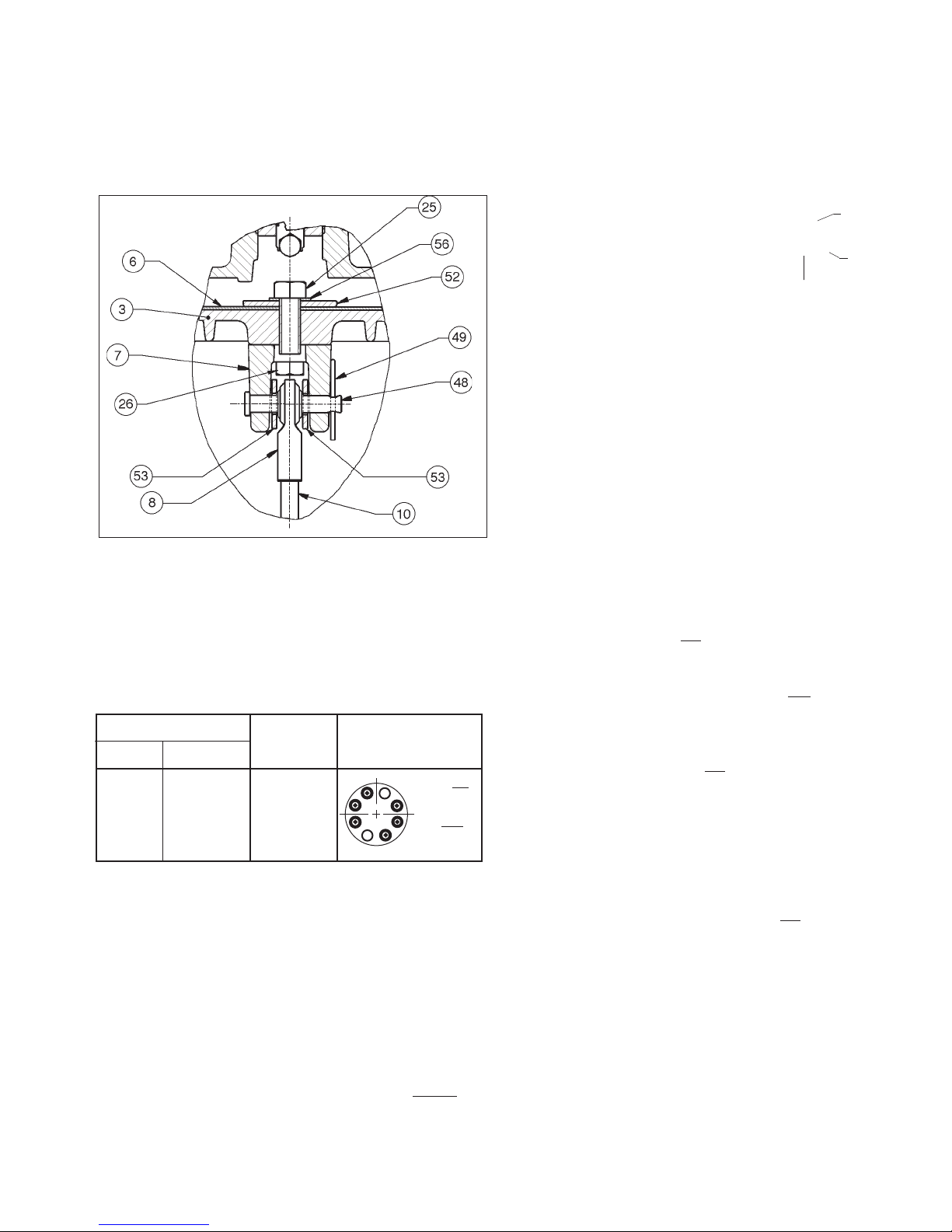
9. Inspect clevis (7), upper R.H. rod end (8), clevis
pin (48), washers (53) and hairpin (49) for signs
of looseness and/or wear; re place any worn
parts. Check bolting (26) for loose ness; tighten
as necessary to 15-18 ft-lbs (20-23 N-m).
12. Reinstall a new diaphragm (6) and re as sem ble
the upper casing (1) as described in this Section, V.E.12 through V.E.24.
13. Using air pressure of V.E.24., pressurize
the actuator upper casing (1) to the upper
value of the stated benchset range plus 2 psi
(0.14 Bar); i.e. for 5-15 psig (0.34-1.03 Barg)
benchset range, pressurize to 15+2 = 17 psig
(1.03+0.14 = 1.17 Barg). This pressure level
should cause the piston’s (3) lower skirt-edge
to bottom out on the lower casing (2).
14. Using only tools (i.e. no fi ngers within arm
housing (4)) to grasp the actuator stem/push
rod (10), insert push rod (10) with in ter con nect ed parts (9) (43) (43) (44) (54) into arm
housing (4) and engage into dangling upper
R.H. rod end (8) by rotating CW (viewed from
lower L.H. rod end (9)). Count number of
revolutions of push rod (10) en gage ment to
match those recorded in Article 4., previous,
at removal.
Figure 12
Piston & Clevis Close-up
10. Place range springs (11) back onto hubs of
lower casing (2) per following table:
NOTE: Every spring (11) has another spring (11) 180°
across/opposite.
Benchset Range Quantity
psig (Barg) of Springs Array
Hub w/NO
Spring (11)
5-15 (0.34-1.03) 6
Hub With
Spring
(11)
11. Aligning matchmarks of Article 7. above,
re po si tion piston (3) back onto top side of
range spring (11) array. Using a mirror tool
and fl ashlight, look through the rect an gu lar
open ing in the lower casing (2) from within the
arm housing (4) to ensure that the piston (3)
hubs are centered within the ID of the range
spring (11) coil. It may be necessary to use
a tool to move the upper end of the range
spring (11) as necessary to be “captured” by
a piston (3) hub. Each spring (11) MUST be
captured by a hub on top and bottom ends.
15. Release all air pressure into actuator upper
casing (1); remove air source from 1/4" FPT
connection.
16. Join the actuator assembly (AA) to the body
assembly (BA) as described in this Section,
V.I.
I. Joining of Body Assembly (BA) to Actuator
As sem bly (AA):
1. Determine proper orientation of actuator
(AA)-to-body (BA) for the following considerations:
• failsafe action
• installed piping orientation.
Reference Sub-sections V.C. and V.D. to see
sche mat ics of orientations available.
2. Position body assembly (BA) on a fl at work
surface. Orient such that the actuator as sem bly (AA) can be ori ent ed with the top of
the actuator upper casing (1) on topside; i.e.
man u al handwheel operator sub-assembly
(MHWO) stem (58.2) vertically oriented, if
supplied.
3. Using an overhead hoist, lift the actuator
as sem bly (AA) (with position indicator ap pa ra tus (13,14,15,16,17,31,31,34), lever arm
ap pa ra tus (5,5,12,40,46,50,50), end-of-shaft
IOM-48
15
Page 16

bearing (18), bearing fl anges (19) and cover
plate (20) removed) prop er ly ori ent ed and shift
lat er al ly over the pro trud ing stem (Rang er (7),
Premier (3.2)). Bring the round opening of
the arm housing (4) into position against the
mounting yoke (12). Raise/lower/tip/rotate the
actuator assembly (AA) to align at least one
bolt hole of the yoke (12) with one bolt hole
in the arm housing (4). Insert one cap screw
(24) from behind the yoke's (12) bolt hole and
engage with the tapped opening in the arm
housing (4); fi nger tighten cap screw (24).
4. Reposition actuator assembly (AA) as re quired
to align the remaining bolt holes se cur ing
yoke (12) with arm housing (4). In sert the cap
screws (24) and fi nger-tighten.
5. (Wrench-tighten in one-half revolution in cre ments and in an alternating cross-pattern
the three cap screws (24) securing actuator
as sem bly (AA) to body assembly (BA). Final
tightening should be by torque wrench to 1720 ft-lbs (23-27 N-m)
6A. For units (AA, BA) with Model 73N-B P/P
positioner:
a. Secure characterization cam (12) prop er ly
oriented over the two rolled spring pins
(50) stuck into the inner lever arm (5).
b. Place the outer lever arm (5) over the
two spring pins (50) with the bolt holes
align ing. Press the apparatus (5,50,50,5)
to geth er.
into place. Center-align lever arm apparatus
(5,50,12,50,5) transversely within the arm
housing (4), directly over stop screw (35).
9A. For units (AA, BA) with Model 73N-B P/P po-
sitioner: Place indicator spacer (17) over end
of shaft (Ranger (7), Premier (3.2)) prop er ly
oriented for travel indicator (16) to be “located”
by spring pin (51).
9B. For units (AA, BA) with Model 9540R P/P
positioner or 991 or PS2 I/P positioner: Reference the IOM-9540R or 991/PS2 IOM for
proper instructions on reinstallation of in di ca tor
spacer (17) and drive coupling ((32)).
10. Align the bolt holes in lever arms (5) and lower
L.H. rod end (9). NOTE: For units (AA, BA)
with ATO-FC action it will be necessary to
offset “stem windup” by –
a. Rotating manual handwheel operator
(MHWO) handwheel (58.1) ap prox i mate ly
1-3 rev o lu tions CW (viewed from above
handwheel) until the bolt holes of lever
arms (5) and lower L.H. rod end (9) are
aligned.
b. Pressurize actuator casing (1) only until
the bolt holes of the lever arms (5) and
the lower L.H. rod end (9) align.
11. Insert shoulder bolt (40) through the round
opening of the arm housing (4) and into the
bolt holes of lever arms (5) and lower L.H. rod
end (9).
16
6B. For Units (AA, BA) with no positioner, Model
9540R P/P positioner or 991 or PS2 I/P:
a. Similar to 6A. above, except a spacer
wash er (12) replaces the cam (12) of a
Model 73N-B P/P positioner.
7. Position valve plug (Ranger (6)) / disc (Pre mier
(3.1) in the proper “Full Closed” or “Full Open”
position. NOT FOLLOWING THIS ARTICLE
WILL CAUSE ME CHAN I CAL DAMAGE TO
THE UNIT’S (AA, BA) LINKAGE MECH A NISM!
8. Place properly oriented lever arm ap pa ra tus
(5,50,12,50,5) over shaft’s (Ranger (7), Pre mier (3.2)) square end and push into place
while holding lower L.H. rod end (9) “swung”
aside so as to not interfere. NOTE: For units
(AA, BA) with 73N-B P/P positioner, it will be
nec es sary to “swing” the feedback linkage
subassembly ((72)) out of the way as the
lever arm apparatus (5,50,12,50,5) is pushed
12. Ensure that lever arm apparatus (5,50,12,50,5)
is transversely centered within the arm hous ing (4). Engage lock nut (46) together with
shoulder bolt. Wrench-tighten to a torque of
15-20 ft-lbs (20-27 N-m).
13. Position bearing fl anges (19) with retainer ball
bearing (18) over the spacer (17). Align the
bearing fl anges' (19) bolt holes with the arm
housing (4) bolt holes.
14A. Units (AA, BA) with Model 73N-B or without
postioner:
a. Insert rolled spring pin (51) into indicator
spacer (17). Pin (51) will protrude ap prox i mate ly 1/16" (1.5 mm).
b. Position travel indicator (16) onto end of
shaft (Ranger (7), Premier (3.2)) impaling
over pro trud ing spring pin (51) and align ing
with shaft-end tapped opening with hole
in travel in di ca tor (16). Align lock-tooth
washer (55) on spacer (17) and secure
IOM-48
Page 17
ATO-FC (Reverse) Action
trav el in di ca tor (16) to shaft (Rang er (7),
Pre mier (3.2)) with cap screw (32) using a
7/32" allen key wrench until fi rmly tight.
c. Position cover plate (13) over the bearing
fl anges (19) aligning the cover plate (13)
bolt holes with those of the bearing fl ang es
(19). Hold cover plate (13) on outer edge
with fi ngers. NOTE: Ensure that the three
tapped holes in the coverplate (13) are
near the 1:o'clock, 5:o'clock and 9:o'clock
positions.
d. Position travel indicator dial (15) onto
cover plate (13) properly oriented.
e. Position clear plastic dial lens (14) over
in di ca tor dial (15), aligning bolt holes of
lens (14), dial (15) and cover plate (13).
f. Secure lens (14), dial (15), cover plate
(13) and bearing fl anges (19) to arm
hous ing (4) by en gag ing the three sock et
VI. CALIBRATION
A. General:
1. This section covers calibration of the actuator
as sem bly (AA) to a Ranger QCT, Premier EZO,
or Premier Unlined body assembly (BA).
2. Positioner, if installed, requires ref er ence to
the spe cifi c positioner model IOM for proper
calibration pro ce dure.
3. All indicated Item Numbers that are with re spect to this Model 48 actuator as sem bly (AA)
are in pa ren the sis but are not un der scored;
i.e. (20). Item Numbers that relate to the body
assemblies (BA) are in parenthesis and are
underscored; i.e. (7). Item Num bers that re late
to the positioners ((PA)) are in a double set of
ATC-FO (Direct) Action
Figure 13:
head cap screws (31) using a 3/16" allen key wrench and tight en fi rmly; do not
over-tighten and crack plas tic lens (14).
NOTE: It may be necessary to rotate the
actuator manual handwheel operator (58)
down wards, or alternately supply a small
level of air pressure (5-7 psig (0.35-0.50
Barg) to assist in aligning bolt holes for
cap screws (31). Do not tighten one single
cap screw (31) until all cap screws (31)
are partially thread-engaged.
14B. Units (AA, BA) with Models 9540R or 991 or
PS2 positioners: Reference the IOM-9540R
or 991 or PS2 IOMs for proper instructions on
re in stal la tion of positioner ((PA)) assembly to
shaft-end.
SECTION VI
parenthesis and are un der scored; i.e. ((3)).
4. This Section assumes that the actuator as sem bly (AA) and body assembly (BA) have
been interconnected to geth er as recorded in
Section V.
5. This Section assumes that the cal i bra tion is
performed with the valve unit re moved from
its normal pipeline location, and is in a repair
shop located on a suitable work bench. Ac tu a tor stem/push rod sub as sem bly (8, 9,10, 43,
43, 43, 44, 54) should be oriented ver ti cal ly.
6. Premier EZO (lined) body assembly (BA)
MUST be properly clamped between two ANSI
150# RF weld neck fl anges. NOTE: Flanges
MUST be of weld neck type! Clamp ing of liner
(Premier (10)) will prevent false move ment of
liner (Premier (10)) within body (1).
IOM-48
17
Page 18
7. In this Section reference will be made to three
phrases –
a. “lower value of benchset range”,
b. “higher” value of benchset range”,
c. benchset range.
The meaning of these phrases is sum ma rized
in the following table.
B. Actuator Stem/Push Rod Adjustment:
1. Actuator stem/push rod linkage (8, 9, 10, 43,
43, 43, 44, 54) when properly ad just ed willa. Provide the proper benchset range.
b. Provide 90° rotation.
c. Provide proper valve stem (Ranger (7),
Premier (3.2)) “windup”.
Benchset Lower Higher
Range Value of Value of
* Benchset Benchset
Range Range
5-15 psig 5 psig 15 psig
(.34-1.03 Barg) (0.34 Barg) (1.03 Barg)
* Identifi ed on nameplate (21) as “Bench” or “Input Range”.
RANGER QCT®
SERIAL NO.
BODY SIZE
BODY RATING CLASS
END CON NEC TION
MAX ALLOWABLE WORKING PRESSURE
MAX.
MAX. WORKING ∆P PSIG
SEAT MATERIAL
PACKING
INHERENT FLOW CHAR.
RATED TRAVEL
FLOW TOWARD
FAILURE POSITION
MAX ACTUATOR PRESSURE
INPUT RANGE
OPTIONS
PRODUCT CODE
TAG NO.
WARNING: REFER TO IOM PRIOR TO MAIN TE NANCE
PSIG @ 100°F
90°
CASHCO, INC.
ELLSWORTH, KS.
MATERIAL
PLUGSTEM
RATED Cv
RATED Kv
TRIM NUMBER
OF PLUG
MTG. POSITION
PSIG
U.S.A.
@ 38°C
PSIG
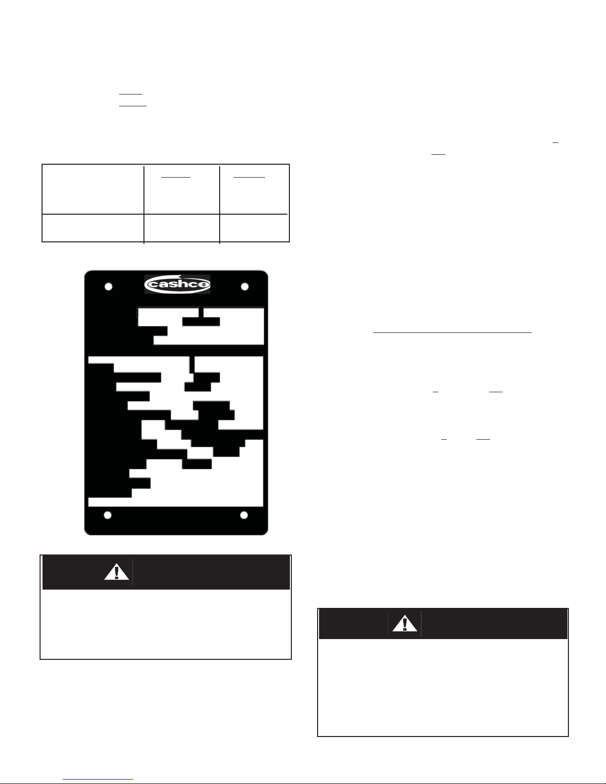
WARNING
Do not pressurize actuator assembly (AA) be yond the
“MAX ACTUATOR PRESSURE” level/value in di cat ed
on the unit’s nameplate (21). Fail ure to heed may
cause catastrophic failure of upper cas ing (1) lead ing
to fl ying parts.
2. Ensure that manual handwheel operator
(MHWO) has handwheel (58.1) backed fully
out by rotating CCW (viewed from above
handwheel (58.1)).
3. Remove cover plate (20) by removing four
screws (36).
4. Remove travel indicator dial (15), dial lens
(14), coverplate (13), bearing fl anges (19) and
bearing (18) by removing three cap screws
(31) using a 3/16" allen key wrench.
5. Units with ATO-FC (Reverse) Action:
a. Disconnect the lower L.H. rod end (9) from
en gage ment with the lever arms (5) by
removing shoulder bolt (40) and lock nut
(46). It will be necessary to re move stem
(Ranger (7), Premier (3.2)) “wind up” as
described in Sec tion V.B.4.
b. Swing the lever arms (5) down against
the travel stop screw (35); this “opens”
valve plug (6)/disc (3.1).
c. Loosen lower upstop jam nut (43) from
securing upstop washer (54); back nut
(43) to the root of its threads on push rod
(10).
d. The upper R.H. rod end (8), lower L.H. rod
end (9), and push rod (10) act to geth er as
a turnbuckle; the upper end is standard
right-hand thread ed while the lower end is
left-hand thread ed. To en sure max i mum
and equal en gage ment of rod ends (8,9)
to the push rod (10), it is rec om mend ed
that the link age (8,9,10) be fully en gaged
and then re ad just ed as a safety pre cau tion.
CAUTION
Unequal engagement adjustment of rod ends (8,9) and
push rod (10) can cause failure of a rod end (8,9)-topush rod (10) connection.
a. If this occurs during bench main te nance, the
parts (8,9,10) could snap apart and cause
per son al injury.
b. If this occurs during installed operation, con-
trol func tion would be lost.
18
IOM-48
Page 19

e. Loosen lower L.H. rod end (9) jam nut (44)
by rotating CW (viewed from above); this
nut (44) is “left-handed”. Back nut (44) to
the root of its threads on push rod (10).
f. Using a suitable tool to prevent lower L.H.
rod end (9) from rotating, rotate push rod
(10) CCW (viewed from above) until up per
end of push rod (10) is fully en gaged with
upper R.H. rod end (8). NOTE: If lower L.H.
rod end (9) reaches full en gage ment with
low er push rod (10) end fi rst, remove tool
se cur ing against ro ta tion, and allow lower
L.H. rod end (9) to rotate with push rod
(10). Once upper end of push rod (10) is
fully en gaged with upper R.H. rod end (8),
rotate lower L.H. rod end (9) CW (viewed
from above) until it is fully engaged.
g. Provide a temporary air supply with an
inline ad just able airset to the ac tu a tor
upper cas ing (1) connection.
h. Reference the name plate (21) at tached
to the cover plate (20) that is fas tened to
the arm hous ing (4). De ter mine the bench
set ting from the name plate (21).
i. Pres sur ize the ac tu a tor (AA) to the lower
val ue of the benchset range pres sure
in di cat ed on the name plate (21).
j. While holding low er L.H. rod end (9) out
of way, lift lever arms (5) up as far as
pos si ble (this will close plug (Rang er (5))/
disc (Pre mier (3.1)).
k. Rotate lower L.H. rod end (9) as re quired
to orient the holes of the rod end (9) and
the lever arms (5) in the same plane.
Swing low er L.H. rod end (9) be tween
the lever arms (5).
l. Rotate the push rod (10) CW (viewed
from above) lowering the lower L.H. rod
end (9) until it’s hole is centered with the
lever arm (5) holes. Center lever arms (5)
with in arm housing’s (4) transverse axis;
i.e. center over trav el stop screw (35).
m. Reinstall the shoulder bolt (40) through
the lever arm (5) and lower L.H. rod end
(9) holes. Finger-tight en lock nut (46) onto
shoul der bolt (40). Using a 1/4" allen key
wrench to secure the head of shoul der
bolt (40), torque wrench-tighten nut (46)
to 15-20 ft-lbs (20-27 N-m).
n. Tighten lower L.H. jam nut (44) down until
locked against lower L.H. rod end (9); nut
(44) is “left-handed”.
o. Add approximately 6 psig (0.4 Barg) to the
actuator’s (AA) lower value of benchset
range. This will extend the actuator stem/
push rod sub-assembly (8, 9, 10, 43, 43,
43, 44, 54) downwards to al low loos en-
ing double jam nuts (43) on top side of
uptravel stop washer (54).
p. Release air pressure down to the lower
value of benchset range.
q. Rotate lower jam nut (43) to raise uptravel
stop wash ers (54) until the gap clearance
between the lower casing (2) and the
top side of the washer (54) is 1/8"±1/16"
(3mm±1.5mm).
r. Repressurize actuator (AA) to level as
indicated in Article 5.o. above. Tighten
the lower of the two upper jam nuts (43)
until it is tight, and secures the uptravel
stop washer (54). Tighten the upper of
the two upper jam nuts (43) down to
secure the double jam nut (43) locking
effect. Retighten lower jam nut (43) on
un der neath side of washer (54).
s. Release all air pressure from actuator
upper casing (1). Repressurize slowly to
confi rm that as the pressure reaches the
lower value of the benchset range (see
Article 5.i. previous), the actuator stem/
push rod sub-assembly (8, 9, 10, 43, 43,
43, 44, 54) begins to move. If move ment
is prematurely occurring (i.e. move ment
at less than the lower benchset range
val ue), the length of the actuator stem
sub-as sem bly (8, 9, 10, 43, 43, 43, 44,
54) must be short ened. Re peat pro ce dure
from Article 5.a. through to this Ar ti cle. If
move ment is late (i.e. move ment at more
than the lower benchset range value), the
length of the actuator stem sub-assembly
(8,9,10,43,43,43,44,54) must be length ened (i.e. increased). Re peat procedure
from Article 5.a. through to this Article. It
is recommended that ad just ment of ac tu a tor stem sub-assembly (8, 9, 10, 43,
43, 43, 44, 54) be made in one rev o lu tion
of push rod (10) increments. Re peat as
nec es sary.
t. Slowly increase air pressure in upper cas-
ing (1) until reaching the higher value of
the benchset range; i.e. pres sur ize only
until plug (Ranger (5))/disc (Premier (3.1))
is in the full open position.
u. Release all air pressure in actuator upper
casing (1). Repeat Article 5.t above and
this article, cycling valve unit (AA, BA)
closed-open-closed-open-closed sev er al
times.
v. With valve plug (Ranger (5)) / disc (Pre mier
(3.1)) in “full closed” position, re in stall
bearing (18), bearing fl anges (19), cover-
plate (13), dial lens (14) and dial (15) with
three cap screws (31). NOTE: Position
IOM-48
19
Page 20

dial (15) such that travel in di ca tor (16)
shows “0°” travel before fully tightening
screws (31).
w. Completion to this point completes the
benchset range adjustment. Proceed
to Subsection VI.C. to adjust 90° travel
stop.
6. Units with ATC-FO (Direct) Action:
a. Disconnect the lower L.H. rod end (9)
from en gage ment with the lever arms (5)
by removing shoulder bolt (40) and lock
nut (46).
b. Swing the lever arms (5) down and as
close as possible to the travel stop screw
(35); this “closes” valve plug (6) / disc
(3.1). Ensure that the “closed” position
is reached by observing actual plug (6) /
disc (3.1) position.
c. Loosen lower upstop jam nut (43) from
securing upstop washer (54); back nut
(43) to the root of its threads on push rod
(10).
d. The upper R.H. rod end (8), lower L.H. rod
end (9), and push rod (10) act to geth er as
a turnbuckle; the upper end is stan dard
right-hand thread ed while the low er end is
left-hand thread ed. To ensure max i mum
and equal en gage ment of rod ends (8,9) to
the push rod (10), it is rec om mend ed that
the link age (8,9,10) be fully en gaged and
then re ad just ed as a safety pre cau tion.
CAUTION
Unequal engagement adjustment of rod ends (8,9) and
push rod (10) can cause failure of a rod end (8,9)-topush rod (10) connection.
a. If this occurs during bench maintenance, the
parts (8,9,10) could snap apart and cause
per son al injury.
b. If this occurs during installed operation, con trol
func tion would be lost.
e. Loosen lower L.H. rod end (9) jam nut (44)
by rotating CW (viewed from above); this
nut (44) is “left-handed”. Back nut (44) to
the root of its threads on push rod (10).
f. Using a suitable tool to prevent lower L.H.
rod end (9) from rotating, rotate push rod
(10) CCW (viewed from above) until up per
end of push rod (10) is fully en gaged with
upper R.H. rod end (8). NOTE: If lower L.H.
rod end (9) reaches full en gage ment with
lower push rod (10) end fi rst, remove tool
se cur ing against ro ta tion, and allow lower
L.H. rod end (9) to rotate with push rod
(10). Once upper end of push rod (10) is
fully en gaged with upper R.H. rod end (8),
rotate lower L.H. rod end (9) CW (viewed
from above) until it is fully en gaged.
g. Provide a temporary air supply with an
inline ad just able airset to the actuator
up per casing (1) connection.
h. Reference the nameplate (21) at tached
to the cover plate (20) that is fastened to
the arm housing (4). De ter mine the bench
setting from the nameplate (21).
i. Rotate lower L.H. rod end (9) until the rod
end (9) and the lever arm’s (5) holes are
in the same plane.
j. Loosen jam nut (45) and rotate downtra-
vel stop screw (35) out by ro tat ing CCW
(viewed from below screw’s (35) head)
until just barely engaged in arm hous ing
(4).
k. Pressurize actuator (AA) to the higher
value of the benchset range pressure
in di cat ed on the nameplate (21), while
“guid ing” the lower L.H. rod end (9) hub
to its proper position between the lever
arms (5).
l. Pressurize actuator (AA) to a level as
indicated by “C” pressure in table that
follows according to the formula: “A” +
“B” = “C”.
Benchset Higher Value Adder Loading
Range of Benchset Value – Pressure –
Range - “A” “B” “C”
_____ psig ____ psig 2 psig ____ psig
____ Barg ____ Barg .14 Barg ____ Barg
m. Adjust the push rod (10) by rotating CW
(viewed from above) until the holes of the
lever arms (5) and the lower L.H. rod end
(9) are centered and the valve is in the
“closed” position.
n. Reinstall the shoulder bolt (40) through
the lever arm (5) and lower L.H. rod end
(9) holes. Finger-tighten lock nut (46) onto
shoulder bolt (40). Using a 1/4" allen key
wrench to secure the head of shoul der
bolt (40), torque wrench-tighten nut (46)
to 15-20 ft-lbs (20-27 N-m).
o. Loosen double jam nuts (43,43) on top
side of uptravel stop washer (54).
p. With valve in “closed” position, reinstall
bearing (18), bearing fl anges (19), cov-
erplate (13), dial lens (14) and dial (15)
with three cap screws (31). NOTE: Po-
si tion dial (15) such that travel in di ca tor
20
IOM-48
Page 21

(16) shows “0°” travel (no “bright or ange”
show ing from indicator (16))before fully
tight en ing screws (31).
q. Fully release air pressure in actuator
(AA). Observe position of valve on travel
in di ca tor (16). Travel should be short of
“full open”; i.e. 90° rotation.
1. Travel short of 90°. Adjust the push
rod (10) by rotating CCW (viewed from
above) until the travel reaches 90° as
shown by travel indicator (16).
2. Travel beyond 90°. Adjust the push
rod (10) by rotating CW (viewed from
above) until the travel is reduced to
90° as shown by the travel indicator
(16).
r. Rotate lower jam nut (43) to raise uptravel
stop wash ers (54) until the gap clearance
between the lower casing (2) and the
top side of the washer (54) is 1/8"±1/16"
(3mm±1.5mm).
s. Repressurize actuator (AA) to upper val ue
of benchset range. Tighten the lower of
the two upper jam nuts (43) until it is tight,
and secure the uptravel stop washer (54).
Tighten the upper of the two upper jam
nuts (43) down to secure the double jam
nut (43) locking effect. Retighten lower
jam nut (43) on underneath side of wash er
(54).
t. Tighten lower L.H. jam nut (44) down until
locked against lower L.H. rod end (9); nut
(44) is “left-handed”.
u. For Premier EZO and Premier Unlined
ONLY. Ref er ence VI.C.2. for procedure
to adjust downtravel stop screw (35).
v. Release all air pressure in actuator upper
casing (1). Repeat loading-unloading to
cycle the valve unit (AA, BA). Repeat
adjustments as necessary.
w. Completion to this point completes the
benchset range adjustment. Proceed to
the next subsection (VI.C.) to adjust 90°
travel stop, if necessary.
b. Rotate downtravel stop screw
(35) CCW (viewed from below
screw (35)) until 90° rotation is
reached on the travel indicator
(16).
c. Retighten jam nut (45).
2. Travel beyond 90°. Hub of lower L.H.
rod end (9) may or may not be touch ing on downtravel stop screw’s (35)
upper end.
a. Loosen jam nut (45) about four
revolutions.
b. Very slowly release air pressure
into actuator (AA) until travel
in di ca tor (16) is showing at 90°.
c. Rotate downtravel stop screw
(35) CW (viewed from below
screw (35)) until the screw’s (35)
upper edge touch es the hub of
lower L.H. rod end (9).
d. Retighten jam nut (45).
2. Units with ATC-FO (Direct) Action:
a. Loosen jam nut (45).
b. Rotate downtravel stop screw (35) CW
(viewed from below screw (35)).
c. Pressurize actuator (AA) slowly until the
travel in di ca tor (16) indicates that travel
is at 0°; the valve should be in the “fully
closed” position.
d. Adjust gap between downtravel stop screw
(35) and hub of lower L.H. rod end (9) as
indicated in table that follows.
e. Retighten jam nut (45).
Product Gap Between L.H. Rod End (9)
Model and Downtravel Stop Screw (35)
Ranger QCT 1/8" ± 1/16" (3.0 mm ± 1.5 mm)
Premier EZO 1/16" ± 1/16" (1.5 mm ± 1.5 mm)
Premier Unlined No gap; i.e. touching
C. 90° Rotation Adjustment:
1. Units with ATO-FC (Reverse) Action:
a. Pressurize actuator (AA) to the higher
value of benchset range. This pressure
should cause 90° rotation as shown by
travel indicator (16).
1. Travel short of 90°. Hub of lower
L.H. rod end (9) may be touching on
downtravel stop screw’s (35) upper
end.
a. Loosen jam nut (45).
IOM-48
21
Page 22
SECTION VII
VII. TROUBLE SHOOTING GUIDE
Reference the IOM of the valve body this actuator is unitized with for additional information on Trouble Shooting.
1. Air leakage.
Possible Causes Remedies
A. Leakage at diaphragm-to-upper casing A1. Overpressure. Check source of air supply and
fl ange. determine if pressure is greater than indicated in
Table 1; reset airset pressure as required.
A2. Tighten casing fl ange bolting (27, 28, 41 & 42)
B. Leakage at handwheel gland-to-upper case. B. Faulty O-ring (62); replace O-ring.
C. Leakage at manual handwheel threads. C. Faulty seal (61); replace thread seal.
D. Leakage around stem on side where yoke D1. Failure of diaphragm (6); replace diaphragm.
bolts to arm housing. D2. Faulty seal (56); replace seal.
SECTION VIII
VIII. ORDERING INFORMATION
NEW REPLACEMENT UNIT vs PARTS "KIT" FOR FIELD REPAIR
To obtain a quotation or place an order, please retrieve the Serial Number and Product Code that was stamped on
the metal name plate and attached to the unit. This information can also be found on the Bill of Material ("BOM"),
aparts list that was provided when unit was originally shipped. (Serial Number typically 6 digits). Product Code
typical format as follows: (last digit is alpha character that refl ects revision level for the product).
–
NEW REPLACEMENT UNIT:
Contact your local Cashco, Inc., Sales Rep re sen ta tive with the Serial Number and Product code.
With this information they can provide a quotation
for a new unit including a complete description,
price and availability.
CAUTION
Do not attempt to alter the original construction of any
unit without assistance and approval from the factory. All
purposed changes will require a new name plate with appropriate ratings and new product code to accommodate
the recommended part(s) changes.
–
7
PARTS "KIT" for FIELD REPAIR:
Contact your local Cashco, Inc., Sales Rep re sen ta tive with the Serial Number and Product code.
Identify the parts and the quantity required to repair
the unit from the "BOM" sheet that was provided
when unit was originally shipped.
NOTE: Those part numbers that have a quantity indicated
under "Spare Parts" in column "A” refl ect minimum
parts required for inspection and rebuild, - "Soft
Goods Kit". Those in column “B” include minimum
trim replacement parts needed plus those "Soft
Goods" parts from column "A".
If the "BOM" is not available, refer to the crosssectional drawings included in this manual for part
identifi cation and selection.
A Local Sales Representative will provide quotation
for appropriate Kit Number, Price and Availability.
The contents of this publication are presented for informational purposes only, and while every effort has been made to ensure their accuracy, they are not to be construed as warranties or guarantees, express or implied, regarding the products or services described herein or their use or applicability. We reserve the right to modify
or improve the designs or specifi cations of such product at any time without notice.
Cashco, Inc. does not assume responsibility for the selection, use or maintenance of any product. Responsibility for proper selection, use and maintenance of any
Cashco, Inc. product remains solely with the purchaser.
22
IOM-48
Page 23
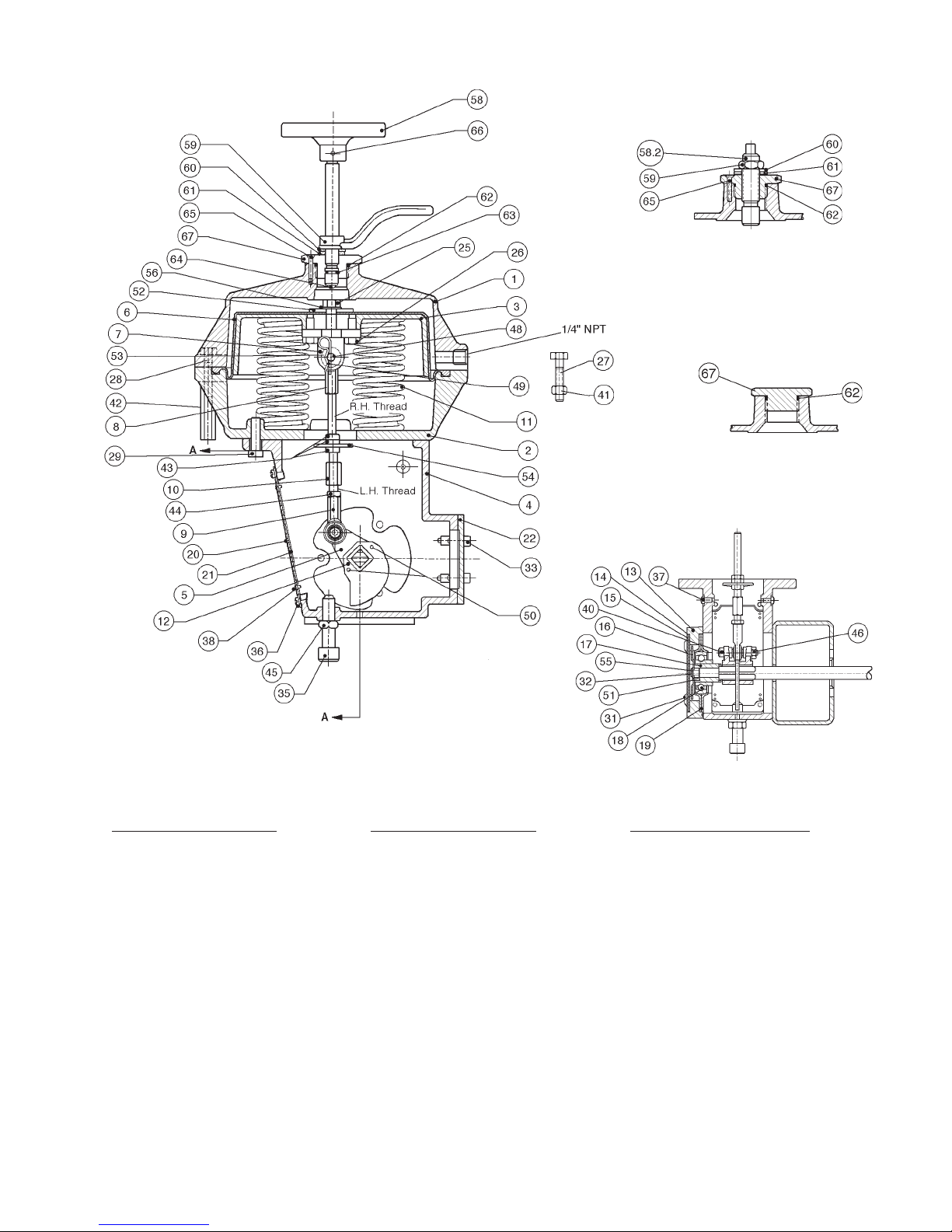
ADJUSTING SCREW ASSEMBLY
Not available on Air to Close-Fail Open Rangers
ACTUATOR PLUG
Available on Premier Butterfl y
Valves ONLY
BASIC 48 ACTUATOR
Shown Air to Open
ITEM NO. DESCRIPTION
1. Upper Case
2. Lower Case
3. Piston
4. Arm Housing
5. Arm
6. Diaphragm
7. Clevis
8. Rod End (R.H.)
9. Rod End (L.H.)
10. Push Rod
11. Spring
12. Cam
13. Cover Plate
14. Dial Lens
15. Travel Indicator Dial
16. Travel Indicator
17. Indicator Spacer
18. Ball Bearing
19. Bearing Flange
20. Cover Plate
21. Name Plate
IOM-48
ITEM NO. DESCRIPTION
22. Housing Cover
25. Pivot Screw
26. Hex. Head Cap Screw
27. Hex. Head Cap Screw
28. Hex. Head Cap Screw
29. Hex. Head Cap Screw
31. Button Head Cap Screw
32. Button Head cap Screw
33. Socket Head Cap Screw
35. Socket Head Stop Screw
36. Fillister Head Machine Screw
37. Fillister Head Machine Screw
38. Drive Screw
40. Bolt Shoulder
41. Nut
42. Extension Nut
43. Jam Nut
44. Jan Nut (L.H.)
45. Jam Nut
46. Lock Nut
48. Clevis Pin
SECTION “A-A”
ITEM NO. DESCRIPTION
49. Hairpin
50. Spring Pin
51. Spring Pin
52. Diaphragm Washer
53. Washer
54. Stop Washer
55. Internal Lock Tooth Washer
56. Seal
58. Handwheel Subassembly
or Adjusting Screw
59. Locking Lever or Nut
60. Washer
61. Thread Seal
62. O-Ring (Gland to Upper Case)
63. O-Ring (Handwheel to Gland)
64. Ball
65. Self-Tapping Screw
66. Pin (Spring)
67. Handwheel Gland or
Actuator Plug
23
Page 24
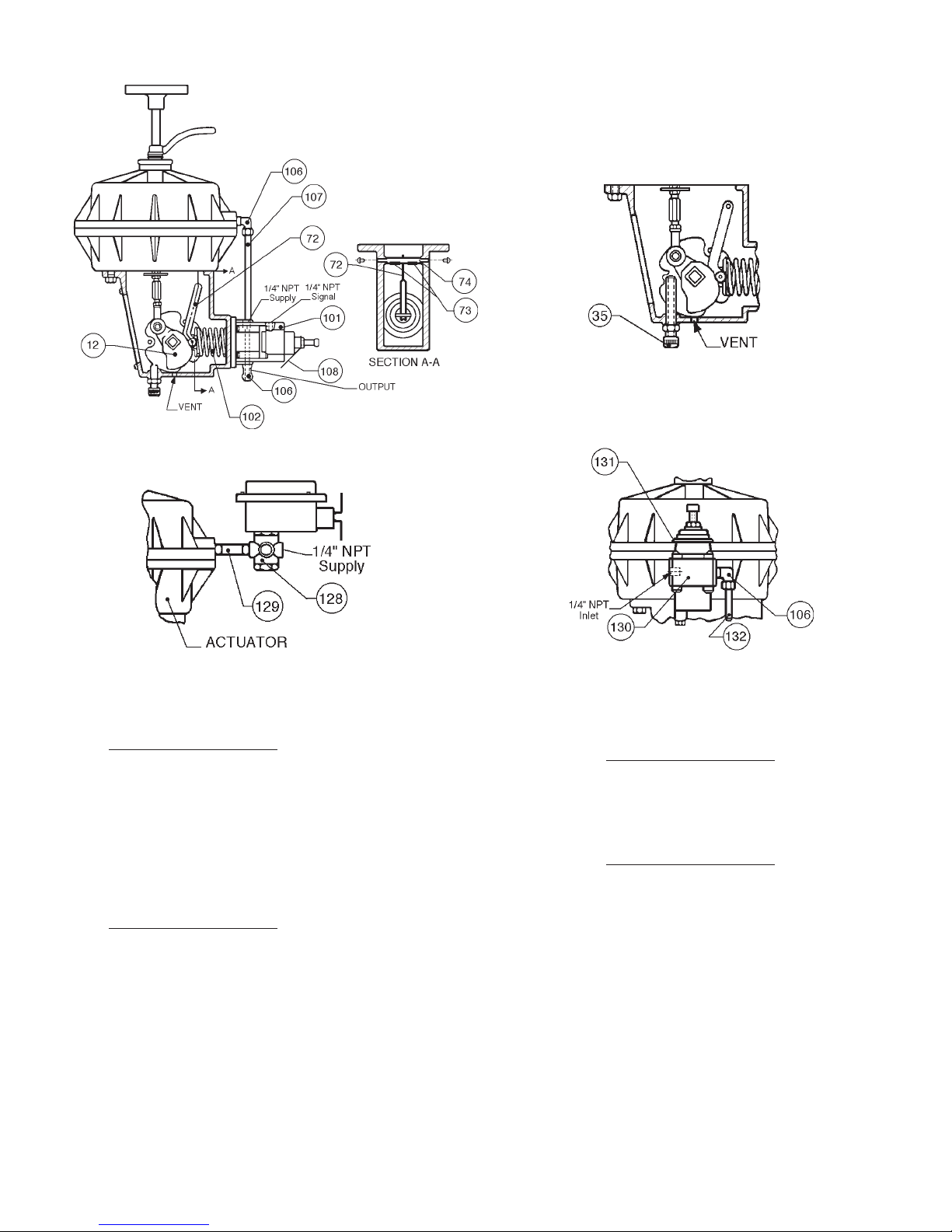
73N-B POSITIONER
STOP SCREW
SOLENOID VALVE
73N-B POSITIONER
ITEM NO. DESCRIPTION
72 Feedback Linkage Subassembly
73 Feedback Linkage Spacer
74 Feedback Linkage Pivot Shaft
101 Positioner
102 Range Spring
106 Tube Fittings (Elbow)
107 Output Tube
108 Name Plate
SOLENOID VALVE
ITEM NO. DESCRIPTION
128 Solenoid Valve
129 Nipple
Cashco, Inc.
P.O. Box 6
Ellsworth, KS 67439-0006
PH (785) 472-4461
Fax. # (785) 472-3539
www.cashco.com
email: [email protected]
Printed in U.S.A. 48-IOM
Cashco GmbH
Handwerkerstrasse 15
15366 Hoppegarten, Germany
PH +49 3342 4243135
Fax. No. +49 3342 4243136
www.cashco.com
Email: [email protected]
Cashco do Brasil, Ltda.
Al.Venus, 340
Indaiatuba - Sao Paulo, Brazil
PH +55 11 99677 7177
Fax. No.
www.cashco.com
Email: [email protected]
AIR SUPPLY REG U LA TOR
AIR SUPPLY REGULATOR
ITEM NO. DESCRIPTION
130 Air Supply Regulator
131 Mounting Bracket
132 Supply Tube
GUAGES (Not Shown)
ITEM NO. DESCRIPTION
135 Signal Guage
137 Output Gauge
138 Branch Tee
139 Reducing Bushing
 Loading...