

Page 1

INSTALLATION, OPERATION & MAINTENANCE MANUAL (IOM)
IOM-31-N
05-14
MODEL 31-N
Pressure Reducing Service Regulator
SECTION I
I. DESCRIPTION AND SCOPE
The Model 31-N is a pressure reducing service regulator used to control downstream (outlet or P2) pressure to levels
between 2" – 16 “WC (50–400 mm H2O). Sizes are 1/2" 3/4”, 1", 1-1/2" and 2" (DN15, 20, 25, 40 and 50).
The unit is designed for gaseous service only.
Refer to Technical Bulletin 31-N-TB for sizing, application and selection recommendations.
WARNING
1. Model 31-N does not include an internal relief mech a nism. Overpressure protection requires use of a downstream
safety relief valve or rupture disc.
2. User to determine acceptance of non-relieving design by federal, state, and/or local codes.
3. IF GAS IS DETECTED BY SMELL, CONTACT YOUR GAS COMPANY IMMEDIATELY.
4.
User to comply with instructions, operating re quire ments and maintenance requirements located herein the “IOM-31-N”.
II. INSTALLATION
1. An inlet block valve should always be installed.
An outlet block valve is recommended.
2. If service application is continuous such that
shut down is not readily accomplished, it is
rec om mend ed that an outlet block valve and a
manual bypass valve be installed.
3. Pipe unions are recommended to be installed to
allow removal from piping. Trim can be changed
without removal from pipeline.
4. An outlet pressure gauge should be located
ap prox i mate ly 10 pipe diameters downstream,
and within sight.
5. All installations should include a downstream
re lief device if the inlet pressure could exceed the
pressure rating of any downstream equipment.
A downstream safety relief valve or a rupture
disc is absolutely required if the inlet P1
pres sure exceeds 100 psig (6.9 Barg) under
any normal or upset conditions.
SECTION II
CAUTION
Installation of adequate overpressure pro tec tion is recommended to pro tect the reg u la tor from overpressure and
all down stream equip ment from damage in the event of
regulator failure.
WARNING
The maximum outlet pressure listed on the name plate is
the “upper operative limit” for the sensing di a phragm.
Higher pressures could damage the internals. (Field hy dro stat ic or pneumatic pressure tests fre quent ly destroy
diaphragms. DO NOT HY DRO STAT IC OR PNEUMATIC
PRESSURE TEST THRU AN IN STALLED UNIT EX POS ING
THE OUTLET POR TION OF THE REGULATOR TO PRES SURES GREATER THAN 50 PSIG (3.45 BARG) FAIL URE
TO HEED MAY RESULT IN CAT A STROPH IC FAIL URE WITH
FLYING PARTS AND POSSIBILITY OF PER SON AL INJURY!
ISO LATE FROM TEST.)
CAUTION
For welded installations, all internal trim parts, seals and
diaphragm(s) must be removed from reg u la tor body prior to
welding into pipeline. The heat of fusion welding will dam age non-metallic parts if not re moved. NOTE: This does
not apply to units equipped with extended pipe nip ples.
Page 2
6. Clean the piping of all foreign material including
chips, welding scale, oil, grease and dirt before
in stall ing the regulator. Strainers are rec om mend ed.
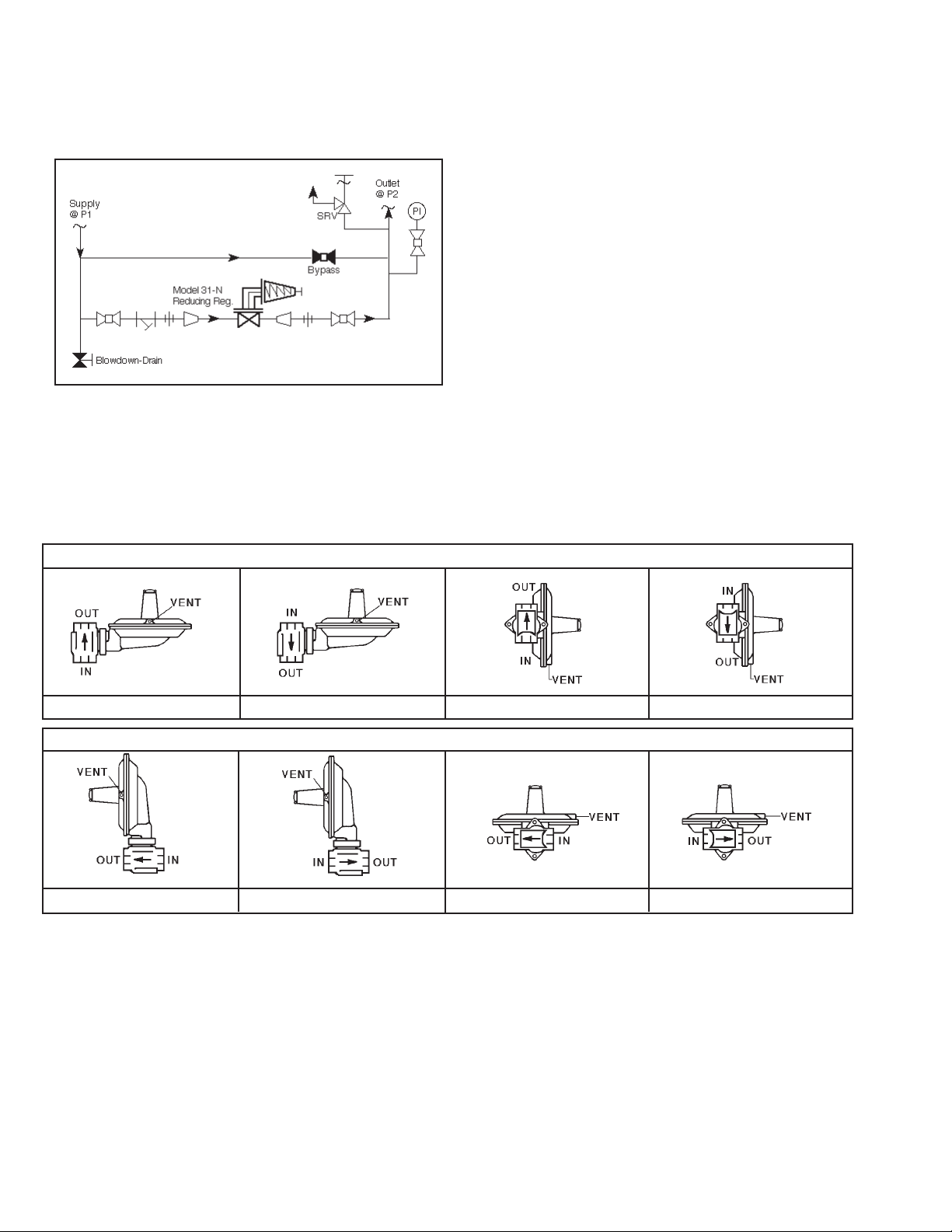
Figure 1
Recommended Piping Schematic For
Pressure Re duc ing Station
7. In placing thread sealant on pipe ends prior to
en gage ment, assure that excess material is
re moved and not allowed to enter the regulator
upon startup.
8. Flow Direction: Install so the fl ow direction match es
the arrow cast on the regulator body.
9. Refer to Figure 2. Regulator may be rotated
around the pipe axis 360°, and may be installed
in a horizontal or vertical pipeline. Four orientation/
arrangement assembly positions are standard. Orient to prevent the spring chamber vent hole from
collecting rainwater or debris. Reorient ac tu a tor
around the stem axis 360° if nec es sary.
10. Regulators are not to be direct buried un der ground.
11. For insulated piping systems, recommendation is
to not insulate regulator.
12. Cashco does not recommend fi eld welding on
the body of the regulator. If weld connections are
desired, specify Opt-32, extended plain end pipe
nipples.
FOR VERTICAL PIPING
Position 1
Position 1
Position 2
FOR HORIZONTAL PIPING
Position 2
III. PRINCIPLE OF OPERATION
1. Refer to internals drawings Figures 5 thru 8.
2. Internal trim movement occurs as pressure vari a tions register on the diaphragm. The registering
pressure is the controlled outlet pressure, P2, or
down stream pressure. The range spring opposes
Figure 2
SECTION III
Position 3
Position 3
up wards movement of the diaphragm due to the
P2 pressure. As outlet pressure drops, the range
spring pushes the diaphragm down, opening the
regulator’s port via the linkage lever travel. As
outlet pressure increases, the diaphragm pushes
up against the range spring and the port closes.
Position 4
Position 4
IOM-31-N2
Page 3

3. Model 31-N includes a linkage lever in its mech a nism. The linkage lever allows the regulator to
operate fl ow-to-open (FTO) and provides plug
travel multiplication thru the lever length ratio.
5. Aspiration (jet) effect is developed by properly
locating the “windows” of the loading ring. When
properly po si tioned, a high velocity path is in tro duced. This causes a corresponding decrease in
IV. STARTUP
static pressure to be de vel oped at a location that
allows this decreased pressure to register into the
lower case and beneath the diaphragm. The net
result is to pull the diaphragm down and open the
valve port, providing higher unit capacity.
6. A complete diaphragm failure will cause the reg u la tor to fail open.
SECTION IV
1. Assure that the proper range spring is indicated
to be within the regulator by inspection of the
unit’s name plate. Apply setpoint pressures that
are only within the stated range.
2. When stating direction of rotation of the ad just ment
screw, the view is with respect to looking down
towards the closing cap or its normal lo ca tion.
3. Start with the block valves closed. A bypass
valve may be used to maintain outlet pressure
in the down stream system without changing the
fol low ing steps.
4. Remove closing cap on top of spring chamber.
Relax the range spring by turning the adjustment
screw CCW a minimum of three (3) full rev o lu tions.
This reduces the outlet (downstream) pres sure
setpoint.
5.
Crack open the outlet (downstream) block valve.
6. Slowly open the inlet (upstream) block valve ob serv ing the outlet (downstream) pressure gauge.
Partially close off the bypass valve, if open. De ter mine if the regulator is fl owing. If not, slowly
rotate the regulator adjustment screw CW until
fl ow begins.
7. Continue to slowly open the inlet (upstream) block
valve until fully open.
8. Continue to slowly open the outlet (downstream)
block valve, especially when the downstream piping system isn’t pressurized. If the outlet (down stream) pres sure exceeds the desired pressure,
close the inlet (up stream) block valve fi rst, then
the outlet (downstream) block valve, and go to
Step 4, then return to Step 6.
9. When fl ow is established steady enough that the
outlet (downstream) block valve is fully open, begin
to slowly close the bypass valve if installed.
10. Develop system fl ow to a level near its expected
normal rate, and reset the regulator setpoint per
Section VII.
11. Reduce system fl ow to a minimum level and ob-
serve setpoint. Outlet pressure may rise from the
set point of Step 10. The maximum rise in outlet
pressure on decreasing fl ow should not exceed the
stated upper limit of the range spring by greater than
10%; i.e. 5.5–8.0 “WC (140–200 mmH2O) range
spring, at low fl ow the outlet pressure should not
exceed 8.8 “WC (224 mmH2O). If it does, consult
factory.
V. SHUTDOWN
1. On systems with a bypass valve, and where system pressure is to be maintained as the reg u la tor
is shut down, slowly open the bypass valve while
closing the inlet (up stream) block valve. Fully
close the inlet (up stream) block valve. (When on
bypass, the system pres sure must be con stant ly
observed and manually reg u lat ed.) Close the outlet
(downstream) block valve.
IOM-31-N
SECTION V
WARNING
Do not walk away and leave a bypassed reg u la tor
un at tend ed.
2. If the regulator and system are to both be shut down, slowly close the inlet (upstream) block
valve. Close the outlet (downstream) valve only
if regulator removal is required.
3
Page 4
SECTION VI
VI. MAINTENANCE
A. General:
WARNING
SYSTEM UNDER PRESSURE. Prior to performing any
maintenance, isolate the regulator from the system and
relieve all pressure. (Including the External Sensing
line when specifi ed.) Failure to do so could result in
personal injury.
1. Maintenance procedures hereinafter are based
upon removal of the regulator from the pipeline
where installed.
2. Owner should refer to owner’s procedures for
re mov al, handling and cleaning of re us able
parts, the dis pos al of non-reusable parts, i.e.
gaskets, suitable sol vents, etc.
3. If desired, gaskets may be oiled, or coated with
gasket sealant or thread sealing com pound,
provided the sealant is compatible with the fl u-
id. (See below for “oxygen cleaned” valves.)
4. Valves originally supplied as “special cleaned”
(Opt-56) are assembled using special seal ant,
Fluorolube GR-3621, or equivalent. Cash co,
Inc., rec om mends fol low ing factory cleaning
specifi cation #S-1542, or equiv a lent. Contact
factory for details.
5. When directions such as upwards, down wards,
leftwards or rightwards are given, they are with
respect to Figures 5 and 6.
When counter clockwise (CCW) or clock wise
(CW) ro ta tions are indicated, they are with
respect to:
a. Spring Chamber – as viewed from above
looking down towards the closing cap or
its normal location.
b. Body – as viewed looking into the body
cavity with the upper case assembly re moved.
B. Diaphragm Replacement:
WARNING
SPRING UNDER COMPRESSION. Prior to re mov ing upper case, relieve spring compression by removing the
ad just ing screw. Failure to do so may result in fl ying parts
that could cause personal injury
1. Install the body (1) in a vise with the spring
chamber (4) directed upwards.
2. Remove closing cap (5). Relax range spring
(17) by turning adjustment screw (18) CCW
until removed from spring cham ber (4); count
number of full revolutions and record below.
No. of revolutions to remove ad just ment
screw (18) ____________________ .
3. Paint or embed a match mark between lower
case (3) and spring chamber (4) at fl ange
O.D.
4. Remove all diaphragm fl ange nuts (10) and
screws (9).
5. Remove spring chamber (4) and range spring
(17).
6. Pry up the edges of the diaphragm (12) from
around the pe rim e ter of the lower case (3)
diaphragm fl ange to assure that the diaphragm
(12) is not “sticking” to the lower case.
7. Grasp stop post (19) and with hand carefully
lift up wards and to the right to disengage linkage lever (21) from cir cu lar opening of lower
di a phragm plate (20). Fully remove diaphragm
sub-assembly (DSA) from lower case.
8. Place the “ear” of the lower diaphragm plate
(20) into a soft jawed vise and fully secure,
with stop post (19) pointed upwards. Place a
wrench on the hex surface of stop post (19)
and loosen by rotating CCW (viewed from
above).
.
1
Product of Fisher Scientifi c Company
9. Grasp upper diaphragm plate (13) with fi n gers
and continue to loosen stop post (19) until removal. Finger remove washer (16), and nylon
bushing (15). Lift upper diaphragm plate (13),
together with stuck-on diaphragm (12) away
from lower diaphragm plate (20), and place
on bench top.
IOM-31-N4
Page 5

10. While holding upper diaphragm plate (13)
by palm of hand, hand-pull diaphragm (12)
away from upper di a phragm plate (13).
NOTE: The diaphragm (12) is adhered to the
upper di a phragm plate (13) with adhesive.
Rotate and repeat until the diaphragm (12)
is fully re moved. Discard used diaphragm
(12). Re move remaining ad he sive from
upper di a phragm plate (13).
11. Examine upper plate (13) for bending or
distortion. Re place if deformation is present.
12. Spread a thin layer of compatible adhesive (DuPont 732 or equal) onto the
cleaned upper pressure plate (13), staying away from the edges approximately
1/2" (12 mm). Place a new di a phragm (12)
down onto a fl at surface with the di a phragm’s
(12) fl ange edges up, forming a “bowl”
with a hole in the center. Carefully lift the
upper diaphragm plate (13), invert 180°,
and lower into the diaphragm (12) “bowl”
with the ad he sive meeting the diaphragm
(12); align the upper diaphragm plate (13)
as concentrically as able. Carefully lift the
adhered parts (12)(13) and invert 180°.
Align the diaphragm (12) hole and upper
diaphragm plate (13) hole con cen tri cal ly.
Work out any “bubbles” formed be tween the
diaphragm (12) and the upper di a phragm
plate (13) using a fl at tool as nec es sary.
Once aligned, set adhered parts (12)(13)
back down to allow adhesive approximately
30 minutes setting/drying time.
13. Place the adhered diaphragm (12) and the
upper diaphragm plate (13) back onto the
lower diaphragm plate (20) still resting in
the vise. Position/align the diaphragm (12)
with respect to the lower diaphragm plate
(20) as indicated in Figure 3; failure to align
properly may cause poor unit performance.
Figure 3
16. Position the diaphragm sub-assembly
(DSA) to wards the rightwards of center of
the lower case (3) with the opening of the
lower di a phragm plate (20) oriented per pen dic u lar to the linkage lever (21). Insert
the linkage lever (21) thru the opening of
the lower diaphragm plate (20). Align the
bolt holes of diaphragm (12) with the bolt
holes of the lower case (3).
17. Place range spring (17) over stop post
(19), and align properly by setting spring
(17) over washer (16) and nylon bushing
(15) so that the spring (17) rests on upper
diaphragm plate (13).
14. Set nylon bushing (15) into hole in the top
15. Insert stop post (19) thru the center opening
IOM-31-N
of the upper diaphragm plate (13). Place
washer (16) on top of nylon bush ing (15).
of stacked parts (16, 15, 13, 12) and engage
threaded end of stop post (19) into lower
diaphragm plate (20). Carefully tighten stop
post (19) to ensure concentricity of stacked
parts (16, 15, 13, 12). Tighten stop post
(19) to 18–20 in-# (2.0–2.3 N-M) torque.
This com pletes di a phragm sub-as sem bly
(DSA); re move from vise.
18. Clean threads of spring chamber (4) “barrel” thor ough ly using suitable solvent.
19. Set spring chamber (4) onto lower case (3)
align ing matchmarks of Step 3 previous.
20. Insert screws (9) into fl ange bolt holes.
En gage nuts (10). Align and push nuts
(10) up against the un der neath side of
the lower case (3) fl ange, ensuring that
the “tips” of the nuts are not improperly
positioned due to the small “lugs” on the
lower case fl ange. Hand-tighten all screws
(9) and nuts (10).
5
Page 6

21. In an alternating cross-pattern, tighten screws
(9) in one revolution increments. Repeat
pattern until torque reaches 25–30 in-#
(2.8–3.4 N-M).
22. Engage adjustment screw (18) the same
num ber of revolutions as recorded from Step
2 previous.
23. Remove and replace closing cap gasket (6).
Re place closing cap (5) and fi nger tighten
only.
C. Trim Replacement:
1. Place body (1) into a vise and secure. Paint
or embed a match mark between lower case
(3) and body (1).
2. Loosen both cap screws (11) bolting the ac tu a tor assembly (AA) to the body (1). Holding
the actuator assembly (AA) in hand, rotate cap
screws (11) to removal. NOTE: The ac tu a tor
assembly (AA) may be rotated around the
stem (24) axis during this procedure.
3. Place actuator assembly (AA) in a vise or on
a work bench to allow cleaning of the gasket
(8) surface of the lower case (3) with a fl at
tool. Use spray solvent as necessary (do not
im merse).
4. Remove “rubber” seat (27) from end of stem
(24); examine and discard. Place new seat
(27) onto end of stem (24). For sizes 1-1/2"
and 2" (DN40 & 50), a defl ector ring (32) is
included. Ensure the proper orientation of the
defl ector ring (32) when pushing the new seat
(27) into position. (See Figure 6.)
remove. When replacing orifi ce (26) use
pipe sealant PLS-2 or PST Loctite. Rotate
CW to tighten orifi ce (26); tighten to 35–40
ft-# (47.4–54.2 N-M). NOTE: Do not replace
orifi ce (26) without re plac ing seat (27).
8a. Examine glass-fi lled nylon loading ring (25) for
sizes 1/2" thru 1" (DN15 thru 25). This piece
may wear “notches” at the location where the
loading ring (25) touches the orifi ce (26) “hex
points”. It is necessary that the loading ring
(25) be “clamped snugly” to the orifi ce (26);
replace loading ring (25) if fi t is loose.
8b. Examine SST loading ring (33) for sizes
1-1/2" and 2" (DN40 & 50). Assure that the
three impression points (2 rectangular, 1
cir cu lar) are still present; if an impression
point is missing, replace loading ring (33). It
is nec es sary that the loading ring (33) “clamp
snugly” to the orifi ce (26) to prevent rotation;
replace loading ring (33) if fi t is loose.
9. Refer to Figure 4 for proper alignment of
load ing ring (25, 33) split. Using both thumbs,
push the interior walls of the loading ring (25,
33) apart and lower the loading ring (25, 33)
down into the body (1) cavity, and over the
orifi ce (26). Release thumbs. Assure loading
ring (25, 33) “clamps snuggly”. Re peat until
load ing ring (25, 33) is prop er ly located per
Figure 4. The “split” of the loading ring (25)
is factory as sem bled along the body (1) axial
centerline for body sizes 1/2" - 1" (DN15 -
25), and for loading ring (33) at the 21° mark
on the body (1) for body sizes 1-1/2" and 2"
(DN40 & 50). For all body sizes the “split” in
the loading ring (25, 33) is located opposite
the fl ow direction.
5. Return to the body (1) in vise. Observe po si tion
of “split” in loading ring (25, 33) with respect
to proper location as indicated in Figure 4.
Using both thumbs, push the interior walls to
pry apart the split of the loading ring (25, 33),
until the ring (25, 33) slips off the orifi ce (26).
Remove the loading ring (25, 33).
6. Remove the body (1) from the vise. Clean the
gasket (8) recess of the body (1) with a fl at
tool. Solvent clean body (1). Replace body
(1) into vise.
7. Examine orifi ce (26) for damage to the seat-
ing edge. Replace orifi ce (26) if damaged. To
remove orifi ce (26), place a socket over the
orifi ce (26) hex, and rotate CCW to loosen/
10. Place gasket (8) into body (1) recess.
11. Reposition actuator assembly (AA) into po si tion by hand, aligning body (1) bolt holes with
bolt holes in lower case (3). Insert two cap
screws (11) and fi nger tighten in an al ter nat ing
cross pattern.
12. Wrench tighten cap screws (11) in an al ter nat ing cross pattern to a torque of 8–10 ft.-#
(10.8–13.5N-M).
D. Linkage Lever and Stem Replacement:
1. Remove diaphragm sub-assembly (DSA) as
de scribed in Section VI.B., Steps 1 thru 7.
IOM-31-N6
Page 7

BODY SIZES 1/2', 3/4" & 1" (DN15, 20 & 25)
6. Insert linkage pivot pin (23) thru hole in link age lever (21). Simultaneously engage the
linkage lever (21) and the stem (24), and
place pin (23) ends back into the “cradles”
of the pedestal supports of the lower casing
(3), replace washer (37), engage and tighten
both machine screws (22).
7. Reinstall diaphragm sub-assembly (DSA)
and spring chamber (4) as described in
Section VI.B., Steps 16 thru 23.
8. Reinstall actuator assembly (AA) to body (1)
as de scribed in Section VI.C., Steps 11 and
12.
E. Range Spring Replacement:
1. Remove closing cap (5) from spring chamber
(4).
2. Rotate adjustment screw (18) CCW to re mov al.
3. Remove existing range spring (17).
BODY SIZES 1-1/2" & 2" (DN40 & 50)
Figure 4
2. Remove lower casing (3) from body (1) as
de scribed in Section VI.C., Steps 1 and 2.
3. Remove both machine screws (22), washers (37) and retaining link age pivot pin (23).
(See Figure 8.) Lift link age lever (21) from
its position of en gage ment with stem (24)
bringing linkage pivot pin (23) along. Remove
pin (23) and inspect for wear, bend ing, etc.
Replace pin (23) if re quired.
4. Inspect linkage lever (21) for bending, dis tor tion, etc. Replace lever (21) if required.
5. Withdraw stem (24) through the neck of the
lower case. Inspect stem to assure that there
is no bend ing in the "slot" area where the
stem and linkage lever (21) engage. Replace
stem if there are any signs of bending or
friction in the stem guide or engagement
zones. NOTE: If regulator has external
sensing - replace the o-ring (44). Re-insert
stem back into lower casing.
4. Install new range spring (17) (refer to Table
2).
5. Put thread locking compound on threads of
spring chamber (4) and on adjustment screw
(18).
6. Engage adjustment screw (18) into spring
cham ber (4) by rotating CW until the range
spring (17) begins to compress.
7. Shop calibrate the setpoint per Section VII.
8. Remove old nameplate (28) and drive screws
(29); install new nameplate with correct range
spring indicated.
IOM-31-N
7
Page 8

SECTION VII
VII. SETPOINT ADJUSTMENT/CAL I BRA TION
1. Establish fl ow thru the regulator, preferably a
relatively low fl ow rate, approximately 50 SCFH.
2. Remove closing cap (6) by rotating CCW.
3. If P2 outlet pressure is less than desired, rotate
ad just ment screw (18) CW; if higher than desired,
rotate ad just ment screw (18) CCW.
SECTION VIII
VIII. TROUBLE SHOOTING GUIDE
1. Variation in outlet P2 pressure.
Possible Cause Remedy
A. Oversized valve, insuffi cient rangeability. A1.
4. Reinstall closing cap (6) using pipe joint lubricant/
sealant on threads; fi nger tighten only.
5. Increase fl ow rate to near maximum. Check for
ad e quate P2. Repeat Steps 2 thru 4. as required.
NOTE: At higher fl ow rates, removal of the clos-
ing cap (6) can induce an instability. If this occurs,
make adjustment, and quickly replace closing cap
(6), then observe the new setpoint.
Check actual fl ow conditions; consider use of smaller
orifi ce.
A2.
Reduce P1 pressure if possible.
B. Undersized valve, insuffi cient rangeability. B1.
C. High Inlet P1 pressure. C. Reduce P1 pressure to 60 psig (4.14 Barg) or lower.
D. Loading ring is “loose”. D. Replace loading ring.
E. Variation of Inlet P1 pressure. E. P2 pressure setpoint will vary as P1 pressure varies;
F. Dirty service gas; unit becomes unresponsive. F1.
G. Downstream over-pressurization. G1.
H. Process pressure pulsations – inlet or outlet. H1.
J. Adjustment screw loosening, P2 outlet pressure
decreasing.
Check actual fl ow conditions; consider use of larger
orifi ce.
B2.
Increase P1 pressure if possible.
provide stable P1 inlet pressure.
Clean gas stream with liquid separators, strainers, etc.
F2.
Disassemble and clean buildup on a routine basis.
Install safety relief valve or rupture disc with a 50 psig
(3.45 Barg) setting or lower.
G2.
Disassemble actuator assembly and check for bent
upper diaphragm plate. Check for relief cap distortion.
G3.
Flow is tightly shutoff downstream of regulator;
relocate shutoff valve.
G4.
Seat leakage; replace seat.
G5.
Failure of orifi ce thread sealant; reinstall orifi ce.
G6.
Correct process conditions/controls that cause P
pressure to become greater than 50 psig (3.45 Barg).
Stabilize process pressures at source or end use.
H2.
Install volume tanks to reduce pulsation effects.
J1.
Place locking compound on threads of adjustment
J2.
screw.
Stabilize fl ow to reduce vibrations.
2
IOM-31-N8
Page 9

2. External leakage.
Possible Cause Remedy
A. Diaphragm failure. A. Replace diaphragm.
B. Downstream over-pressurization. B1.
Correct process conditions/controls that cause P
to become greater than 50 psig (3.45 Barg).
Install safety relief valve or rupture disc with a 50 psig
B2.
(3.45 Barg) setting or lower.
Disassemble actuator assembly and check for bent
B3.
upper diaphragm plate. Check for relief cap distortion.
Flow is tightly shutoff downstream of regulator;
B4.
relocate shutoff valve.
Seat leakage; replace seat.
B5.
C. Body gasket failure.
C1. Replace body gasket.
3. Unstable Operation.
Possible Cause Remedy
A. Closing cap removed. A. Reinstall gasketed closing cap.
B. Plug vent. B. Clean vent opening in spring chamber.
pressure
2
IOM-31-N
9
Page 10

SECTION IX
IX. ORDERING INFORMATION
NEW REPLACEMENT UNIT vs PARTS "KIT" FOR FIELD REPAIR
To obtain a quotation or place an order, please retrieve the Serial Number and Product Code that was stamped
on the metal name plate and attached to the unit. This information can also be found on the Bill of Material
("BOM"), a parts list that was provided when unit was originally shipped. (Serial Number typically 6 digits).
Product Code typical format as follows: (last digit is alpha character that refl ects revision level for the product).
–
NEW REPLACEMENT UNIT:
Contact your local Cashco, Inc., Sales Rep re sen ta tive with the Serial Number and Product code.
With this information they can provide a quotation
for a new unit including a complete description,
price and availability.
CAUTION
Do not attempt to alter the original construction of any
unit without assistance and approval from the factory. All
purposed changes will require a new name plate with appropriate ratings and new product code to accommodate
the recommended part(s) changes.
PARTS "KIT" for FIELD REPAIR:
Contact your local Cashco, Inc., Sales Rep re sen ta tive with the Serial Number and Product code.
Identify the parts and the quantity required to repair
the unit from the "BOM" sheet that was provided
when unit was originally shipped.
–
7
Figure 6
1-1/2" & 2" Body Sizes
NOTE: Those part numbers that have a quantity indicated
under "Spare Parts" in column "A” refl ect minimum
parts required for inspection and rebuild, - "Soft
Goods Kit". Those in column “B” include minimum
trim replacement parts needed plus those "Soft
Goods" parts from column "A".
If the "BOM" is not available, refer to the crosssectional drawings included in this manual for part
identifi cation and selection.
A Local Sales Representative will provide quotation
for appropriate Kit Number, Price and Availability.
The contents of this publication are presented for informational purposes only, and while every effort has been made to ensure their accuracy, they are not to be
construed as warranties or guarantees, express or implied, regarding the products or services described herein or their use or applicability. We reserve the right
to modify or improve the designs or specifi cations of such product at any time without notice.
Cashco, Inc. does not assume responsibility for the selection, use or maintenance of any product. Responsibility for proper selection, use and maintenance of any
Cashco, Inc. product remains solely with the purchaser.
Body Assembly (BA)-to-Actuator Assembly
Figure 7
Partial Section:
(AA) Con nec tion
IOM-31-N10
Page 11

Body Assembly (BA) Actuator Assembly (AA)
Figure 5
1/2", 3/4" & 1' Body Sizes
Pedestal
Internal Sensing Option
* Diaphragm Sub-Assembly (DSA) is made
up of Item Nos. 12, 13, 14, 15, 16 & 19.
Item
No. Description
1 Body
3 Lower Case
4 Spring Chamber
5 Closing Cap
6 Gasket (Closing
Cap)
8 Gasket (Body)
9 Machine Screw
10 Nut, Hex.
11 Cap Screw
12 Diaphragm
13 Upper Diaphragm
Plate
15 Nylon Bushing
16 Washer
17 Range Spring
18 Adjustment Screw
19 Stop Post
20 Lower Diaphragm
Plate
21 Linkage Lever
22 Machine Screw
23 Linkage Pivot Pin
24 Stem
25 Nylon Loading
Ring
26 Orifi ce
27 Seat
28 Nameplate
29 Drive Screw
30 Warning Plate
32 Defl ector Ring
33 SST Loading
Ring
34 Bug Proof Vent
Plug (not shown)
37 Washer (fl at)
44 O-ring (Stem)
(Ext'l Sensing)
* DSA Diaphragm
Sub-Assembly
IOM-31-N
External Sensing Option
44
Pedestals
Linkage Lever
(21) mounts between pedestals;
not shown for
clarity.
Figure 8
Partial Plan: Linkage Lever (21) Pedestals
11
Page 12

Cashco, Inc.
P.O. Box 6
Ellsworth, KS 67439-0006
PH (785) 472-4461
Fax. # (785) 472-3539
www.cashco.com
email: sales@cashco.com
Printed in U.S.A. IOM-31-N
Cashco GmbH
Handwerkerstrasse 15
15366 Hoppegarten, Germany
PH +49 3342 4243135
Fax. No. +49 3342 4243136
www.cashco.com
email: germany@cashco.com
Cashco do Brasil, Ltda.
Al.Venus, 340
Indaiatuba - Sao Paulo, Brazil
PH +55 11 99677 7177
Fax. No.
www.cashco.com
email: brazil@cashco.com
 Loading...