

Page 1
INSTALLATION, OPERATION AND MAINTENANCE MANUAL
I. DESIGN AND FUNCTION
IOM-2100
01-14
Model 2100
Gauge Hatch
SECTION I
Models 2100 is primarily designed to provide easy
access into storage tanks for gauging and obtaining
samples. May also provide additional pressure relief
as a supplement for normal or emergency venting.
Available with either a non-locking or locking hatch.
LATCH DESIGNS
No Latch - (Non Locking)
Knob Latch - (Locking)
SECTION II
II. INSPECTION AND STORAGE:
The gauge hatch is carefully packaged to prevent damage or contamination during shipping. Inspect the
equipment when it is received and report any damage to the carrier immediately. The gauge hatch should be
stored with all protective covers in place.
SECTION III
III. INSTALLATION
WARNING
The gauge hatch must be installed in a horizontal
position. The tank nozzle on which the hatch is
mounted should have the same nominal diameter as
the gauge hatch. It is recommended that the tank
nozzle fl ange face be within 1 degree of horizontal.
Minimum clearance between tank roof and face of
the hatch fl ange must be at least equal to the valves’
nominal fl ange bore. Tank nozzle bore must be greater
than or equal to fl ange bore.
The Model 2100 Gauge Hatch is designed to mate with
a 150 lb ASME fl ange. Torque guidelines are provided
in Table 1.
Before installing the 2100 Gauge Hatch remove all
packing materials.
Inspect the gasket seating surface of the tank nozzle
fl ange. It must be clean, free of scratches, corrosion,
tool marks and fl at.
Gauge hatches are furnished with fl at faced fl anges. It
is recommended that they be installed on mating fl at
face fl anges with a full faced gasket. If the fl at face of
the hatch is sealing against a raised face steel fl ange,
a spacer or fi ller ring must be used to fi ll the annular
space of the raised face steel fl ange.
Make sure the gasket is suitable for the application
and is in good condition. For full face gaskets, we
recommend the use of a 1/8-inch Expanded PTFE
gasket.
Center the gasket within the bolt circle of the tank
fl ange and carefully set the gauge hatch on the fl ange
nozzle and align the bolt holes.
All stud threads must be lubricated to obtain proper
torque results. A washer should be used under each
stud nut.
Install the studs, washers and nuts and tighten nuts
hand tight. Check proper alignment of fl ange faces.
Misalignment of fl ange faces will cause bending
stresses at the fl ange and fl ange joint and damage
may result. Correct any misalignment prior to applying
torque to nuts.
Page 2
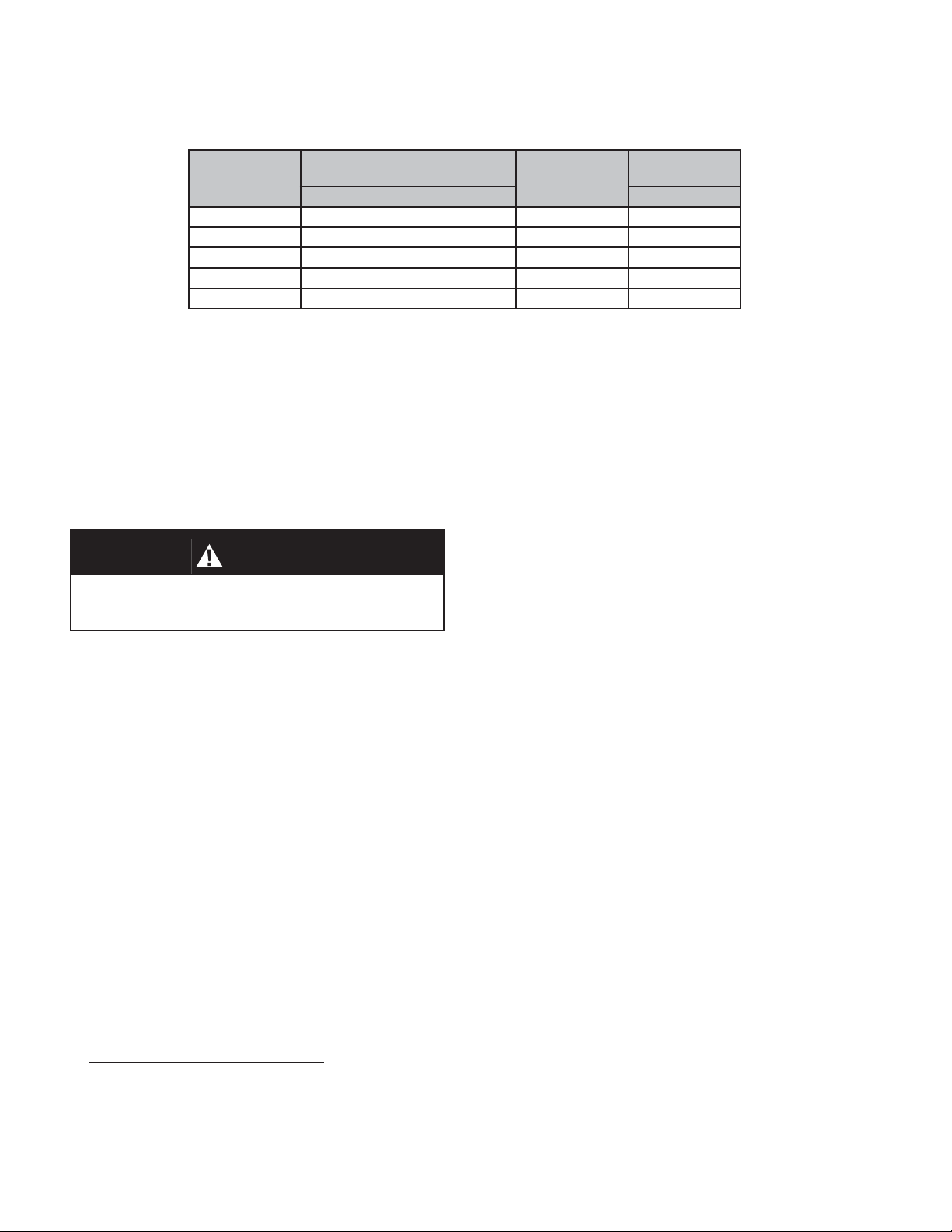
TABLE 1
All Torque Requirements Are Dependant On Gasket Materal
Bolt Torque Specifi cations - ASME #150 Flange Connections
MOUNTING
FLANGE
4” 78 8 5/8” - 11
6” 150 8 3/4” - 10
8” 228 8 3/4” - 10
10” 246 12 7/8” - 9
12” 348 12 7/8” - 9
BOLT TORQUE - ft. * lbs.
FLAT FACE THREAD UNC
NUMBER
BOLTS TOTAL
STUD SPECI-
FICATIONS
All nuts must be torqued in proper sequence and equal increments. Proceed through the tightening sequence until
the recommended torque is attained.
Recheck the torque on each bolt in the same sequence as bolts previously tightened may have relaxed through the
torque sequence.
SECTION IV
IV. MAINTENANCE - Replace Diaphragm
Maintenance procedures hereinafter are based upon removal of the gauge hatch from the tank fl ange.
CAUTION
DO NOT attempt to remove a locked gauge hatch from
a tank or process vessel without fi rst bleeding all pres-
sure from the system.
Hatch with Locking Feature:
Knob Latch: Rotate knob (19) CCW slowly
several revolutions to allow eye bolt (12) and washer
(17) to slide out and dis-engage from the hinge arm
assembly (2).
All Hatches:
Remove cotter pin and washer (35) from arm
pin (9). Slide arm pin (9) out of fl ange base (1).
Lift arm (2) and pallet (30) sub-assembly up to
remove and place on work surface.
Gauge Hatch without Weights: Flip arm/pallet
(2,3) sub-assembly over and secure center bolt (20)
in a vice. Remove the “S” hook (33) from center bolt
(20). Rotate pallet nut (24) CCW and remove nut,
lock washer (23), fl at washer (22) and diaphragm
retainer (5).
Remove diaphragm retainer plate (5) and diaphragm
(4).
Clean and inspect pallet (3) seating surface.
Apply TFE paste around the hole in the pallet (3).
Install new diaphragm (4) in recess of the pallet (3).
Re-install diaphragm retainer plate (5), fl at washer
(22), lock washer (23) and nut (24). Torque nut to
20 ft-lbs.
Re-insert “S” hook (33) into the hole in the center bolt
(20). Use pliers to close the end of the “S” hook and
secure it so it can not be easily removed from the
center bolt (20).
Flip arm/pallet (2,3) sub-assembly over and re-install
the whole pallet (3) /hinge arm assembly (2) on to the
fl ange base assembly (1). Align the pin holes and
insert the pivot pin (9), washer (35) and cotter pin
(15). Turn back the ends of the cotter pin to secure.
Raise and lower arm/pallet (2,3) assembly to confi rm
that diaphragm (4) rest evenly on the seating surface
of the fl ange base (1).
Gauge Hatch with Weights: Flip arm/pallet
(2,3) sub-assembly over and secure center bolt nut
(25) in a vice. Remove the “S” hook (33) from center
bolt (20). Rotate nut (24) CCW to remove nut (24),
lock washer (23) and fl at washer (22).
2
If hatch includes a locking feature, engage eye bolt
(12) and washer (17) over groove in the hinge arm (2)
and secure in place.
Return to Section III for Installation.
IOM-2100
Page 3

SECTION V
V. ORDERING INFORMATION
NEW REPLACEMENT UNIT vs PARTS "KIT" FOR FIELD REPAIR
To obtain a quotation or place an order, please retrieve the Serial Number and Product Code that was stamped
on the metal name plate and attached to the unit. This information can also be found on the Bill of Material
(“BOM”), a parts list that was provided when unit was originally shipped. (Serial Number typically 6 digits).
NEW REPLACEMENT UNIT:
Contact your local Cashco, Inc., Sales Rep re sen ta tive with the Serial Number, Product code and the
pressure setting. With this information they can provide a quotation for a new unit including a complete
description, price and availability.
CAUTION
Do not attempt to alter the original construction of any
unit without assistance and approval from the factory.
All purposed changes will require a new name plate with
appropriate ratings and new product code to accommodate the recommended part(s) changes.
PARTS "KIT" for FIELD REPAIR:
Contact your local Cashco, Inc., Sales Rep re sen ta tive with the Serial Number and Product
code. Identify the parts and the quantity required
to repair the unit from the “BOM” sheet that
was provided when unit was originally shipped.
NOTE: Those part numbers that have a quantity indi-
cated under "Spare Parts" in column "A” refl ect
minimum parts required for inspection and
rebuild, - "Soft Goods Kit". Those in column “B”
include minimum trim replacement parts needed
plus those "Soft Goods" parts from column "A".
If the "BOM" is not available, refer to the crosssectional drawings included in this manual for
part identifi cation and selection.
A Local Sales Representative will provide
quotation for appropriate Kit Number, Price
and Availability.
The contents of this publication are presented for informational purposes only, and while every effort has been made to ensure their accuracy, they are not to be
construed as warranties or guarantees, express or implied, regarding the products or services described herein or their use or applicability. We reserve the right to
modify or improve the designs or specifi cations of such product at any time without notice.
Cashco, Inc. does not assume responsibility for the selection, use or maintenance of any product. Responsibility for proper selection, use and maintenance of any
Cashco, Inc. product remains solely with the purchaser.
IOM-2100
3
Page 4

MODEL 2100
Knob Latch
Center Bolt
No Weights
No Latch
Center Bolt with Weights
PART LIST
ITEM NO. Description ITEM NO. Description ITEM NO. Description
1 Flange 10 Arm Stop 25 Weight Nut
2 Hinge Arm 11 Stop Nut 26 Weight Retainer
3 Pallet 12 Eye Bolt 27 Weight
4
Diaphragm
‡
17 Washer
33 S-Hook
5 Diaphragm Retainer 19 Knob 34 Swivel GrD Washer
6 Pallet Swivel 20 Center Bolt 35 Pivot Grd Washer
7 Latch Stop Pin 22 Flat Washer 36 Name Plate
8 Latch Pivot Pin 23 Lock Washer
9 Arm Pivot Pin 24 Pallet Nut
‡ Recommended replacement parts.
Cashco, Inc.
P.O. Box 6
Ellsworth, KS 67439-0006
PH (785) 472-4461
Fax. # (785) 472-3539
www.cashco.com
email: sales@cashco.com
Printed in U.S.A. 2100-IOM
Cashco GmbH
Handwerkerstrasse 15
15366 Hoppegarten, Germany
PH +49 3342 4243135
Fax. No. +49 3342 4243136
www.cashco.com
email: germany@cashco.com
Cashco do Brasil, Ltda.
Al.Venus, 340
Indaiatuba - Sao Paulo, Brazil
PH +55 11 99677 7177
Fax. No.
www.cashco.com
email: brazil@cashco.com
 Loading...