

Page 1
INSTALLATION, OPERATION & MAINTENANCE MANUAL (IOM)
IOM-1465
12-13
MODEL 1465
PRESSURE REDUCING REGU LA TOR
SECTION I
I. DESCRIPTION AND SCOPE
The Model 1465 is a high pressure reducing reg u la tor designed primarily for analytical sampling and low fl ow ap-
plications. Size is 1/4" (DN8). With proper trim utilization, the unit is suitable for liquid and gaseous ser vice. Refer to
Technical Bulletin 1465-TB for design conditions and se lec tion rec om men da tions. NOT FOR DEAD END SER VICE.
SECTION II
II. INSTALLATION
CAUTION A
Do not dead end (no fl ow demand) down stream of
the regulator. The inlet pres sure will transmit past
the metal seat (not positive shut-off) and equal ize
on the down stream. This will lead to di a phragm
failure, regulator mal func tion, and pos si ble dam age
to sys tem in stru men ta tion down stream.
CAUTION B
For welded installations, all internal trim parts,
seals and diaphragm(s) must be removed from
reg u la tor body prior to welding into pipeline. The
heat of fusion welding will dam age non-metallic
parts if not re moved. NOTE: This does not apply to
units equipped with ex tend ed pipe nip ples.
1. An inlet block valve should always be in stalled.
2. If service application is continuous such that
shut down is not readily accomplished, it is rec om mended that an inlet block valve, outlet block
valve, and a manual bypass valve be in stalled.
3. Pipe unions should be installed to allow re mov al
from piping.
4. An outlet pressure gauge should be located ap prox i mate ly ten pipe diameters down stream, and
within sight.
5. All installations should include a downstream re lief device if the inlet pressure could exceed the
pressure rating of any down stream equip ment or
the max i mum outlet pressure rating of the unit.
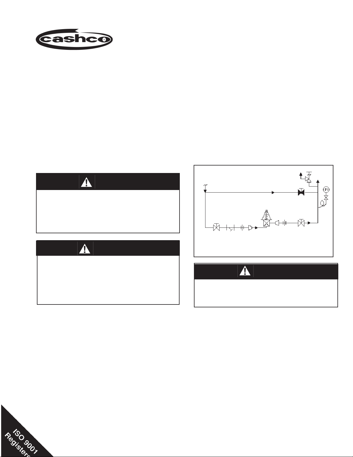
Bypass
Outlet
@ P2
Sup ply
@ P1
SRV
Model 1465
Reducing
Regulator
Recommended Piping Schematic
for Pressure Reducing Station
CAUTION C
Installation of adequate overpressure pro tec tion
is rec om mend ed to pro tect the reg u la tor and all
down stream equip ment from dam age in the event
of reg u la tor failure.
6. Clean the piping of all foreign material in clud ing
chips, welding scale, oil, grease and dirt before
installing the regulator. Strainers are rec om mended.
7. In placing thread sealant on pipe ends prior to
en gage ment, ensure that excess material is
re moved and not allowed to enter the reg u la tor
upon startup.
8. Flow Direction: Install in accordance with the
fl ow di rec tion arrow cast on the body. The inlet
pres sure is con nect ed to the bottom connection
and the outlet (reduced) pressure is connected
to the side connection. When in stall ing, hold by
the body (1) hex to keep the regulator fi rm.
Page 2

9. Basic Regulator - (Refer to Figure 1): Reg u la tor
may be installed in any position in relation to the
pipe. Rec om mend ed position is with spring cham ber vertical upwards. Orient such that the spring
chamber vent hole does not collect rain wa ter or
debris.
10. Regulators are not to be direct buried under ground.
11. For insulated piping systems, recommendation is
to not insulate the regulator.
SECTION III
CAUTION D
DO NOT HYDROSTATIC TEST THRU AN IN STALLED
UNIT; ISOLATE REG U LA TOR FROM TEST. The up per
range spring pres sure level list ed on the name plate
is the rec om mend ed "upper op er a tive limit" for the
sens ing di a phragm (see Sec tion IV. Startup, Num ber
7). High er pres sures could cause inter nal dam age.
In ad di tion, note on the name plate that the Inlet and
Outlet pres sure and tem pera ture ratings are at different lev els.
III. PRINCIPLE OF OPERATION
1. Movement occurs when the inlet pressure pass es
by the seat causing a distributive force on the
un der side of the diaphragm. This, in turn, op poses the point force of the range spring caus ing
up ward movement of the di a phragm, al low ing
IV. START-UP
1. Start with the block valves closed. A bypass valve
may be used to maintain outlet pressure in the
down stream sys tem without changing the fol low ing steps.
2. Relax the range spring (10) by turning the ad just ing
screw (12) counter clockwise (CCW) a min i mum
of three (3) full revolutions. This re duces the outlet
(downstream) pres sure setpoint. NOTE: If the
Option -2 or -22 is utilized, the adjusting screw
(12) and locknut (13) are re placed with a knob
(18) and locknut (13). With Option -2 +80 or -22
+80, the adjusting screw (12) and locknut (13) are
replaced with a handwheel subas sem bly (20) and
locknut (13).
3. If it is a “hot” piping system, and equipped with
a bypass valve, slowly open the bypass valve
to preheat the system piping and to allow slow
ex pan sion of the piping. Ensure proper steam
trap operation if installed. Closely monitor outlet
(down stream) pressure via gauge to ensure not
over-pressurizing. NOTE: If no bypass valve is
in stalled, extra caution should be used in start ing
up a cold system; i.e. do everything slowly.
4. Crack open the outlet (downstream) block
valve.
5. Slowly open inlet (upstream) block valve ob serv ing
the outlet (downstream) pressure gauge. De ter-
the plug to seat. When set pressure de creases,
due to de mand, the dis trib u tive force beneath the
dia phragm lessens - al low ing the range spring to
open the seat and regulate pres sure.
2. A complete diaphragm failure will cause the reg u la tor to fail open.
SEC TION IV
mine if the regulator is fl owing. If not, slowly rotate
the regulator adjusting screw (12) clock wise (CW)
until fl ow begins.
6. Continue to slowly open the inlet (upstream) block
valve until fully open.
7. Continue to slowly open the outlet (downstream)
block valve, especially when the downstream pip ing
system isn’t pressurized. If the outlet (down stream)
pressure exceeds the desired pres sure, close the
block valve and go to Step 2, then return to Step
4.
8. When fl ow is established steady enough that the
outlet (downstream) block valve is fully open, begin
to slowly close the bypass valve if installed.
9. Develop system fl ow to a level near its expected
normal rate, and reset the regulator setpoint by
turning the ad just ing screw (12) CW to increase
outlet pressure or CCW to reduce outlet pressure.
10. Reduce system fl ow to a minimum level - ob serve
setpoint. Outlet pressure will rise from the setpoint
of Step 9. The maximum rise in outlet pressure
on decreasing fl ow should not exceed the stated
upper limit of the range spring (10) by greater than
10%; i.e. 5-30 psig (.34-2.1 Barg) range spring, at
low fl ow the outlet pressure should not exceed 33
psig (2.3 Barg). If it does, consult factory.
2
IOM-1465
Page 3

SECTION V
V. SHUTDOWN
1. On systems with a bypass valve, and where sys tem pressure is to be maintained as the regu la tor
is shut down, slowly open the bypass valve while
closing the inlet (up stream) block valve. Fully
close the inlet (upstream) block valve. (When on
bypass, the system pressure must be con stantly
observed and manually reg u lat ed. ) Close the
outlet (down stream) block valve.
SECTION VI
VI. MAINTENANCE
WARNING 1
SYSTEM UNDER PRESSURE. Prior to per form ing any
main te nance, isolate the reg u la tor from the sys tem
and relieve all pres sure. Failure to do so could result
in personal injury.
A. General:
1. Maintenance procedures hereinafter are
based upon re mov al of the regulator from
the pipe line where in stalled.
2. Owner should refer to owner’s procedures for
removal, handling, cleaning and dis posal of
non-reusable parts, i.e. O-rings, etc.
CAUTION E
Do not leave a bypassed reg u la tor unattended.
2. If the regulator and system are to both be shut down, slowly close the inlet (upstream) block
valve. Close the outlet (downstream) valve only
if reg u la tor re mov al is required.
units with Option -80 (spring ranges 270-400
psig (18.6-27.6 Barg) and 360-500 psig (24.8
-34.5 Barg)) also remove the thrust bearing
(15), upper bear ing washer (16), and lower
bearing wash er (17). Inspect threads of spring
chamber (2) for cleanliness.
5. Remove pressure plate (9) and inspect to
ensure no deformation due to over-pres suri za tion. If deformed, replace.
6. Remove diaphragm(s) (8), O-ring (7) and
push er plate (6). Inspect pusher plate (6) to
ensure no deformation due to over-pres suri za tion. If de formed, re place. Dis card O-ring
(7) and diaphragm(s) (8).
3. Refer to Figure 1 for the standard regu la tor
and its options.
B. Diaphragm Replacement:
1. Securely install the body (1) in a vise with the
spring chamber (2) directed up wards.
WARNING 2
SPRING UNDER COM PRES SION. Prior to re mov ing
spring chamber, relieve spring com pres sion by back ing out the ad just ing screw or handwheel. Failure
to do so may result in fl ying parts that could cause
per sonal in ju ry.
2. Relax range spring (10) by turning ad just ing
screw (12) CCW until removed from spring
cham ber (2). NOTE: If the Option -2 or -22 is
utilized, the adjusting screw (12) and locknut
(13) are replaced with a knob (18) and locknut
(13). With the Option -2 +80 or -22 + 80, the
ad just ing screw (12) and lock nut (13) are
replaced with a handwheel subas sem bly (20)
and lock nut (13).
3. Loosen spring chamber (2) by placing wrench
on “fl ats” and rotating CCW. DO NOT use the
fl ats on either side of the vent hole.
4. Remove spring chamber (2), spring button
(11), and range spring (10). NOTE: For
IOM-1465
7. Clean body (1) and body recess according
to owner's procedures. NOTE: On regulators
orig i nal ly sup plied as “oxygen clean”, Option
1465-55, main te nance must include a lev el of
clean li ness equal to Cash co’s clean ing Stan dard #S-1134. Con tact factory for details.
8. Install new O-ring (7) and diaphragm(s) (8).
NOTE: Refer to the quantity of diaphragm(s)
(8) in cor po rat ed in the bill of materials list ing.
De pend ing on outlet pressure level, multiple
metal di a phragms may be “stacked”.
9. Visually center pressure plate (9) on
diaphragm(s) (8). Place the range spring (10)
on to the retainer hub of the pressure plate
(9).
10. Place multi-purpose, high temperature grease
into the depression of the spring button (11)
where adjusting screw (12) bears. Set spring
button (11) onto range spring (10); ensure
spring button (11) is laying fl at. NOTE: For
units with Option -80 (spring ranges 270-400
psig (18.6-27.6 Barg) and 360-500 psig (24.8-
34.5 Barg) position spring button (11), thrust
bear ing (15), upper bearing washer (16), and
lower bearing wash er (17) on top of the range
spring (10).
3
Page 4

11. Apply an appropriate lubricant to the threads
of the spring chamber (2). Reverse Steps
B.2 and B.3 to complete assembly. Tighten
spring cham ber (2) to body (1) with a 30-35
Ft-lbs torque value.
pro ce dures. NOTE: On reg u la tors originally
sup plied as "oxygen clean", Op tion 1465-55
main te nance must in clude a level of clean li ness equal to Cashco's clean ing spec. #S-
1134. Contact factory for details.
12. Pressurize with air and spray with liquid leak
detector to test around body (1) and spring
cham ber (2) for leak age. En sure that an outlet
pressure is main tained dur ing this leak test of
at least mid-range spring level; i.e. 125-200
psig (8.6-13.8 Barg) range spring, 163 psig
(11.2 Barg) test pres sure min i mum.
C. Trim Inspection:
1. Trim inspection requires that the diaphragm(s)
be re moved. Refer to pre vi ous procedure
Sec tion VI.B, steps 1 through 7.
2. Remove body (1) from vise and secure a
screwdriver, tool end up, in vise. Set body (1)
so as to engage screwdriver into slotted end of
the plug (3) from the body (1) inlet con nec tion
and hold fi rm.
3. Remove pusher plate (6). Looking down into
the body (1) cavity, use a slotted tool to push
down on the spring seat (5) and slip sideways
to dis en gage (through slot) from plug (3).
4. Remove spring seat (5) and plug spring (4).
5. Grasp plug (3) while carefully lifting body (1).
Remove plug (3) from body (1) inlet, taking
care not to allow plug (3) to drop out.
6. Inspect integral seat in body (1). If seat shows
erosion or wear, re place regulator.
7. Clean debris from within body (1) cavity.
Clean parts to be reused according to owner's
8. Inspect spring seat (5), plug spring (4) and
plug (3). If worn, nicked or depressed, re place
regulator.
9. Lap plug (3) with lapping compound by in sert ing it back up into the body (1) inlet and
hold fi rm. Engage a screwdriver into the slotted
end of the plug (3) from the body (1) inlet and
rotate plug (1) back and forth in a circular motion. Do not overlap. Clean lapping com pound
on plug (3) and in body (1).
10. Reverse steps 1 through 5 for reassembly.
NOTE: When reassembling plug (3), plug
spring (4), and spring seat (5), be sure that
this "assembly" is centered into the body (1)
cav i ty to ensure proper seating of plug (3).
Apply an appropriate lubricant to the threads
of the spring chamber (2). Tighten spring
cham ber (2) to body (1) with a 30-35 Ft-lbs
torque value.
11. Bench test unit for suitable operation. NOTE:
Reg u la tors are not tight shut off devices.
Even if pres sure builds up beyond setpoint,
a reg u la tor may or may not de vel op bubble
tight shut off.
12. Pressurize with air and spray with liquid leak
detector to test around body (1) and spring
cham ber (2) for leakage. Ensure that an outlet
pressure is main tained during this leak test of
at least mid-range spring level; i.e. 125-200
psig (8.6-13.8 Barg) range spring, 163 psig
(11.2 Barg) test pres sure minimum.
SECTION VII
VII. TROUBLE SHOOTING GUIDE
1. Erratic operation; chattering.
Possible Causes Remedies
A. Oversized regulator; inadequate
rangeability.
B. Cavitation B. Use multiple 1465's in series to stage the pressure drops. Refer
4
A1. Check actual fl ow conditions, re-size regulator for minimum and
maximum fl ow.
A2. Increase fl ow rate.
A3. Decrease regulator pressure drop; decrease inlet pressure by
placng a throttling orifi ce in inlet piping union.
A4. Install next step higher range spring. Contact factory.
A5. Before replacing regulator, contact factory.
to 1465 Technical Bulletin for water cavitation chart.
IOM-1465
Page 5

2. Leakage through the spring chamber vent hole.
Possible Causes Remedies
A. Normal-life diaphragm failure. A. Replace diaphragm
B1. Can be caused by excessive chattering. See No. 1 to remedy
chatter.
B2. Can be caused by corrosive action. Consider alternate diaphragm
B. Abnormal short-life diaphragm
failure.
3. Regulator can't pass suffi cient fl ow.
Possible Causes Remedies
A. Regulator undersized.
B. Plugged trim.
C. Incorrect range spring(screwing in
CW of adjsting screw
does not allow bringing pressure
level up to proper level).
D. Too much droop
E. Cavitation
4. Excessive pressure downstream.
Possible Causes Remedies
A. Regulator not closing tightly.
B. Downstream block.
C. No pressure relief protection. C. Install safety relief valve or rupture disc.
D. Restricted diaphragm movement.
material.
B3. For composition diaphragms, ensure not subjecting to over-
temperature conditions.
B4. Downstream (outlet) pressure buildup occurring that overstresses
diaphragms. Relocate regulator or protect with safety relief valve.
A1. Confi rm by opening bypass valve together with regulator.
A2. Check actual fl ow conditions, re-size regulator; if regulator
has inadequate capacity, replace with larger unit.
B. Remove regulator from line and check for debris in inlet
connection.
C. Replace range spring with proper higher range. Contact factory.
D1. Review droop expected.
D2. Contact factory.
E. Use multiple 1465's in series to stage the pressure drops. Refer
to 1465 Technical Bulletin for water cavitation chart.
A. Inspect the seating. Check tht plug (3), plug spring (4), and spring
seat (5) are centered in body (1) cavity. Replace regulator should
these steps not remedy.
B. Check system; isolate (block) fl ow at regulator inlet - not outlet.
Relocate regulator if necessary.
D. Ensure no moisture in spring chamber at temperatures below
freeze point. Ensure no dust or debris entering vent opening. If
rainwater or debris enter, re-orient regulator.
5. Sluggish operation.
Possible Causes Remedies
A. Fluid too viscous. A. Heat fl uid. Contact factory
6. Excessive seat leakage.
Possible Causes Remedies
A. Foreign matter on seating surface,
erosion of seating surface.
B. Cavitation
7. Leakage out of threaded connection between body and spring chamber.
Possible Causes Remedies
A. Insuffi cient spring chamber torque. A. Tighten spring chamber on body using suffi cient torque.
B. Damaged o-ring B. Replace o-ring.
IOM-1465
A. Inspect and clean seat. If seat eroded, replace regulator.
B. Use multiple 1465's in series to stage pressure drops. Refer to
1465 Technical Bulletin for water cavitation chart.
5
Page 6

SECTION VIII
VIII. ORDERING INFORMATION
NEW REPLACEMENT UNIT vs PARTS "KIT" FOR FIELD REPAIR
To obtain a quotation or place an order, please retrieve the Serial Number and Product Code that was stamped
on the metal name plate and attached to the unit. This information can also be found on the Bill of Material
("BOM"), a parts list that was provided when unit was originally shipped. (Serial Number typically 6 digits).
Product Code typical format as follows: (last digit is alpha character that refl ects revision level for the product).
–
NEW REPLACEMENT UNIT:
Contact your local Cashco, Inc., Sales Rep re sen ta tive with the Serial Number and Product code.
With this information they can provide a quotation
for a new unit including a complete description,
price and availability.
CAUTION
Do not attempt to alter the original construction
of any unit without assistance and approval from
the factory. All purposed changes will require a
new name plate with appropriate ratings and new
product code to accommodate the recommended
part(s) changes.
PARTS "KIT" for FIELD REPAIR:
Contact your local Cashco, Inc., Sales Rep re sen ta tive with the Serial Number and Product code.
Identify the parts and the quantity required to repair
the unit from the "BOM" sheet that was provided
when unit was originally shipped.
–
7
NOTE: Those part numbers that have a quantity indicated
under "Spare Parts" in column "A” refl ect minimum
parts required for inspection and rebuild, - "Soft
Goods Kit". Those in column “B” include minimum
trim replacement parts needed plus those "Soft
Goods" parts from column "A".
If the "BOM" is not available, refer to the crosssectional drawings included in this manual for part
identifi cation and selection.
A Local Sales Representative will provide quotation
for appropriate Kit Number, Price and Availability.
The contents of this publication are presented for informational purposes only, and while every effort has been made to ensure their accuracy, they are not to be
construed as warranties or guarantees, express or implied, regarding the products or services described herein or their use or applicability. We reserve the right to
modify or improve the designs or specifi cations of such product at any time without notice.
Cashco, Inc. does not assume responsibility for the selection, use or maintenance of any product. Responsibility for proper selection, use and maintenance of any
Cashco, Inc. product remains solely with the purchaser.
6
IOM-1465
Page 7

13
14
12
22
11
2
16
15
10
8
5
4
3
Figure 1: Basic Model 1465
18
13
19
Option -22 Panel Mounting (hand-
wheel portion is same for Option -2
Handwheel)
12
2
17
9
7
Option -80, High Pressure
6
Spring Chamber Construction
1
Item Number Description
1 Body Subassembly
2 Spring Chamber
3 Plug
4 Spring
5 Spring Seat
6 Pusher Plate
7 O-ring
8 Diaphragm
9 Pressure Plate
10 Range Spring
11 Spring Button
12 Adjusting Screw
13 Adjusting Screw Lock Nut
14 Name Plate
15 Thrust Bearing
16 Upper Bearing Washer
17 Lower Bearing Washer
2
18 Knob
19 Mounting Nut
ITEM NUMBERS NOT SHOWN
20 Handwheel Subassembly
21 Pin
IOM-1465
7
Page 8

Cashco, Inc.
P.O. Box 6
Ellsworth, KS 67439-0006
PH (785) 472-4461
Fax. # (785) 472-3539
www.cashco.com
email: sales@cashco.com
Printed in U.S.A. IOM-1465
Cashco GmbH
Handwerkerstrasse 15
15366 Hoppegarten, Germany
PH +49 3342 4243135
Fax. No. +49 3342 4243136
www.cashco.com
Email: germany@cashco.com
Cashco do Brasil, Ltda.
Al.Venus, 340
Indaiatuba - Sao Paulo, Brazil
PH +55 11 99677 7177
Fax. No.
www.cashco.com
Email: brazil@cashco.com
 Loading...