

Page 1
INSTALLATION, OPERATION & MAIN TE NANCE MANUAL (IOM)
IOM-123 1+6+S
MODEL 123-1+6+S DIFFERENTIAL
BACK PRESSURE / RELIEF REGULATOR
SECTION I
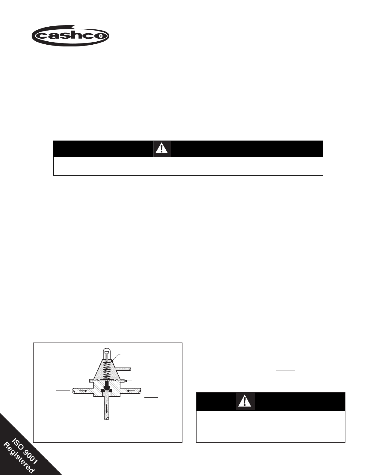
I. DESCRIPTION AND SCOPE
The Model 123-1+6+S Differential is designed for high pressure liquid or gas applications to Cashco drawing nos.
32934 (NACE construction) and 32935 (Non-NACE construction). It is used to control differential upstream (inlet or
P
) pressure and a loading (P
1
25, and 40).
This is not a safety device and must not be sub sti tut ed for a code approved pres sure safety
relief valve or rupture disc. NOT FOR STEAM SERVICE. NOT FOR OXYGEN SERVICE.
II. INSTALLATION
This unit was designed and is used almost exclusively on compressor and turbo expander seal systems. REFER
TO COM PRES SOR/EXPANDER MANUFACTURER'S MANUAL FOR DE TAILED INSTALLATION, START-UP
AND SHUTDOWN OF THIS UNIT. Install regulator with Inlet (P
in accordance with the directional fl ow arrow cast on body (1).
) pressure to a rotating shaft seal. Sizes are 1/2", 3/4", 1", and 1-1/2" (DN15, 20,
Load
CAUTION A
SECTION II
) pressure coming in the side body (1) connection
1
DIFF
12-13
IIl. PRINCIPLE OF OPERATION
1. Movement occurs as pressure variations reg is ter
on the diaphragm (3). The registering pressure is
the inlet (P
on the "un der neath" side of the diaphragm (3).
The second pressure registered is the loading
(P
LOAD
the diaphragm (3). The range spring (18) determines the differential pres sure setpoint (P
∆ P
= P1 - P
SIZING
P1 > P
LOAD
P1 = P
∆ P
+ P
LOAD
DIFFERENTIAL
= P1 - P
INLET
@ P
Model 123-1+6+S Differential Schematic
) or upstream pressure which reg is ters
1
) pressure in the spring chamber (2) "above"
2
SET
LOAD
1
OUTLET @ P
RANGE SPRING:
SETTING @ P
LOADING FLUID
@ P
DIA PHRAGM
2
SET
LOAD
(Optional)
INLET
@ P
1
SECTION III
). As
SET
inlet (P1) pressure drops, the range spring (18)
pushes the diaphragm (3) down, clos ing the port;
as inlet (P1) pressure increases, the diaphragm
(3) pushes up and the port opens. As the loading (P
tends to follow. An increase in (P
) pressure varies, the inlet (P1) pressure
LOAD
) will increase
LOAD
inlet (P1) pressure by nearly an equal amount ;
a decrease in (P
will decrease the inlet (P1)
LOAD)
pres sure.
2. A complete diaphragm (3) failure will cause the
fl uids to mix in the spring chamber (2) or loading
pressure piping. Reg u la tor action will "fail close"
under a di a phragm (3) failure.
3. Under normal operating conditions, the inlet (P
pressure should be greater than the loading
(P
) pressure by the range spring (P
LOAD
SET
) set-
point.
CAUTION B
Limit any fi eld hydrostatic test to 1-1/2 times the
Maximum Pressure Rat ing (See Ta ble 1). En sure
that the test pressure is applied uniformly to the
body inlet, body outlet, and spring chamber.
)
1
Page 2
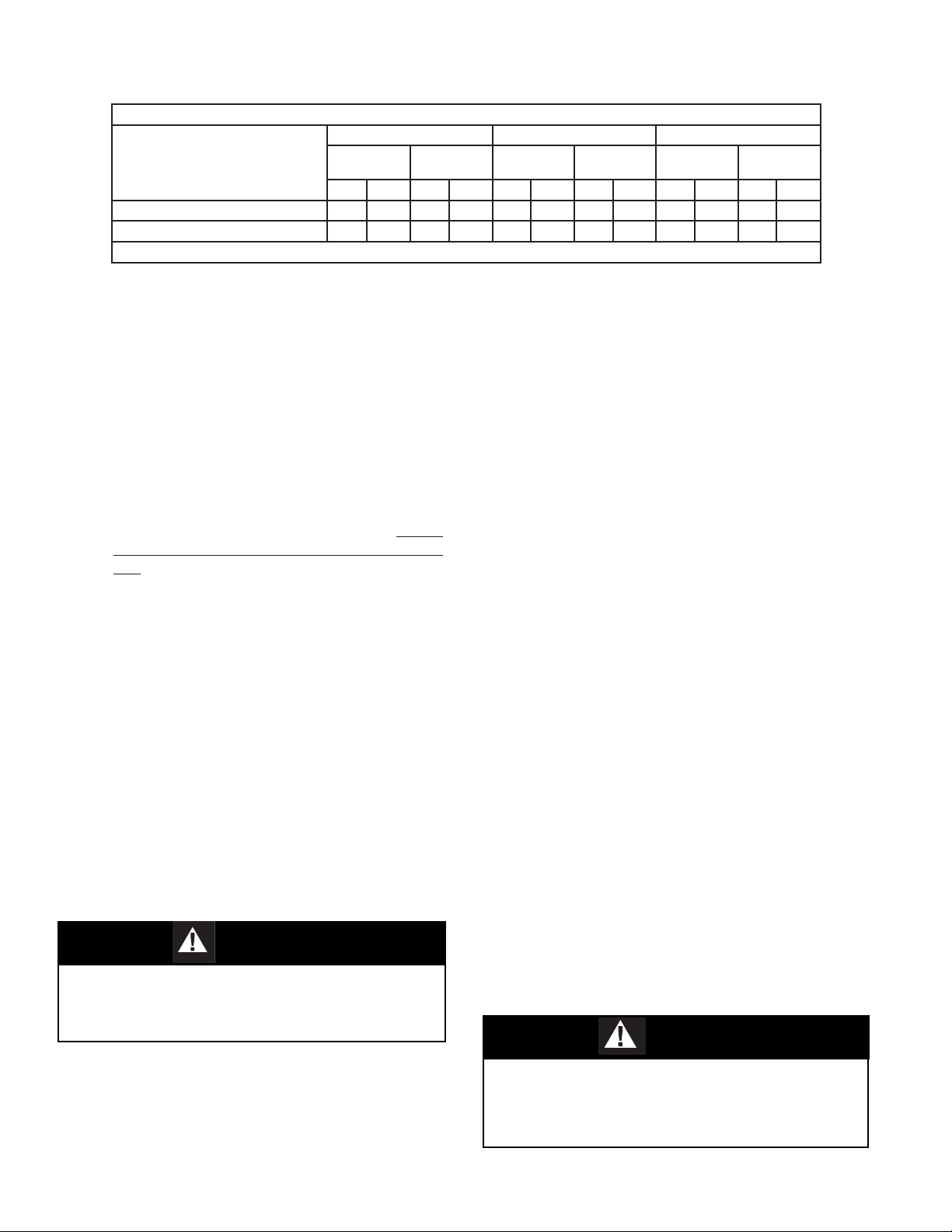
TABLE 1
MAX OPERATING PRESSURES & TEMPERATURE RATING SPECIFICATIONS
NPT and 1500# ANSI Flg. 600# ANSI Flg. 900# ANSI Flg.
DESCRIPTION
Max. Pressure for CS Body/Spg. Ch, 1500 (103) 1500 (103) 1480 (102) 1270 (88) 1500 (103) 1500 (103)
Max. Pressure for SST Body/Spg. Ch. 1500 (103) 1500 (103) 1440 (99) 995 (69) 1500 (103) 1500 (103)
Operating Temperature Range -20°F (-28°C) to +400F (+204C)
100°F
(38°C)
psig (Barg) psig (Barg) psig (Barg) psig (Barg) psig (Barg) psig (Barg)
400°F
(205°C)
100°F
(38°C)
400°F
(205°C)
100°F
(38°C)
400°F
(205°C)
SECTION IV
IV. STARTUP
REFER TO THE COMPRESSOR/EXPANDER MANUFACTURER'S MANUAL FOR DETAILED STARTUP OF
THIS UNIT.
1. On initial start-up with your system op er at ing at
nor mal conditions, check the differential gauge to
ensure the desired differential pressure is being
maintained. If not, go to step 2 and make one fi nal
ad just ment. (This should only be nec es sary on
fi rst start-up.) NOTE: It is crucial that the adjust-
ing screw (17) threads not be dam aged. Do not
use pliers or locking pliers on the adjusting screw
(17).
3-4 complete revolutions. Loosen lock nut (9)
by turning CCW until it is tight (dou ble-nutted)
against closing cap (22). Now the differential
set ting may be adjusted by turning the closing
cap (22) CW to increase differential or CCW
to de crease. After desired setting is reached,
loos en lock nut (9) from clos ing cap (22) and
tighten each se cure ly to spring chamber (2).
b. Remove closing cap (22) from ad just ing screw
2. To adjust differential setting, use one of these two
methods:
(17) by turning CCW. Loosen lock nut (9) by
turning CCW. Turn the adjusting screw (17)
CW to in crease differential pressure or CCW
a. Loosen the closing cap (22) by turning CCW
to de crease. Tight en lock nut (9) and replace
clos ing cap (22).
SECTION V
V. SHUTDOWN
REFER TO THE COM PRES SOR/EXPANDER MAN U FAC TUR ER'S MANUAL FOR DETAILED SHUTDOWN OF
THIS UNIT.
SECTION VI
VI. MAINTENANCE
WARNING 1
SYSTEM UN DER PRES SURE. Prior to performing any
maintenance, isolate the reg u la tor from the system and
relieve all pressure(s). Failure to do so could result in
personal injury.
A. General:
1. Maintenance procedures hereinafter are
based upon removal of the regulator unit from
the pipe line where installed.
2
2. Owner should refer to owner's procedures for
re mov al, handling, cleaning and disposal of
non re us able parts, i.e. gaskets, etc.
3. Refer to Figure 5 for differential regulator
cutaway drawing.
WARNING 2
SPRING UNDER COMPRESSION. Prior to re mov ing
spring chamber subassembly (2), relieve range spring
(18) com pres sion by back ing out the ad just ing screw
(17). Fail ure to do so may result in fl ying parts that
could cause per son al injury.
IOM-123-1+6 +S DIFF
Page 3
CAUTION C
DO NOT AT TEMPT TO REMOVE ADJUSTING SCREW
(6) FROM TOP OF SPRING CHAM BER (2). The ad just ing screw (6) is threaded up from inside the spring
chamber (2) and the CCW rotation used to relieve
range spring (14) tension will come to a stop. At the
stop ping point, do not apply any torque to ad just ing
screw (6) or dam age may occur and ren der the unit
in op er a ble. See Figure 1.
B. Disassembly:
9
17
2
28
29
2
9
17
28
29
1. Securely install the body (1) in a vise with the
spring chamber (2) directed upwards.
2. Remove closing cap (22).
3. Loosen sealing locknut (9) by rotating CCW.
Relax range spring (18) by turning adjusting
screw (17) CCW.
4. Draw or em bed a match mark be tween body
(1) casting and spring chamber (2) sub as sem bly along fl anged area.
5. Re move all body flange hardware
(7,8,30,41,42).
6. Re move spring chamber (2) and connected
parts, range spring (18) and spring but ton
(19).
CAUTION D
When body fl ange hardware (7,8,30,41,42) is re moved
from this unit it should al ways be re placed with new.
The new hardware (7,8,30,41,42) must have the prop er
grade spec i fi ca tion iden ti fi ca tion mark ings and meet
the following stan dards:
1. All cap screws (7,30) and fl ange stud nuts (8)
must have "heavy hex heads".
2. All studs (41,42) and cap screws (7,30) must
comply with or exceed the requirements of
ASTM-A-193, Grade B7.
3. All fl ange stud nuts (8) must comply with
or exceed the requirements of ASTM A-194,
Grade 2H.
New body fl ange hardware (7,8,30,41,42) may be pur-
chased from Cashco, Inc. or through the OEM.
7. Adjusting screw (17) o-ring inspection:
a. With locknut (9) and closing cap (22) re-
moved, turn adjusting screw (17) CW as
far as possible by grasping the fl ats on
top end. Care ful ly reach in side spring
cham ber (2) and grasp ad just ing screw
(17) by hand. Remove ad just ing screw
(17) by rotating CCW. See Fig ure 1A.
A. Removal
Figure 1: Adjusting screw (17) o-ring inspection.
B. Reassembly
b. Inspect the backup ring (28) and quad ring
(29) for wear. If nicked or torn - replace.
NOTE: Make certain the tefl on backup
ring (28) will insert into spring cham ber (2)
fi rst, before the quad ring (29). (See Fig ure 7 blow-up illustration). Make sure the
quad ring (29) is on straight with no twist.
Use a good grade light weight grease on
the ring seals (28,29).
c. Lubricate adjusting screw (17) threads.
Carefully re in stall adjusting screw (17) up
into the spring cham ber (2) by ro tat ing
adjusting screw (17) CW until top of
ad just ing screw (17) protrudes from top
of spring chamber (2) (See Fig ure 1B.).
NOTE: Care should be taken when hold ing and ro tat ing adjusting screw (6) so the
quad ring (29) and back up ring (28) are
not in ad vert ent ly nicked or torn. Grasp
top of ad just ing screw (17) and turn CCW
until rotation stops (see CAUTION C).
d. Loosely install the lock nut (9) and closing
cap (22).
8. Lift up and remove the diaphragm sub as sem bly con sist ing of the pis ton (14), piston
nut (6), di a phragm (3), di a phragm cov ers (24)
(NACE unit only, Cashco Dwg. 32934), pres sure plate (20), pusher plate (21), seal ing
washer (27), pres sure plate o-ring (31) and
pusher plate o-ring (34). Re move the fl ange
o-ring (32).
9. Loosen piston nut (6) and separate all parts
(3,24 (NACE units only),14,20,21,27,31,34)
of the diaphragm (3) sub as sem bly.
IOM-123-1+6 +S DIFF
3
Page 4

10. Inspect pressure plate (20) and pusher plate
(21) to assure no de for ma tion due to overpres sur iza tion. Inspect diaphragm (3). If
de formed, replace.
11. Remove cylinder subassembly (12) by ro tat ing CCW. NOTE: For 1-1/2" (DN40) body
reduced orifi ce only, also remove the cylinder
bush ing (33) at this time. See Figure 6.
12. Inspect cylinder seat (12.2). If seat shows
ero sion or wear, the entire cylinder/seat as sem bly (12) must be re placed.
6. Place pusher plate o-ring (34) into recess of
pusher plate (21). Lubricrate with good grade
lightweight grease.
7. Place diaphragm (3) and diaphragm cov ers
(24) (NACE construction only) according to
fol low ing instructions:
a. NACE variation only (Cashco Dwg.
#32934): Place one of the two di a phragm
cover(s) (24) over piston (14) post. Place
diaphragm (3) and sec ond di a phragm
cov er (24) over piston (14) post.
13. Remove body (1) from vise.
14. Clean all parts to be reused according to
owner's procedures. Use special care clean ing the fl at mating sur fac es of the body
(1), cyl in der (12) and cylinder bushing (33)
shoul ders (1-1/2" (DN40) size only) as these
pres sur ized joints are metal-to-metal.
C. Reassembly:
1. Place body (1) back into vise.
2. a. For standard orifi ce: Lu bri cate the
cyl in der (12) threads light ly with thread
seal ant, insert the cyl in der (12) into the
body (1) and screw CW until fi nger tight.
Im pact the cyl in der (12) into the body
(1).
b. For 1-1/2" (DN40) body reduced or i fi ce
ONLY: Lu bri cate cylinder (12) and cyl in der bush ing (33) threads lightly with
thread seal ant. Screw the cylinder (12)
into the cylinder bushing (33) until fi nger
tight. Then screw the cylinder (12) and
cylinder bushing (33) "sub as sem bly" into
the body (1) until fi nger tight. Impact this
cylinder (12)/cyl in der bushing (33) "as sem bly" into the body (1). See Figure
6.
3. Place diaphragm
(1) fl ange.
4. Place piston (14) in a vise with threaded post
portion directed upwards, grasping on the
hex ag o nal surface.
5. Position properly oriented pusher plate (21)
over piston (14) post.
fl ange o-ring (32) on body
b. NON-NACE variation only (Cashco
Dwg. #32935): Place diaphragm (3)
over piston (14) post.
8. Place pressure plate o-ring (31) into recess
of pressure plate (20). Lubricrate with a good
grade lightweight grease. Position pressure
plate (20) over the piston (14) post.
9. Place the sealing wash er (27) (metal side up)
over the piston (14) post.
10. Thread piston nut (6) onto piston (14) post.
Torque to the following value:
All sizes: 45-50 Ft-lbs (61-68 N-m).
11. Release the piston (14) from vise. Insert the
piston/diaphragm subassembly into the body
(1) with piston (14) engaging the cylinder (12).
Align diaphragm (3) and body (1) bolt holes.
12. Place the range spring (18) onto the retainer
hub of the pressure plate (20).
13. Place multipurpose, high temperature grease
into de pres sion of spring button (19) where
ad just ing screw (17) bears. Set spring button
(19) onto range spring (18); ensure spring
button (19) is laying fl at.
14. Aligning matchmarks, place spring cham ber
(2) over the stacked parts. Rotate adjusting
screw (17) CW into spring cham ber (2) until
contact is made with the spring button (19).
NOTE: Contact will begin to lift the spring
chamber (2) up from body (1). Relax ad just ment screw (17) so that spring cham ber
(2) and body (1) just make contact. (This will
keep the range spring (18) from falling over
while the body (1) and spring chamber (2) are
bolted back to geth er).
4
IOM-123-1+6 +S DIFF
Page 5

15. Using "NEW" studs (41,42) and nuts (8) (see
CAUTION D), thread one nut (8) onto each
stud (41,42) ap prox i mate ly 1.25" (32 mm).
Drop the studs (41,42) with nuts (8) through
holes in spring chamber (2). (This will assist
in keep ing the spring chamber (2) cen tered on
valve body (1) and prevent parts from moving
dur ing reassembly).
Using "match marks" made in Step B.4 as a
guide, replace spring chamber (2) onto body
(1). Thread lower nuts (8) onto studs (41,42)
and tight en by hand. Adjust length of studs
(41,42) by using the top nut (8) to allow at
least 3-4 threads protruding from the lower
nut (8).
Torque body fl ange hardware (7,8,30,41,42)
using small increments in a 180° alternating
pattern until fl ange mating sur fac es of body
(1) and spring cham ber (2) are metal to metal.
This creates a "fi xed com pres sion" on the
di a phragm (12) and o-ring seal (32). Rec om mend ed torque val ues are listed in Table 2.
TABLE 2
BODY SIZE
in
1/2" - 1-1/2"
(DN)
(15-40)
ITEM
NO.
7, 8, 30,
41, 42
THREAD
SIZE
7/16-20 32-36 (43-49)
TORQUE VALUE
Ft-lbs (N-m)
D. Bench test for suitable operation (Test Fluid:
Air or compressed gas).
1. Check for desired differential spring set ting
and regulator performance (with no loading
pressure):
a. Close No. 1, No. 2, and No. 4 shut-off
valves. Open No. 3 and No. 5 shut-off
valves.
Inlet P
Pressure
No. 2
Shut-off
Pressure
Gauge
Valve
No. 5 Isolation Valve
No. 4
Shut-off
Valve
Outlet P
Pressure
No. 1
Shut-off
Valve
1
Figure 2: Recommended Bench Test
Piping Schematic for 123-1+6+S
fer en tial setting, check seat leak age at
40% below 15 psig (1.0 Barg); or 9 psig
(.62 Barg). Seat leak age should be min i mal (less than 20 SCFH). See SEC TION
VII-5. TROU BLE SHOOT ING GUIDE if
seat leakage is excessive.
2. Proof test to check for ex ter nal leakage.
a. Close No. 1, No. 3, and No. 5 shut-off
valves. Open No. 2 and No. 4 shut-off
valves. Build inlet pressure to No. 1 shutoff valve to 1-1/2 times maximum inlet
pressure, but not to exceed 1-1/2 times
Maximum Pres sure Rating (See Table
1).
b. Crack open No.1 shut-off valve and allow
a pressure buildup simultaneously in the
body (1) and spring chamber (2). Spray
the entire regulator with a liquid leak
de tec tor and visually inspect for external
leakage. Repair unit if leak is detected.
See SECTION VI MAINTENANCE.
No. 3
Shut-off
Valve
2
b. Apply inlet (P
valve (10-15 psig (.69-1.0 Barg) above
desired differential spring setting). Crack
open No. 1 shut-off valve and check for
valve opening at desired differential set ting. Refer to SECTION IV-2. if range
spring (18) adjustment is required.
c. Check for performance. NOTE: A metal
seat will experience a slight seat leak age). Seat leakage should be quantifi ed
at 40% deviation from setpoint. For
ex am ple: For a 15 psid (1.0 Bard) dif-
IOM-123-1+6 +S DIFF
) pressure to No. 1 shut-off
1
c. Shut off line pressure to No. 1 shut-off
valve. Open No. 3 shut-off valve to re lieve all pressure from the test valve and
all shut-off valves.
3. Return to Section II for Installation and Sec tion IV for Startup.
5
Page 6

VII. TROUBLE SHOOTING GUIDE
1. Erratic Operation; chattering
Possible Causes Remedies
A. Oversized regulator. A1. Check actual fl ow conditions, resize regulator for minimum and
B. Inadequate rangeability. B1. Increase fl ow rate.
C. Worn piston/cylinder; inadequate guiding. C. Replace trim.
D. Unstable loading pressure. D1. Stabilize loading pressure; i.e. pump, control, valve, etc.
2. Regulator inlet (upstream) pressure too high.
Possible Causes Remedies
A. Regulator undersized. A1. Confi rm by opening bypass valve together with regulator.
B. Plugged inlet strainer. B. Remove strainer screen and clean; consider leaving screen out.
C. Plugged trim. C. Remove trim and check for plugged holes in cylinder.
D. Incorrect range spring (screwing out CCW of
adjusting screw does not allow bringing
pressure level to a stable and proper level).
E. Too much propotional band (rise). E1. Review Proportional Band (rise) expected.
F. Restricted diaphragm movement. F1. Ensure no moisture in spring chamber at temperatures below
G. Diaphragm failure. G. Replace diaphragm.
SECTION VII
maximum fl ow.
A2. Increase fl ow rate.
A3. Install next step higher range spring. Contact factory.
A4. Before replacing regulator, contact factory.
B2. Decrease regulator pressure drop.
B3. Install next step higher range spring. Contact factory.
D2. Air in loading piping in liquid service. Vent as fully as possible.
A2. Check actual fl ow conditions, resize regulator; if regulator has
inadequate capacity, replace with larger unit.
D. Replace range spring with proper lower range. Contact factory.
E2. Contact factory.
freezing.
F2. Ensure no dust or debris entering vent opening. If rainwater or
debris can enter, re-orient spring chamber.
3. Main valve fl uid in loading fl uid piping.
Possible Causes Remedies
A. Normal-life diaphragm failure. A. Replace diaphragm.
B. Abnormal short-life diaphragm failure. B1. Can be caused by excessive chattering. See No. 1 to remedy
chatter.
B2. Ensure not subjecting diaphragm to over-temperature conditions.
B3. Upstream (inlet) pressure buildup occurring that overstresses
diaphragms.
4. Sluggish operation.
Possible Causes Remedies
A. Plugged piston guides. A. Remove trim and clean.
B. Fluid too viscous. B. Heat fl uid. Contact factory.
C. Diaphragm failure. C. Replace diaphragm.
5. Excessive seat leakage.
Possible Causes Remedies
A. Foreign matter on seating surface. A. Remove trim and clean.
B. Erosion/damage to seating surface. B1. Relap seating surface.
B2. Replace cylinder sub-assembly and piston.
6
IOM-123-1+6 +S DIFF
Page 7

SECTION VIII
VIII. ORDERING INFORMATION:
NEW REPLACEMENT UNIT vs PARTS "KIT" FOR FIELD REPAIR
To obtain a quotation or place an order, please retrieve the Serial Number and Product Code that was stamped
on the metal name plate and attached to the unit. This information can also be found on the Bill of Material
(parts list) that was provided when unit was originally shipped.) (Serial Number typically 6 digits). Product Code
typical format as follows: (last digit is alpha character that refl ects revision level for the product).
–
NEW REPLACEMENT UNIT:
Contact your local Cashco, Inc., Sales Rep re sen ta tive with the Serial Number and Product code.
With this information they can provide a quotation
for a new unit including a complete description,
price and availability.
–
7
PARTS "KIT" for FIELD REPAIR:
Contact your local Cashco, Inc., Sales Rep re sen ta tive with the Serial Number and Product code. Identify
the parts and the quantity required to repair the unit
from the Bill of Materials sheet that was provided
when unit was originally shipped.
NOTE: Those part numbers that have a quantity indicated
CAUTION
Do not attempt to alter the original construction of any
unit without assistance and approval from the factory.
All purposed changes will require a new name plate with
appropriate ratings and new product code to accomodate
the recommended part(s) changes.
under "Spare Parts" in column "A” refl ect minimum
parts required for inspection and rebuild, - "Soft
Goods Kit". Those in column “B” include minimum
trim replacement parts needed plus those "Soft
Goods" parts from column "A".
If the "BOM" is not available, refer to the crosssectional drawings included in this manual for part
identifi cation and selection.
Local Sales Representative will provide quotation
for appropriate Kit Number, Price and Availability.
The contents of this publication are presented for informational purposes only, and while every effort has been made to ensure their accuracy, they are not to be
construed as warranties or guarantees, express or implied, regarding the products or services described herein or their use or applicability. We reserve the right to
modify or improve the designs or specifi cations of such product at any time without notice.
Cashco, Inc. does not assume responsibility for the selection, use or maintenance of any product. Responsibility for proper selection, use and maintenance of any
Cashco, Inc. product remains solely with the purchaser.
POSITION OF MOUNTING BRACKET STUDS
Position of Longer Studs
(41,42) used for mounting
customer supplied bracket.
Position of two "Short" Cap
Screws (7,30) must straddle
1/2" (DN15) NPT Loading
Pressure Connection.
Figure 3: 1/2" & 3/4" (DN15 & DN20) Body Sizes
Body SIze
in
1/2", 3/4",
1"
1-1/2"
(DN)
(15, 20,
25)
(40)
IOM-123-1+6 +S DIFF
1/2" (DN15) NPT
Loading
Pressure
Connection
Bolt Circle
No. of 1/2" (12.7 mm)
Dia. Bolt Holes
12 6-1/4" (159 mm) 15° 30°
16 7-1/2" (191 mm) 11.25° 22.5°
Position of Longer Studs
(41,42) used for mounting customer supplied
bracket.
Position of two "Short" Cap
Screws (7,30) must straddle
1/2" (DN15) NPT Loading Pressure Connection
Figure 4: 1-1/2" (DN40) Body Size
Bolt Circle Position
in (mm) A B
1/2" (DN15) NPT
Loading
Pressure
Connection
Bolt Circle
7
Page 8

9
22
2
17
28
*
17
19
29
*
18
6
27
*
*
*
42
41
8
*
3
*
Seal Welded per ASME
BPVC Code Section IX
1/2" (DN15) NPT
Loading Connection.
20
*
*
30
7
32
*
Figure 7: Orientation of
Ring Seals (28,29)
28
29
33
*
*
1
Opt-33 Third Body
21
31
Con nec tion
*
Figure 6: Cylinder Bushing (33)
(Used on 1-1/2" (DN40)
reduced orifi ce ONLY)
34
*
12.2
*
12.1
12
Seal welded per ASME BPVC
Code Section IX & API 614
(Both Nipples)
Figure 5: Model 123-1+6+S
(Non-NACE Construction)
....... Re pair
Item No. Description Parts
1 ..................................................Body
2 ................................Spring Chamber
3 .........................................Diaphragm
6 ..........................................Piston Nut
7 ..................... Cap Screw (Hex Head)
8 ...........................................Nut (Hex)
9 ............................................Lock Nut
10 .................. Name Plate (not shown)
12 ....................Cylinder Sub-Assembly
12.1 ......................................Cylinder
12.2 ............................................Seat
14 ............................................... Piston
17 ............................... Adjusting Screw
18 ................................... Range Spring
19 ................................... Spring Button
Cashco, Inc.
P.O. Box 6
Ellsworth, KS 67439-0006
PH (785) 472-4461
Fax. # (785) 472-3539
www.cashco.com
email: sales@cashco.com
Printed in U.S.A. IOM-123-1+6+S
Cashco GmbH
Handwerkerstrasse 15
15366 Hoppegarten, Germany
PH +49 3342 4243135
Fax. No. +49 3342 4243136
www.cashco.com
Email: germany@cashco.com
*
*
*
*
*
Cashco do Brasil, Ltda.
Al.Venus, 340
Indaiatuba - Sao Paulo, Brazil
PH +55 11 99677 7177
Fax. No.
www.cashco.com
Email: brazil@cashco.com
35
14
*
....... Re pair
Item No. Description Parts
20 ................................. Pressure Plate
21 .................................... Pusher Plate
22 ..................................... Closing Cap
24 ..........................Diaphragm Covers
27 ................................Sealing Washer
28 .....................................Backup Ring
29 ........................................Quad Ring
30 .....................Cap Screw (Hex head)
31 ...................... Pressure Plate O-ring
32 ................ Diaphragm Flange O-ring
33 ..............................Cylinder Bushing
(Used on 1-1/2" Reduced Orifi ce only)
34 ......................... Pusher Plate O-ring
35 ..........................................Pipe Plug
41 ..................................................Stud
42 ..................................................Stud
1
NACE Construction only (not shown).
1
*
*
*
*
*
*
*
*
*
*
 Loading...