

Page 1
INSTALLATION, OPERATION AND MAINTENANCE MANUAL (IOM)
Vacu-Gard Pilot Operated Blanketing Valve
I. DESCRIPTION AND SCOPE
IOM-1078
09-10
Model 1078
SECTION I
The Model 1078 Vacu-Gard is a pilot operated
blanketing valve intended for installation on top of
medium to large storage tanks. The standard valve
comes with either FNPT or Weldneck connections.
SECTION II
II. PRIOR TO INSTALLATION
Clean out blanket gas supply lines prior to valve
installation to get rid of dirt, sand, loose scales and
other foreign particles trapped in the piping. This is
particularly true for new tanks and/or new piping. One
way to accomplish this is to blow out the lines from the
supply side up to the connection to the Vacu-Gard inlet.
SECTION III
III. INSTALLATION
It is always good practice to install a main line fi lter
upstream of any tank blanketing valve. The element
should be approximately 5-40 microns with a fl ow ca-
pacity at least equal to or greater than that of the VacuGard.
The valve should be installed in the normal upright
position. The inlet is horizontal and the outlet is vertical downward. There is an optional horizontal outlet
available only for the remote sensing design. All outlet
piping from the valve body to the vessel must be at
least as large or larger than the outlet port in the body.
Keep piping as short as possible for best valve performance.
All standard 1” size valve bodies are cast 316 stainless
steel (CF3M). Standard 2” size valve bodies are
available in cast carbon steel (WCB) or stainless steel
(CF3M). All sizes have 316 SST Trim.
CAUTION
Follow your company’s safety procedures to avoid
injury to personnel or damage to equipment.
For Remote Sensing:
The sense line should be a 1/2” O.D. tube (or larger)
and the length should not exceed fi fteen feet. Longer
lengths may be used with larger diameter sense lines.
The sense line should slope downward from the pilot to
the tank to allow condensate, if any, to drain back into
the tank. (The sense port is the port on the side of the
pilot body marked with an “S”. A “tee” may be added to
the sense port for gauging pressure in the vessel.)
For Dip-Tube Sensing:
The integral dip-tube line must protrude into the tank at
least 6” below the roof.
NOTE: The port at the end of the main valve body opposite the inlet is not a sense port. This port is an optional horizontal outlet for remote sensing valve. This
port should not be used for pressure gauging since the
pressure at this point may be higher than the maximum
tank pressure and may cause damage to the gauge.
Page 2
NOTE: The sense chamber is not a dead-ended cham-
ber. In addition to the main fl ow and pilot fl ow when the
valve is open, there is also a very small fl ow from the
pilot valve into the vessel through the sense connec-
tion. Therefore the sense tube must be large enough
so that the fl ow will not be restricted. Premature closing
of the valve may occur if excess pressure builds up in
the sense chamber due to a sense line that is too small.
CAUTION
A pressure/vacuum relieving device large enough to
vent excess pressure and to serve as an emergency
vacuum breaker must be installed to protect the tank.
SECTION IV
IV. START-UP
Operation of the Model 1078 is automatic once the set
pressure has been established. (The set pressure is
usually bench-set at the factory prior to shipment.) The
set pressure may be approximated on the bench or set
after the valve has been installed. If the set pressure is
to be made after valve installation, the adjusting screw
should be backed off before applying inlet pressure to
the valve. NOTE: The set pressure is defi ned as the
pressure at which the valve should be fully closed on
increasing tank pressure.
Refer to applicable drawing dependent on sensing
style. Temporarily keep valve A closed. Use an
appropriate pressure indicating instrument for G2
to measure the pressure in the vessel. (For external
sensing open valves C and E, then valve B.) Now very
slowly open valve A while watching gauge G2. NEVER
SLAM OPEN VALVE A! The Vacu-Gard should close
when the tank pressure reaches the set pressure of the
pilot. To adjust the set pressure, remove the hex cap
at the top of the valve and loosen the jam nut around
the adjusting screw. Clockwise rotation of the adjusting
CAUTION
DO NOT overtighten threaded connections since damage or breakage may result. Wrap all NPT threads with
TFE tape. Apply anti-seize compound on bolt threads.
screw will increase the set pressure. Counter clockwise
will decrease the pressure provided there is a manual
valve to vent the excess pressure. Do not set the set
pressure beyond the nameplate range. Tighten the jam
nut after adjustments are made and replace the hex
cap.
CAUTION
DO NOT exceed the maximum inlet pressure on the
nameplate, as the valve may not open in time. Likewise, the minimum nameplate pressure must be maintained, otherwise the valve may not open.
In the event that the adjusting screw is backed out
eliminating the spring compression, intentionally or
unintentionally, the valve will begin to open when the
tank pressure reaches about 1” w.c. vacuum.
VACUUM SET VALVES: For valves that are set to
open and close on vacuum - a clockwise rotation of
the adjusting screw will set the valve to open closer
towards atmospheric pressure (less vacuum).
SECTION V
V. SHUT-DOWN
To shutdown the Vacu-Gard, reverse start-up procedure and bleed off trapped pressure before disassembly.
2 IOM-1078
Page 3
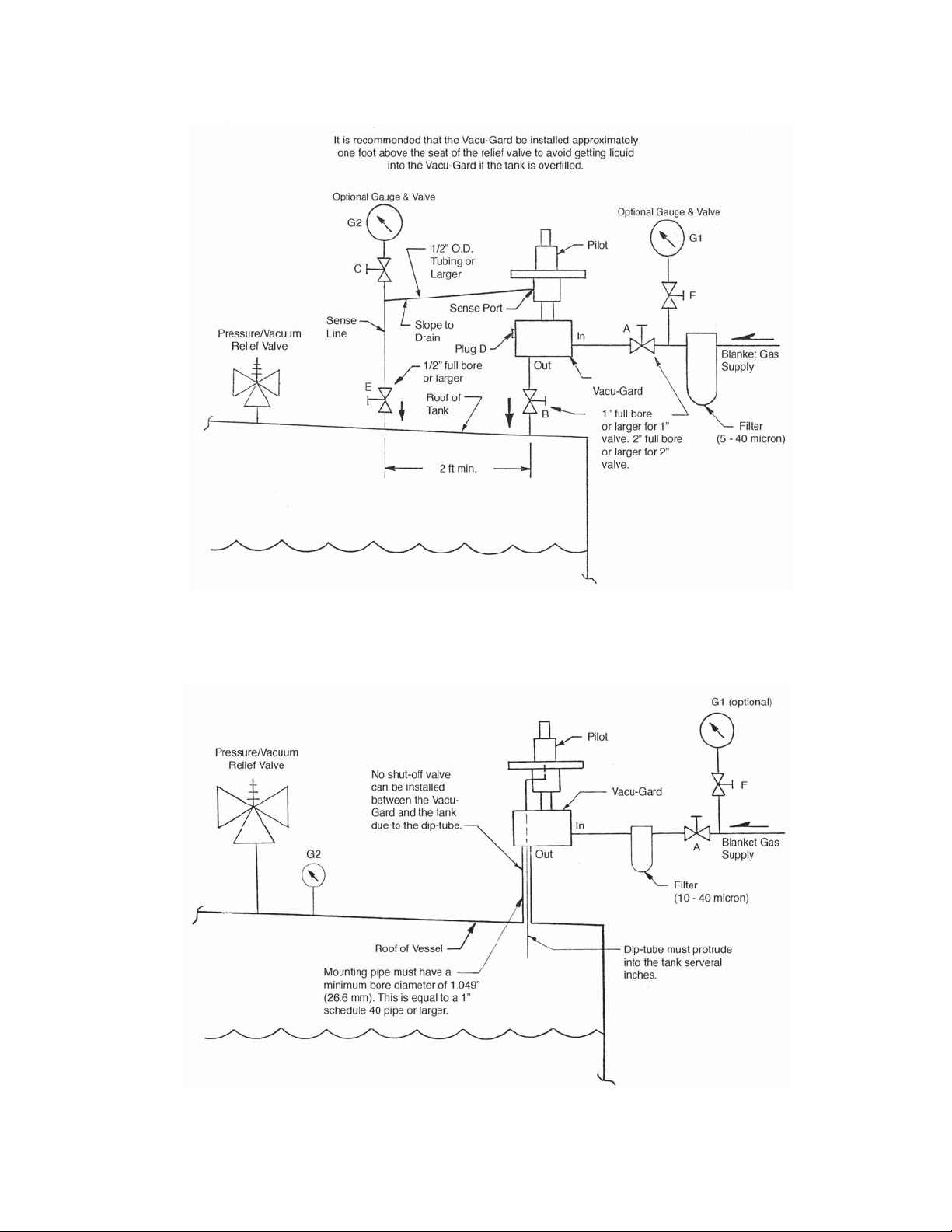
Normal Installation - Remote Sensing
Model 1078 Pilot Operated Vacu-Gard
Installation - with Integral Dip-Tube Sensing
Model 1078 Pilot Operated Vacu-Gard
3IOM-1078
Page 4
SECTION VI
VI. MAINTENANCE
The Model 1078 should be periodically actuated and
all sliding surfaces and seals lubricated to ensure
smoothness of operation. The frequency required
depends on the severity of the service conditions. At
least once a year is recommended.
CAUTION
If the valve must be disassembled for any reason,
fi rst make sure all pressure to the blanketing valve is
blocked and any pressure trapped in the valve is vented safely out. Refer to your company procedure for
any special precautions when handling toxic or other
hazardous materials.
Refer to the appropriate drawings for disassembly.
Pilot Internals: NOTE: The working components and
o-rings within the pilot body may be inspected and
replaced without the need to take apart the diaphragm
case. To remove the body internals, simply remove the
tubings (115) and unscrew the pilot body (038) from
the pilot mount (037)(on 1” valve) or from the pilot
connector (047)(on 2” valve). NOTE: Be careful not
to drop internal components. The return spring (025)
could dislodge the spindle (020) as the body and pilot
mount separate.
CAUTION
If the piston (107) does not remain in the main body
cavity, it may slowly slide out from the housing. Make
sure the piston does not fall out of the housing while
retracting the housing from the main body.
mount (037) upwards to remove from the main body.
The piston (107) and other internal parts should come
out with the pilot mount. To access the o-rings (105,
106), pull the piston (107) out of the pilot mount and
remove the screw (111) and lock washer (112). The
fl ow plug (109) will come out with a straight pull.
2” SIZE VALVES: Remove the six cap screw (129)
and lock washers (130) holding the piston housing (124)
to the main body. Carefully lift the pilot housing (124)
upwards to remove from the main body. To access
the o-rings (105,106), pull the piston (107) out of the
piston housing or remove it from the main body cavity.
Remove cap screw (011) and lock washer (012). The
fl ow plug (109) will come out with a straight pull.
To access seat ring seal (132), remove cap screws
(011) and lock washers (012) from seat ring (131).
Remove the seat ring from the main body. If the seat
ring is diffi cult to remove, thread two cap screws into
the threaded holes and remove the seat ring by lifting
upwards on the cap screws.
To Disassemble the Diaphragm Case Assembly:
Relax the compression on spring (007) by fi rst
unscrewing the cap (001). Rotate the jam nut (003)
CCW two rotations and then back out the adjusting
screw (002). Remove nuts (015), lock washers (012),
fl at washers (041) and cap screws (011) from around
the diaphragm case (009). Lift up to remove upper case
assembly, ring gasket (014) and diaphragm assembly.
Remove cap screws (011) and lock washers (012) from
the upper and lower cases to replace gaskets (008).
At re-assembly torque cap screws 13-15 ft-lbs.
To Disassemble Pilot Diaphragm Assembly:
Secure head of center bolt (017) in soft jawed vise.
Rotate nut (015) CCW. Remove nut, fl at washers (033)
and lock washer (012). Lift up to remove upper support
plate (016), gasket (018) and diaphragm (013). Lift up
to remove lower support plate (016) and gasket (018).
To Disassemble the Main Valve Assembly:
1” SIZE VALVES: Remove the four cap screws
(011) and washers (012, 041) holding the mounting
plate (036) to the main body. Carefully lift the pilot
Replace all parts that show signs of damage or excessive
wear. Make sure the material for new parts is suitable
for the service, especially elastomeric components.
If an o-ring needs to be replaced, be sure to use the
correct size and material. Prior to reassembly, make
sure all parts are clean and free of contamination and
seating surface is free of scratches.
CAUTION
DO NOT overtighten threaded connections since damage or breakage may result. Wrap all NPT threads with
TFE tape. Apply anti-seize compound on bolt threads.
Very lightly lubricate all o-rings with a lubricant that is
compatible with the service, sealing surfaces of gaskets and diaphragms also.
Reassemble in reverse order - utilize specifi c
instructions as follows for:
DIAPHRAGM CASE ASSEMBLY: Ensure center
bolt (017) is installed with the threaded end up. Install
one bolt gasket (018) between the center bolt and the
lower support plate (016) as shown on the drawing. An
identical gasket is used between the upper surface of
the sense diaphragm (013) and the bottom side of the
upper support plate. This is to ensure a tight squeeze
4 IOM-1078
Page 5

on both sides of the sense diaphragm to effect a tight
seal. Position ring gasket (014) on the top side of the
sense diaphragm. Install washers (033), lockwasher
(012) and nut (015). Torque nut 13-15 ft-lbs. Washers
are used to center the lower end of the spring. It may
sometimes be necessary to “thread” the spring onto
the washer or onto spring button (006). NOTE: You will
fi nd that turning the end of the spring in one direction
against the spring button or washers will tend to close
the coils and make installation more diffi cult. However,
turning the spring in the opposite direction will tend to
open the coils for easier installation.
PILOT INTERNALS: Before installation, ensure
o-ring (035) is placed around the groove adjacent to
the threads on pilot mount (037)(on 1” valve) or on
pilot connector (047)(on 2” valve). Install o-ring (021)
around the outside groove of the spindle (020). Install
o-ring (022) in the internal groove at the lower end of
the spindle. NOTE: O-RINGS (021,022) MUST BE
ORDERED FROM THE FACTORY.
To install the internals, turn the pilot body upside down
and insert the spindle (020) into the body with the small
diameter tip fi rst. Insert the spacer (026) and press it
down to the bottom of the body cavity. Insert return
spring (025) into the spindle cavity. Insert guide pin
(024) into the spring. Place the mounting plate (036)
around the pilot mount (037)(1” valve only). Place the
center cavity of the pilot mount (037)(1” valve) or pilot
connector (047)(2” valve) over the spring. Slowly and
carefully push against the spring to engage the threads
on the pilot mount or connector. Tighten until snug.
MAIN VALVE: Lightly lubricate all o-rings as mentioned
above. Prior to installing the fl ow plug, place o-ring
(106) on the piston (107). Install o-ring (105) in the
recess at the upper end of the fl ow plug (109). Grasp
the fl ow plug and push it into the shallow cavity of the
piston. Making sure to use the lock washer (item 112
for the 1” valve, item 012 for the 2” valve), install the
screw(111)(1” valve) or the bolt (011)(2” valve). For 1”
size torque the screw to 8-10 ft-lbs. For 2” size torque
the bolt to 13-15 ft-lbs. NOTE: The size of the fl ow plug
is stamped on the fl at end. See TABLE 1.
For 1” valves. Install o-ring (135) in the groove
inside the pilot mount (037). Next install o-ring (103)
around the groove on the piston (107). Lightly grease
the O.D. of the piston and the I.D. of the pilot mount.
Be sure that o-ring (104) is placed under the fl ange of
the pilot mount. Insert the spring (102), followed by the
piston, into the pilot mount. Push the piston in against
the spring several times to ensure there is no undue
binding. Guide the pilot mount, with the piston inside,
straight into the main body cavity. Install the four fl at
washers (041), lock washers (012) and cap screws
(011). Before the fi nal tightening of the bolts, it is a
good idea to check the tightness of the pilot mount in
the pilot body. To do so, tighten the bolts enough to
hold the pilot mount against the main body to prevent
the mount from turning. Then grasp the O.D. of the
pilot case by hand and turn it clockwise to tighten. After
tightening the mount into the pilot body, loosen the
bolts and turn the mount to orient the pilot ports in the
proper direction. Tighten the cap screws to 13-15 ft-lbs.
and reinstall all tubing. Make sure all tubing is clean
and unobstructed.
For 2” valves. Install the seat o-ring (132) in the
groove in the main body cavity. Place seat ring (131)
over the o-ring and use the four lock washers (012) and
cap screws (011). Be sure the fl at side of the seat ring
is up. Torque cap screws to 13-15 ft-lbs.
Grease the O.D. of the piston (107) and I.D. of the
piston housing (124). Install o-ring (135) in the groove
in the piston housing. Next install o-ring (103) around
the groove in the piston (107). Before placing the piston
into the main body cavity, ensure the o-ring (135) seats
properly into the piston housing and the piston can
slide smoothly in the housing. To check this, insert
the spring (102), followed by the piston, into the piston
housing. Push the piston in against the spring several
times to ensure there is no undue binding. If there is
no binding, the piston can then be removed from the
housing and placed in the main body.
Place the piston on the seat ring in the main body
cavity. Then place the spring (102) into the cavity of
the piston (107). Be sure that o-ring (104) is placed
under the fl ange of the piston housing. Carefully guide
the piston housing straight into the main body cavity,
making sure the piston slides properly into the housing.
Align the ports, and use the six lock washers (130) and
cap screws (129) to secure the housing.
Before the fi nal tightening of the bolts, it is a good idea
to check the tightness of the pilot connector to the pilot
body, the pilot connector to the piston housing, and the
alignment of the pilot ports. To do so, grasp the O.D.
of the pilot case by hand and turn it clockwise to tighten
while holding the pilot connector (047) in place. If the
pilot ports need re-positioning, use a combination of
tightening the pilot connector onto the piston housing
and/or rotating the piston housing one bolt hole.
Tighten the cap screws to 15-18 ft-lbs. Reinstall all
tubing, ensure it is clean and unobstructed.
After the valve has been completely reassembled, it
should be checked for set point pressure and any signs
of leakage. If the valve will not shut off tight, check for
dirt or other foreign particles on the o-rings or seating
surfaces. Also check to make sure the body internals
have not been damaged.
5IOM-1078
Page 6

TABLE 1
Identifi cation Grooves for reduced fl ow plugs for verifi cation when the valve is fully assembled.
1” and 2” Vacu-Gards
Flow plugs are steel stamped with their size on the fl at tip as follows:
1” Valve 2” Valve
100 100
75 80
50 60
25 40
10 20
This number represents the percentage of maximum fl ow that is allowed through the valve. The number is marked
on the fl at tip of the plug and is not visible when the valve is assembled. Therefore all fl ow plugs (except the 100%
plug) are marked with circumferential grooves that are visible from the inlet port of a fully assembled valve. The
identifying grooves are as follows:
FLOW PLUG SIZE
No. of Grooves 1” Valves 2” Valves
None 100% (barely visible) 100% (not visible)
1 75% 80%
2 50% 60%
3 25% 40%
4 10% 20%
SECTION VII
VII. ORDERING INFORMATION:
NEW REPLACEMENT UNIT vs PARTS "KIT" FOR FIELD REPAIR
To obtain a quotation or place an order, please retrieve the Serial Number and Product Code that was
stamped on the metal name plate and attached to the unit. This information can also be found on the Bill of
Material (parts list) that was provided when unit was originally shipped.) (Serial Number typically 6 digits).
NEW REPLACEMENT UNIT:
Contact your local Cashco, Inc., Sales Rep re sen ta tive with the Serial Number, Product code and the
pressure/vacuum settings. With this information they
can provide a quotation for a new unit including a
complete description, price and availability.
CAUTION
Do not attempt to alter the original construction of any
unit without assistance and approval from the factory.
All purposed changes will require a new name plate with
appropriate ratings and new product code to accomodate the recommended part(s) changes.
PARTS "KIT" for FIELD REPAIR:
Contact your local Cashco, Inc., Sales Rep re sen ta tive with the Serial Number and Product
code. Identify the parts and the quantity
required to repair the unit from the Bill of Materials sheet that was provided when unit was
originally shipped.
NOTE: Those part numbers that have a quantity
indicated under "Spare Parts" in column "A”
refl ect minimum parts required for inspection
and rebuild, - "Soft Goods Kit". Those in column “B” include minimum trim replacement
parts needed plus those "Soft Goods" parts
from column "A".
If the "BOM" is not available, refer to the crosssectional drawings included in this manual for
part identifi cation and selection.
Local Sales Representative will provide quotation for appropriate Kit Number, Price and
Availability.
6 IOM-1078
Page 7

SECTION VIII
VIII. TROUBLE SHOOTING GUIDE
1. Vacu-Gard will not open.
Possible Cause Remedy
A. Incorrect sense line connection. A1.
B. Sense line is clogged. B1. Check sense line and sense port for blockage.
C. Improper inlet and/or outlet connection. C1. Check and be sure supply line is connected to inlet of Vacu-
D. Loss of supply pressure. D1. Check supply pressure and see that it is within the range
2. Vacu-Gard will not close.
Possible Cause Remedy
A. Sense line not installed. A1. Check that the sense line is properly connected.
Check sense line and be sure it is connected from the sense
port on the Vacu-Gard to the tank.
A2.
Check sense line and shut-off valve for size and confi guration
to prevent pressure drops and trapped condensate.
Gard and outlet of Vacu-Gard is connected to tank, making
sure it is not reversed.
stated on nameplate.
B. Vacu-Gard set pressure is higher than or too close to
the set pressure of the pressure relieving devices.
C. Blanket gas is escaping from opening in tank. C1. Be sure all openings such as pressure relieving devices,
D. Malfunction of pressure relieving devices. D1. Check operation of pressure relieving devices.
E. Blanket gas is escaping from faulty piping or con-
nections.
F. Foreign particles trapped in Vacu-Gard. F1. Check Vacu-Gard for dirt and debris. (See Maintenance
G. Pilot inlet port is clogged. G1. Check pilot inlet port, fi lter and tubing.
H. Vacu-Gard has loose connections. H1. Check and make sure all Vacu-Gard connections are
B1. Check settings of valves and adjust if needed. The pressure
relieving devices must be set higher than the Vacu-Gard
setting. The greater the spread the better.
gauge hatches, etc., are closed and working properly.
E1. Check all piping and connections for tightness.
Section for disassembly and reassembly.)
tight.
3. Vacu-Gard cycles rapidly.
Possible Cause Remedy
A. Shut-off valve at outlet is restricting fl ow. A1. Be sure shut-off valve at outlet is full bore or larger.
B. Vacu-Gard set pressure too close to the set pressure
of the pressure relieving devices.
C. Sense or fl ow line pipe is undersized. C1. Check all piping connected to Vacu-Gard for size and confi gu-
B1. Check settings of valves and adjust if needed. The pressure
relieving devices must be set higher than the Vacu-Gard.
ration to prevent pressure drops and trapped condensate.
4. Vacu-Gard closes but will not shut-off tight.
Possible Cause Remedy
A. Worn o-rings or seat surfaces. A1. Replace worn parts. (See Maintenance Section for disas-
sembly and reassembly.)
B. Foreign particles on o-rings or seat surfaces. B1. Clean and lubricate parts. (See Maintenance Section for
disassembly and reassembly.)
C. Loose connections on Vacu-Gard. C1. Check all connections for tightness.
7IOM-1078
Page 8

Pilot Assembly for 1” Model 1078
ITEM NO. QUANTITY PART NAME
001 1 Cap
002 1 Adjusting Screw
003 1 Jam Nut
004 1 Vent
005 1 Spring Bonnet
006 1 Spring Button
007 1 Set Pressure Spring
008 2 Gasket ‡
009 2 Diaphragm Case
011 24
012 25 Lockwasher
013 1 Sense Diaphragm ‡
014 1 Ring Gasket ‡
015 17 Nut
016 2 Support Plate
017 1 Center Bolt
018 2 Bolt Gasket
020 1 Spindle
021 1 O-Ring ‡
022 1 O-Ring ‡
024 1 Guide Pin
025 1 Return Spring
026 1 Spacer
033 2 Washer
035 1 O-Ring ‡
036 1 Mounting Plate
037 1 Pilot Mount
038 1 Pilot Body
041 32 Washer-fl at
‡ Typical Parts required for inspection and rebuild.
Cap Screw
8 IOM-1078
Page 9

Main Valve Assembly for 1” Model 1078
ITEM NO. QUANTITY PART NAME
011 4 Cap Screw
012 4 Lockwasher
041 4 Washer-Flat
101 1 Pilot Valve Assy.
102 1 Spring
103 1 O-Ring ‡
104 1 O-Ring ‡
105 1 O-Ring ‡
106 1 O-Ring ‡
107 1 Piston
108 1 Main Body
109 1 Flow Plug
110 1 Strainer
111 1 Screw
112 1 Lockwasher
113 1 Tube Fitting - Elbow
ITEM QUANTY DESCRIPTION
114 2 Tube Fitting
115 2 Tubing
116 1 Pipe Plug
117 1 Pipe Plug
118 1 Thermocouple Fitting
119 1 Nameplate
120 2 Drive Screw
135 1 O-Ring ‡
201 1 Nipple
202 1 Filter Assy.
‡ Typical Parts required for inspection and rebuild.
9IOM-1078
Page 10

Pilot Assembly for 2” Model 1078
ITEM NO. QUANTITY PART NAME
001 1 Cap
002 1 Adjusting Screw
003 1 Jam Nut
004 1 Vent
005 1 Spring Bonnet
006 1 Spring Button
007 1 Set Pressure Spring
008 2 Gasket ‡
009 2 Diaphragm Case
011 24 Cap Screw
012 25 Lockwasher
013 1 Sense Diaphragm ‡
014 1 Ring Gasket ‡
015 17 Nut
016 2 Support Plate
017 1 Center Bolt
018 2 Bolt Gasket ‡
020 1 Spindle
021 1 O-Ring ‡
022 1 O-Ring ‡
024 1 Guide Pin
025 1 Return Spring
026 1 Spacer
033 2 Washer
035 1 O-Ring ‡
038 1 Pilot Body
041 32 Washer-fl at
047 1 Pilot Connector
‡ Typical Parts required for inspection and rebuild.
10 IOM-1078
Page 11

Main Valve Assembly for 2” Model 1078
ITEM NO. QUANTITY PART NAME
011 5 Cap Screw
012 5 Lockwasher
101 1 Pilot Valve Assembly
102 1 Spring
103 1 O-Ring ‡
104 1 O-Ring ‡
105 1 O-Ring ‡
106 1 O-Ring ‡
107 1 Piston
108 1 Main Body
109 1 Flow Plug
110 1 Stainer
114 2 Tube Fitting
ITEM QUANTY DESCRIPTION
115 2 Tubing
116 1 Pipe Plug
117 1 Pipe Plug
118 1 Thermocouple Fitting
119 1 Nameplate
120 2 Drive Screw
124 1 Piston Housing
129 6 Cap Screw
130 6 Lockwasher
131 1 Seat Ring
132
135 1 O-Ring ‡
201 2 Nipple
202 1 Filter Assembly
308 1 Tube Fitting-Female Elbow
‡ Typical Parts required for inspection and rebuild.
1 Seat Ring Seal ‡
11IOM-1078
Page 12

Valve Concepts, Inc./ Cashco, Inc.
607 W. 15th Street
Ellsworth, KS 67439
PH (785) 472-4461
FAX (785) 472-3539
www.cashco.com
email: vcisales@cashco.com
Printed in U.S.A. Model 1078-IOM
 Loading...