


cashco 1000HP, 1000HP-5, 1000HP-36 Installation, Operation & Maintenance Instructions Manual
INSTALLATION, OPERATION & MAINTENANCE MANUAL
ISO Registered Company
IOM-1000HP-
MODEL 1000HP - CRYOGENIC
PRESSURE REDUCING REGULATOR
SECTION I
I. DESCRIPTION AND SCOPE
The Model 1000HP-5 and 1000HP-36 are cryogenic pressure reducing regulators used to control down stream
(outlet or P
1-1/2" and 2".
The unit is designed for liquid or gaseous service with proper trim utilization, and proper jet selection.
Refer to Technical Bulletin 1000HP-CRYO-TB for sizing, application and selection recommendations.
Installation, operation and maintenance manuals (IOM's) exist for the following other Model 1000 products:
1000HP-Basic 1000LP-Basic 1000HP-Differential
) pressure to levels above 10 psig, and up to 300 psig (size dependent). Sizes are 1/2", 3/4", 1",
2
Cryogenic
12-16
II. INSTALLATION
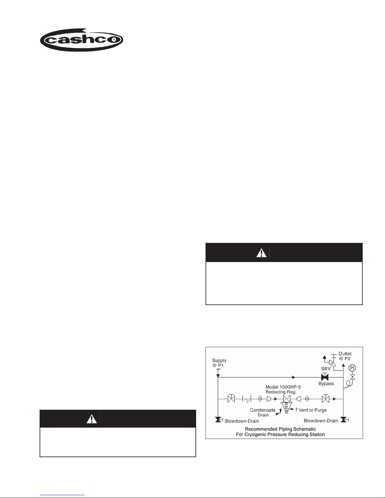
1. An inlet block valve should always be in stalled.
2. If service application is continuous such that
shut down is not readily accomplished, it is
rec om mended that an inlet block valve, and a
manual bypass valve be in stalled.
3. Pipe unions must be installed to allow re mov al
from piping. Trim can only be changed by unit
removal from pipeline. If flanges are uti lized, a lap
joint flange is required on the inlet end of the valve
to help align bolt holes as the cylinder screws into
place.
4. An outlet pressure gauge should be located
ap prox i mate ly ten pipe diameters down stream,
and within sight.
5. All installations should include a down stream
relief de vice if the inlet pressure could exceed the
pressure rating of any downstream equip ment or
the maximum outlet pressure rat ing of the unit.
SECTION II
WARNING
The maximum outlet pressure listed on the name plate is
the "upper operative limit" for the sensing diaphragm.
Higher pressures could damage the diaphragm. (Field
hy dro static tests frequently de stroy dia phragms. DO NOT
HY DRO STAT IC TEST THROUGH AN INSTALLED UNIT;
ISO LATE FROM TEST.)
6. Clean the piping of all foreign ma te ri al in clud ing
chips, welding scale, oil, grease and dirt before
in stall ing the valve. Strain ers are rec om mended.
CAUTION
Installation of adequate overpressure pro tec tion is
recommended to pro tect the reg u la tor from over pres sure
and all down stream equip ment from dam age in the event
of regulator failure.

7. In placing thread sealant on pipe ends prior to
en gage ment, ensure that excess material is
removed and not allowed to enter the regulator
upon startup.
8. Flow Direction: Install so the flow direction
match es the arrow cast on the body.
9. For best performance, install in well drained
hor i zon tal pipe. Recommended position is with
spring chamber vertically downwards. Orient
to prevent the spring cham ber vent hole from
collecting rainwater or debris, and so drain hole
SECTION III
III. PRINCIPLE OF OPERATION
1. The Model 1000 is available in two vari a tions:
1000LP (larger diaphragm) for down stream pressure control from 1-30 psig; 1000HP (small er
diaphragm) for down stream pressure control from
10-300 psig, body size dependent.
2. Movement occurs as pressure variations register on the diaphragm. The registering pres sure
is the outlet, P
range spring opposes di a phragm move ment. As
outlet pressure drops, the range spring pushes
the diaph ragm up, opening the port; as outlet
pressure increases, the dia phragm push es down
and the port closes.
3. The Model 1000 includes a rocker arm in its
op er a tion al mechanism. The rocker arm allows
the regulator to operate flow-to-open (FTO),
rather than conventional flow-to-close (FTC),
which increases rangeability.
4. Due to the FTO design, there is a limit as to how
low of a downstream (P
setting is capable for a given inlet P
, or downstream pressure. The
2
or outlet) pressure level
2
pressure.
1
can drip melted condensate as re quired. A purge
gas is recommended for the spring cham ber.
10. Regulators are not to be direct buried underground.
11. For insulated piping systems, recommen dation is
to not insulate regulator.
12. Cashco does not recommend field welding on
the cyl in der (inlet) end of the regulator, due to the
possibility of warpage.
This is a function of the ratio of the port area to
di a phragm area. It is possible for there to be too
high of an inlet pressure for the regulator to close
off against. (Refer to Technical Bulletin, Tables 6
and 7 for limits.) Reduced port, Option -12 allows
low er down stream (P
or outlet) pressure set tings
2
for a given up stream (P1 or inlet) pressure level.
5. The FTO design also is limited by a minimum
pressure drop. If the regulator pressure drop is
below 5 psi, an Option 1000-17 Piston Spring
should be utilized to assist open ing the valve
piston. (Standard with 1000-5; must be speci fied
with 1000-36.)
6. The Model 1000 includes an aspiration jet ef fect,
due to the clearance of the piston from the body
near the regulator's outlet. These clear ances vary
as to whether the fluid is a gas or a liquid. Jets must
be se lec ted to match one of these two general
fluids. An improper jet selection will reduce performance.
7. A complete diaphragm failure will cause the
regulator to fail open.
2 IOM-1000HP-Cryogenic

SECTION IV
IV. STARTUP
1. Purge the system, including the spring cham ber,
to remove air, moisture, carbon dioxide, etc.
2. Start with the block valves closed. A bypass
valve may be used to maintain outlet pressure
in the downstream system without changing the
fol low ing steps.
3. Relax the range spring by turning the adjusting
screw counterclockwise (CCW) a min i mum of
three (3) full revolutions. This re duces the outlet
(down stream) pres sure set point. NOTE: Ro ta tion
CW or CCW is as viewed from the ad just ing screw
end, i.e. bottom of valve looking up.
4. If equipped with a bypass valve, slowly open
the bypass valve to cool the system piping and
to allow slow contraction of the piping. Closely
monitor outlet (down stream) pressure via gauge
to ensure not over-pres sur iz ing. NOTE: If no
bypass valve is in stalled, extra caution should
be used in starting up an am bi ent tem pera ture
system; i.e. do everything slow ly.
5. Crack open the outlet (downstream) block valve.
6. Slowly open the inlet (upstream) block valve
ob serv ing the outlet (down stream) pres sure
gauge. Determine if the regulator is flowing. If
not, slowly rotate the reg u la tor ad just ing screw
clockwise (CW) until flow begins.
7. Continue to slowly open the inlet (up stream) block
valve until fully open.
8. Continue to slowly open the outlet (down stream)
block valve, especially when the down stream
piping system isn't pres surized. If the outlet
(downstream) pressure exceeds the de sired
pres sure, close the block valve and go to Step 2,
then return to Step 4.
9. When flow is established steady enough that the
outlet (downstream) block valve is fully open,
begin to slowly close the bypass valve if in stalled.
10. Develop system flow to a level near its expected
normal rate, and reset the regulator set point by
turning the adjusting screw CW to increase outlet
pressure, or CCW to reduce outlet pres sure.
11. Reduce system flow to a minimum level and
ob serve set point. Outlet pressure will rise from
the set point of Step 9. The maximum rise in
outlet pressure on decreasing flow should not
exceed the stated up per limit of the range spring
by greater than 30%; i.e. 10-40 psig range spring,
at low flow the outlet pressure should not exceed
52 psig. If it does, consult fac to ry.
V. SHUTDOWN
1. On systems with a bypass valve, and where
sys tem pressure is to be maintained as the
reg u la tor is shut down, slowly open the by pass
valve while clos ing the inlet (up stream) block
valve. Fully close the inlet (up stream) block valve.
(When on bypass, the system pres sure must be
con stant ly observed and man u al ly reg u lat ed.)
Close the outlet (down stream) block valve.
VI. MAINTENANCE
A. General:
1. Maintenance procedures hereinafter are
based upon removal of the regulator unit
from the pipeline where in stalled.
SECTION V
2. If the regulator and system are to both be
shut down, slowly close the inlet (upstream) block
valve. Close the outlet (down stream) valve only if
regulator re mov al is required.
CAUTION
Do not walk away and leave a bypassed regulator unattended.
SECTION VI
2. Owner should refer to owner's proce dures for
removal, handling and cleaning of reusable
parts, and disposal of nonreusable parts, i.e.
asbestos gaskets, suitable sol vents, etc.
IOM-1000HP-Cryogenic
3
3. If desired, gaskets may be oiled, or coated with
gasket sealant or thread sealing com pound,
pro vid ed the sealant is compatible with
the fluid. (See below for "oxygen cleaned"
valves.)
4. Valves originally supplied as "oxygen
cleaned" (Options 1000-55, 1000-5 or 1000-
36) are as sem bled using special gasket
sealant, Fluorolube GR-362
Cashco, Inc. recommends following fac to ry
cleaning spec ification #S-1134, or equiv a lent.
Con tact factory for details.
B. Diaphragm Replacement:
1
, or equivalent.
1. Securely install the body (1) in a vise with the
spring chamber (2) directed upwards.
2. Relax range spring (27) by turning ad just ing
screw (6) CCW until removed from spring
chamber (2).
3. Paint or embed a match mark between body
casting (1) and spring chamber cast ing (2)
along flanged area.
4. Remove all diaphragm nuts (9) and bolts (8).
Remove nameplate (28).
5. Remove spring chamber (2), range spring
(27) and spring button (4).
NOTE: The text hereafter will refer to "pusher plate and
stud (13)" as a single part, which it is for SST trim.
Brass trim uses a separate "push er plate (5)" and a
"pusher plate stud (13)", both of which are peened
together at initial as sem bly.
6. Pry up the diaphragm(s) (20) and diaphragm gasket (19) around the perimeter of the
body (1) diaphragm flange to ensure that the
diaphragm(s) (20) are not "stick ing".
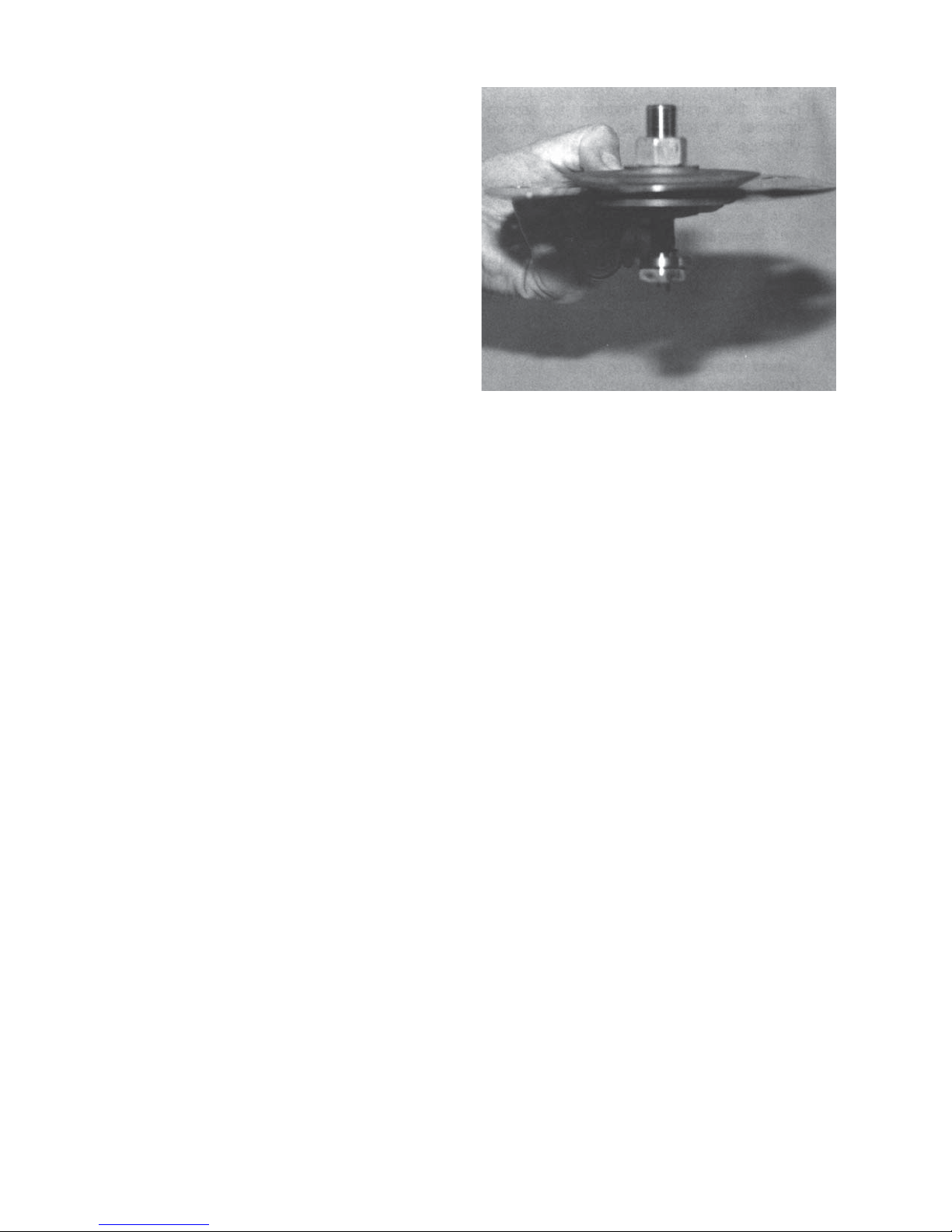
7. Remove the diaphragm sub-assembly by
slid ing the pusher plate and stud (13) and
nut (11) in the direction of the regulator's
inlet, approximately 1/2"-3/4". The pusher
plate and stud (13), stud nut (10), and stud
collar (16) should disengage with the rocker
arm (14) slot. Lift vertically for the diaphragm
sub-assembly removal.
Diaphragm sub-assembly consists of items (10), (11), (12),
(13), (15), (16) and (20).
8. Place the pusher plate stud (13) in a
sepa rate vise, gripping the stud (13) on the
hex ago nal cast-in-place edges located on
the un der neath side of the pusher plate stud.
NOTE: Do not remove the stud nut (10), stud
collar (16) and the location lock ing cotter pin
(15). Loosen and remove nut (11).
9. Remove pressure plate (3) by lifting.
10. Pry loose pusher plate and stud (13) from
diaphragm(s) (20) or from pusher plate gas ket
(12). Remove the diaphragm(s) (20).
11. Remove pusher plate gasket (12) from push er
plate and stud (13).
12. Clean gasket sealing surface of pusher plate
and stud (13) thoroughly.
13. Install new pusher plate gasket (12), if
re quired, over pusher plate and stud (13).
14. Install new diaphragm(s) (20) over pusher
plate and stud (13). NOTE: Refer to the
quantity of diaphragms (20) incorporated
per the bill of materials listing. Depending on
outlet pressure level, various quantities of
metal diaphragms will be "stacked".
4 IOM-1000HP-Cryogenic

15. Inspect pressure plate (3) to ensure no
de for ma tion due to over-pres sur iza tion.
If de formed, bent, or otherwise distorted,
re place.
16. Ensuring that the curved outer rim side
of the pressure plate (3) rests against the
dia phragm (20) directly, place the pressure
plate (3) over the pusher plate and stud (13).
Place nut (11) onto the stud (13) and tighten
to 35 ft.-lbs. torque for metal diaph ragm.
Use two flange bolts (8) to keep multiple
dia phragms' (20) bolt holes prop er ly aligned
while tightening the stud nut (10). (DO NOT
USE FINGERS TO HOLD DIAPHRAGMS
(20) DURING TIGHT EN ING OF NUT (11).)
17. Remove cotter pin (15) securing stud nut (10)
to lower end of pusher plate and stud (13), and
replace with a new pin (15). (Do not allow the
stud nut (10) to move when the cotter pin (15)
is removed.)
18. Remove rocker arm shaft (17) and rocker
arm (14). Measure inside of rocker arm (14)
"prongs" as indicated below:
19. Check rocker arm shaft (17) for wear and
straightness. Replace if damaged. Rein stall
in body (1) through rocker arm (14). Apply
thread sealant to the rocker arm shaft (17)
threads prior to tightening. Make sure that the
rocker arm shaft (17) enters the support slot
op po site the threaded open ing, and does not
align crooked and restrained from full thread
engagement of the rocker arm shaft (17).
Make sure that the rocker arm (14) prongs that
straddle the piston (24) hold the piston collar
(23) against the piston (24); do not allow the
rocker arm (14) prongs to push directly on the
piston (24).
20. Clean the body (1) diaphragm flange. Seal ant
may be applied to the body (1) flange prior
to diaphragm (20) placement. Install a new
diaphragm gasket (19).
21. Using small gauge wire approximately 18"
long, form a hook, and place the hook over
one prong of the rocker arm (14), and rotate
the rocker arm (14) up until slack is re moved
in the mechanism. Secure the wire through a
body (1) flange bolt hole on the outlet side of
the regulator.
Dim. Mat'l
A BR 7/8" 1-5/32" 1-7/16"
B BR 5/8" 25/32" 3/4"
A SST 13/16" 1-1/16" 1-7/16"
B SST 9/16" 23/32" 3/4"
1/2" 3/4" 1" 1-1/4" 1-1/2" 2"
Valve Size
1-13/16" 1-25/32" 2-3/16"
29/32" 7/8" 29/32"
1-1/2" 1-25/32" 2-5/32"
11/16" 7/8" 29/32"
22. Take the diaphragm sub-assembly (Step 16)
and lower it down into the body (1) cavity
off-center approximately 3/4"-1" and to wards
the inlet side of the regulator. When fully
lowered, slide the diaphragm sub-as sem bly
horizontally towards the regulator's outlet.
The wire of Step 21 should hold the rocker
arm (14) up to allow engaging of the pusher
plate and stud (13) (with stud nut (10) and stud
collar (16)), so the rocker arm (14) prongs rest
directly on the stud collar (16). (Do not allow
the rocker arm (14) prongs to get between
the stud nut (10) and the stud collar (16).)
Pull firmly to remove wire holding rocker arm
(14) up.
23. Align diaphragm (20) bolt holes with body (1)
flange bolt holes. Set range spring (27) onto
pressure plate (3), place spring button (4) on
top of range spring (27). Place cryo gen ic,
multi-purpose temp erature lubricant into
depression of spring button (4).
If either of the above dimensions are
ex ceeded by 1/8", re place rocker arm
(14).
IOM-1000HP-Cryogenic
5