

cashco 1000HP, 1000HP-1PLUS6, 1000HP-1PLUS8 Installation, Operation & Maintenance Manual
INSTALLATION, OPERATION & MAINTENANCE MANUAL
ISO Registered Company
IOM-1000HP-
Differential
MODEL 1000HP - DIFFERENTIAL
PRESSURE REDUCING REGULATOR
SECTION I
I. DESCRIPTION AND SCOPE
The Model 1000HP-1+6 and 1000HP-1+8 are dif fer en tial pressure reducing regulators used to control dif fer en tial
pressure between downstream (outlet or P2) pressure and a loading (P
are 1/2" , 3/4", 1", 1-1/4", 1-1/2" and 2" (DN15, 20, 25, 32, 40 and 50). With proper trim uti li za tion and jet selection,
this unit is suitable for liquid, gaseous, or steam service. Refer to Technical Bulletin 1000HP-DIFF-TB for sizing,
application and selection rec om men da tions.
SECTION II
II. INSTALLATION
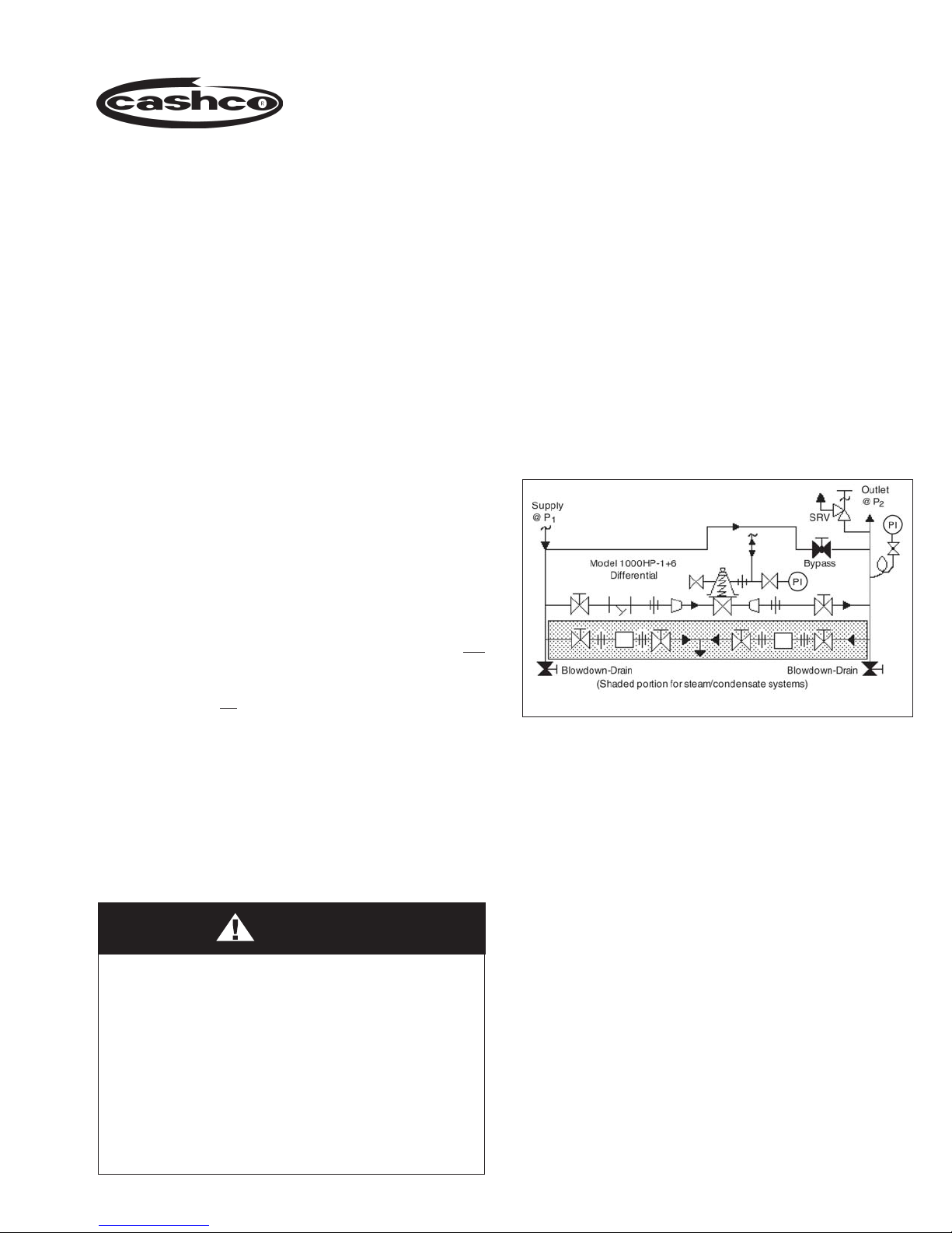
1. An inlet block valve should always be installed.
An outlet block valve is desirable.
) pressure to the spring chamber. Sizes
Load
01-17
2. A manual bypass valve is recommended for “hot
piping” systems to assist in piping warm-up at
startup.
3. An isolation valve on the loading line is not
rec om mend ed. The annular body ring of the
1000HP-1+8 may be piped to a safe drainage
point, but no valve should be installed in the drain
line.
4. Pipe unions must be installed to allow removal from
piping. Trim can only be changed by unit removal
from pipeline. If flanges are utilized, a lap joint
flange is required on the inlet end of the regulator
to help align bolt holes as the cylinder screws into
place. NOTE: Cashco does not rec om mend field
welding on the cylinder (inlet) end of the valve due
to the possibility of warpage.
CAUTION
DO NOT HYDROSTATIC TEST THROUGH AN
IN STALLED UNIT; ISOLATE FROM TEST. DO NOT
HY DRO STAT IC TEST THE LOADING PRESSURE
WITH OUT PRESSURE IN THE MAIN REGULATOR.
The name plate indicated outlet pressure rating, if
reached, may cause internal damage. Refer to Tech ni cal
Bulletin Model 1000HP-DIFF-TB, Table 3 for “emer gen cy
overpressure level” that will not do irreparable internals
damage. In addition, note on the name plate that the
Inlet and Outlet pressure and tem per a ture ratings are
at different levels.
Recommended Piping Schematic for
Differential Pressure Reducing Station
5. An outlet pressure gauge should be located
ap prox i mate ly ten pipe diameters downstream,
and within sight. A loading pressure (or differential
pressure) gauge is rec om mend ed.
6. All installations should include a downstream
re lief device if the inlet pressure could exceed the
pressure rating of any downstream equipment or
the maximum outlet pressure rating of the unit.
7. Clean the piping of all foreign material including
chips, welding scale, oil, grease and dirt
before in stall ing the regulator. Strainers are
rec om mend ed.
8. In placing thread sealant on pipe ends prior to
en gage ment, ensure that excess material is
re moved and not allowed to enter the regulator
upon startup.
9. Flow Direction: Install so the flow direction match es
the arrow cast on the body.

10. For best performance, install in well drained
hor i zon tal pipe, properly trapped if a steam ser vice
ap pli ca tion.
diaphragm design): Regulator may be rotated
around the pipe axis 360° and may be installed
in a horizontal or vertical pipeline.
11. Differential Regulator – (Refer to Dwg. Opt-1+6
for single diaphragm or Dwg. Opt-1+8 for double
III. PRINCIPLE OF OPERATION
1. The differential Model 1000HP is also available
in two options: 1000HP-1+6 is single diaphragm
con struc tion; 1000HP-1+8 is double diaphragm
con struc tion. The dou ble diaphragm construction
prevents the loading fluid from direct mixing with
the system fluid in case of di a phragm failure.
2. Movement occurs as pressure variations register
on the diaphragm. One pressure is the outlet (p
or down stream pressure, which registers on the
“un der neath” side of the diaphragm. The second
pressure reg is tered is the loading (P
in the spring chamber “above” the di a phragm.
The range spring determines the differential
pres sure level (P
). As outlet (P2) pressure
Set
drops, the range spring pushes the diaphragm
down, open ing the port; as outlet (P
in creas es, the diaphragm pushes up and the port
closes. As the loading (P
) pressure varies, the
Load
outlet (P2) pressure tends to follow. An increase
in P
Load
(∆P
) will increase outlet P2 pressure
Load
by near ly an equal amount (∆P
decrease in P
outlet P
pres sure.
2
will have a similar effect on
Load
) pres sure
Load
) pressure
2
= ∆P2); a
Load
12. Regulators are not to be direct buried un der ground.
SECTION III
)
2
∆P
P2 > P
P2 = P
∆P
5. The Model 1000 includes an aspiration jet effect,
due to the clearance of the piston from the body
near the outlet. These clearances vary as to
whether the fluid is a gas (including steam), a liquid,
or a viscous liquid (required Opt-27). Jets must
be selected to match one of these three general
fluids. An improper jet will reduce per for mance.
NOTE: The regulator requires minimum output
pressure level or the regulator will not close.
= P1 - P
Sizing
Load
Load
Differential
2
+ P
Set
= P2 - P
Load
1000HP-1+6
DIFFERENTIAL SCHEMATIC
RANGE SPRING:
SETTING @ P
Set
LOADING
FLUID @ P
Diaphragm
Load
OUTLET
@ P
2
& T
2
3. The Model 1000 includes a rocker arm in its
operation mechanism. The rocker arm allows the
regulator to op er ate flow-to-open (FTO), rather
than conventional flow-to-close (FTC), which
in creas es rangeability.
4. Due to the FTO design, there is a limit as to how
low of a downstream (P
or outlet) pressure level
2
setting is capable for a given inlet P1 pressure.
This is a function of the ratio of the port area to the
diaphragm area. It is possible for there to be too
high of an inlet pressure for the regulator to close
off against. (Refer to 1000HP-DIFF-TB, Ta bles 9,
10, 11 and 12 for limits.) Reduced port, Opt-12,
allows lower down stream (P
2
settings for a given upstream (P1 or inlet) pressure
level.
2
or outlet) pres sure
6. For a 1000HP-1+6 (single diaphragm) design, a
com plete diaphragm failure will cause the fluids
to mix in the spring chamber or loading pressure
piping system.
7. For a 1000HP-1+8 (double diaphragm) design, a
complete diaphragm failure will cause the reg u la tor
to fail open, leaking fluid through the annular ring
vent hole.
NOTE: Composition (soft) diaphragms may be
utilized only on -1+6 single diaphragm con struc tion.
8. For viscous fluids normally heated (heavy fuel
oil), it may be desirable to include a flow-through
spring cham ber, the -65 Option.
IOM-1000HP-Dif fer en tial
IV. STARTUP
SECTION IV
1. Start with the block valves closed. A by pass valve
may be used to maintain outlet pressure in the
down stream system without changing the fol low ing
steps.
2. Remove closing cap and relax the range spring
by turning the adjusting screw counterclockwise
(CCW) a minimum of three (3) full revolutions.
This reduces the outlet (downstream) pressure
set point.
3. If it is a “hot” piping system, and equipped with
a bypass valve, slowly open the bypass valve
to pre-heat the system piping and to allow slow
expansion of the piping. Ensure proper steam
trap operation if installed. Closely monitor outlet
(down stream) pressure, via gauge, to en sure not
over-pressurizing. NOTE: If no bypass valve is
in stalled, extra caution should be used in starting
up a cold system; i.e. do everything slow ly.
CAUTION
Do not walk away and leave a bypassed reg u la tor
unattended!
4. Crack open the outlet (downstream) block valve.
5. Slowly open the inlet (upstream) block valve
ob serv ing the outlet (downstream) pressure gauge.
De ter mine if the regulator is flowing. If not, slowly
rotate the regulator adjusting screw clockwise
(CW) until flow be gins.
6. Continue to slowly open the inlet (upstream) block
valve until fully open.
7. Continue to slowly open the outlet (downstream)
block valve, especially when the downstream
piping sys tem isn’t pressurized. If the outlet
(down stream) pressure exceeds the desired
pressure, close the block valve and go to Step 2,
then return to Step 4.
8. When flow is established steady enough that the
outlet (downstream) block valve is fully open, begin
to slowly close the bypass valve if installed.
9. Set the regulator set point (P
ad just ing screw clockwise (CW) to increase outlet
pres sure or CCW to reduce outlet pressure. The
outlet (P2) pressure under these conditions will
approximate the desired dif fer en tial pressure when
loaded with P
10. Pressurize the source of loading (P
and allow to fill the spring chamber cavity. Slightly
open the bleeder valve to vent any air as the spring
chamber is filling.
11. Develop system flow and pressure and readjust
set point as required to obtain desired response.
Per for mance should be analyzed at minimum and
maximum flow levels.
12. Install closing cap.
Load
.
) by turning the
set
) pres sure
Load
V. SHUTDOWN
CAUTION
Loading Pressure must be shut off before shut ting
down the system pressure.
1. To prevent force imbalances and possible
di a phragm failure, the loading pressure (P
should always be shutdown first from its source of
pres sure. Systems se quenc ing must ensure this
oc curs.
3
SECTION V
)
Load
2. It is recommended that manual operation not be
attempted by a bypass valve during a shutdown.
3. When the loading pressure (P
shut down, the regulator outlet pressure (P2) should
decrease substantially. When this is observed, the
inlet (upstream) block valve may be closed.
IOM-1000HP-Dif fer en tial
) has been
Load
VI. MAINTENANCE
SECTION VI
(19) is not used with a composition (soft)
diaphragm.)
WARNING
SYSTEM UNDER PRESSURE. Prior to per form ing
any maintenance, isolate the regulator from the
system and relieve all pressure. Failure to do so
could result in personal injury.
A. General:
1. Maintenance procedures hereinafter are based
upon removal of the unit from the pipeline
where installed.
2. Owner should refer to owner’s procedures for
re mov al, handling and cleaning of reusable
parts, and dis pos al of non-reusable parts, i.e.
gaskets.
3. If desired, the gaskets may be lubricated with
a light oil provided it is com pat i ble with the
fluid.
B. Diaphragm Replacement:
1. Securely install the body (1) in a vice with the
spring chamber (2) directed upwards.
NOTE: The text hereafter will refer to:
a. The -1+8 double di a phragm op tion al
con struc tion (-1+6 single di a phragm
con struc tion is sim i lar. Text regarding
com po si tion diaphragm(s) (20)
applies only to -1+6 op tion). Text
portions deal ing with body spacer (42),
diaphragm spacer (41) and sep a ra tion
of total di a phragm (20) quantity into two
“stacks” applies only to -1+8 option.
b. The “pusher plate and stud” (13) as a
single part for 1/2" – 1-1/4" sizes and
as two separate parts, a “pusher plate”
(5) and a “pusher stud” (13) , for 1-1/2"
and 2" sizes.
7. Pry up the diaphragm(s) (20) and diaphragm
gas ket (19) around the perimeter of the body (1)
di a phragm flange to ensure the diaphragm(s)
(20) are not “stick ing”. (Di a phragm gasket
(19) is not used with a com po si tion (soft)
diaphragm.)
WARNING
SPRING UNDER COMPRESSION. Prior to
re mov ing flange bolts, relieve spring compression
by back ing out the adjusting screw. Failure to
do so may result in flying parts that could cause
personal injury.
2. Remove closing cap (31). Relax range spring
(27) by turning adjusting screw (6) CCW until
re moved from spring chamber (2).
3. Paint or embed a match mark between body
casting (1), spring chamber casting (2), and
body spacer (42) along flanged area.
4. Remove all diaphragm flange nuts (9) and
bolts (8). Remove nameplate (28).
5. Remove spring chamber (2), spring button (4)
and range spring (27).
6. Pry up the diaphragm(s) (20) and diaphragm
gasket (19) around the perimeter of the spring
chamber (2) flange to ensure the diaphragm(s)
(20) are not “sticking”. (Di a phragm gasket
8. Remove diaphragm subassembly by sliding
the push er plate and stud (13), body spacer
(42) and nut (11) in the direction of the reg u la tor
inlet, approximately 1/2"–3/4" (15-20 mm)
The pusher plate and stud (13), stud nut
(10), and stud collar (16) should dis en gage
with the rocker arm (14) slot. Lift ver ti cal ly for
di a phragm subassembly re mov al, carefully
hold ing the assembly at its outer edge to
prevent the body spacer (42) from falling from
be tween the diaphragm(s) (20).
4
IOM-1000HP-Dif fer en tial

9. Place the pusher plate stud (13) in a separate
vise, gripping the stud (13) on the hexagonal
cast-in-place edges located on the un der neath
side of the pusher plate stud. NOTE: Do not
remove the stud nut (10), stud collar (16), and
the location locking cotter pin (15).
10. Loosen and remove nut (11).
plate (3) over the pusher plate and stud (13).
Place nut (11) onto the stud (13) and tighten.
Recommended torques are as follows:
Body Size Metal Diaphragm Comp. Diaphragm
3/8" – 1/2" 45–50 ft. lbs. 25–30 ft. lbs.
3/4" – 1" 45–50 ft. lbs. 30–45 ft. lbs.
1-1/4" – 2" 80–90 ft. lbs. 50–60 ft. lbs.
11. Lift and remove pressure plate (3) and O-ring
(50).
12. Remove upper diaphragm(s) (20), diaphragm
spacer (41) and body spacer (42).
13. Pry loose pusher plate and stud (13) from lower
diaphragm(s) (20) or from lower pusher plate
gasket (12). (Pusher plate gasket (12) is not
utilized with composition (soft) di a phragm.)
Remove the diaphragm(s) (20).
14. Remove pusher plate gasket (12) from push er
plate and stud (13).
15. Clean gasket sealing surfaces of pusher plate
and stud (13), spring chamber (2), body (1),
and pres sure plate (3) thoroughly.
16. Install new pusher plate gasket (12) over
pusher plate and stud (13).
17. Install one-half of total quantity of new
diaphragm(s) (20) over pusher plate and stud
(13). NOTE: Refer to quantity of diaphragms
(20) incorporated in the bill of materials
listing. Depending on outlet pressure level,
var i ous quantities of metal diaphragms will be
“stacked”. They should always be in multiples
of two for -1+8 option.
Use two flange bolts (8) to keep mul ti ple
di a phragms’ (20) bolt holes prop er ly aligned
while tight en ing the nut (11).
CAUTION
Do not use your fingers to hold diaphragms (20)
during tightening of nut (11)!
23. Remove cotter pin (15) securing stud nut (10)
to lower end of pusher plate and stud (13),
and replace with a new pin (15). (Do not allow
the stud nut (10) to move when the cotter pin
(15) is removed.)
24. Remove rocker arm shaft (17) and rock er
arm (14). Measure inside of rocker arm (14)
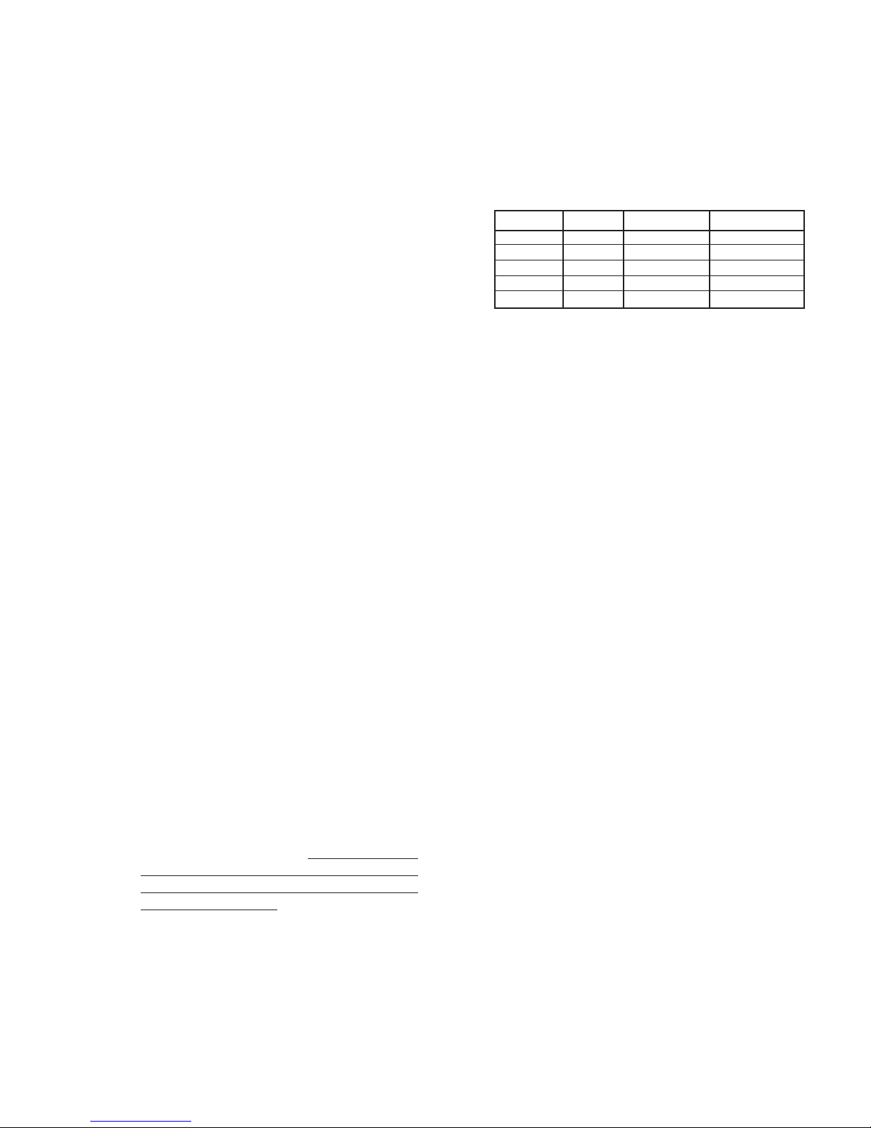
“prongs” as in di cat ed in the following di a gram.
If either of the below di men sions are exceeded
by 1/8" (3mm), re place rocker arm (14).
18. Place diaphragm spacer (41) over pusher
plate and stud. Place body spacer (42) over
outer perimeter of diaphragm(s) (20).
19. Install remaining quan ti ty of diaphragm(s) (20)
over pusher plate and stud (13).
20. Place O-ring (50) over push er plate and stud
(13).
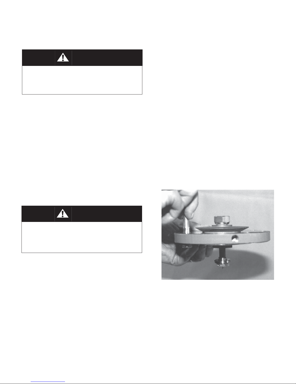
21. Inspect pressure plate (3) to ensure no
de for ma tion due to over-pressurization.
If de formed, bent, or otherwise distorted,
replace.
22. Ensuring that the curved outer rim side of the
pressure plate (3) is down, place the pressure
5
Valve Size
DIM MAT'L 1/2" (DN15) 3/4" (DN20) 1" (DN25)
A BRZ 7/8" 22 mm 1-5/32" 29 mm 1-7/16" 37 mm
B BRZ 5/8" 16 mm 25/32" 20 mm 3/4" 20 mm
A SST 13/16" 21 mm 1-1/16" 27 mm 1-7/16" 37 mm
B SST 9/16" 14 mm 23/32" 18 mm 3/4" 20 mm
DIM MAT'L 1-1/4" (DN32) 1-1/2" (DN40) 2" (DN 50)
A BRZ 1-13/16" 46 mm 1-25/32" 45 mm 2-3/16" 56 mm
B BRZ 29/32" 23 mm 7/8" 22 mm 29/32" 23 mm
A SST 1-1/2" 38 mm 1-25/32" 45 mm 2-5/32' 55 mm
B SST 11/16" 17 mm 7/8" 22 mm 29/32" 23 mm
IOM-1000HP-Dif fer en tial
25. Check rocker arm shaft (17) for wear and
straightness. Replace if damaged. Reinstall
in body (1) through rocker arm (14). Apply
thread sealant to the rocker arm shaft (17)
threads prior to tightening. Make sure that the
rocker arm shaft (17) enters the support slot
opposite the threaded opening, and does not
align crook ed and re strained from full thread
engagement of the rocker arm shaft (17).
Make sure that the rocker arm (14) prongs
that straddle the piston (24) hold the piston
collar (23) against the piston (24); do not allow
the rocker arm (14) prongs to push directly on
the piston (24).
26. Install a new di a phragm gas ket (19).
Com po si tion (soft) diaphragms require no
di a phragm gasket. NOTE: Use only gaskets
man u fac tured by Cashco, Inc., that are of the
same material as those originally supplied.
Sub sti tu tion may cause im prop er gas ket
com pres sion. It may also adversely change
the di a phragm setting, which will affect the
unit’s per for mance, i.e. Option 1000-45, nonas bes tos construction utilizes special gaskets.
30. Aligning the matchmarks, place spring
cham ber (2) over the above stacked parts.
Install all bolts (8), nuts (9) and nameplate (28)
by hand tightening. Tighten bolting (8 and 9)
in a cross pattern that allows spring chamber
(2) to be pulled down evenly. Recommended
torques are as follows.
Body Size Bolt Size Metal Diaph 1 Comp Diaph
1/2" 3/8"-24 25 ft-lb 25 ft-lb
3/4" 7/16"-20 30 ft-lb 30 ft-lb
1"–1-1/4" 1/2"-20 35 ft-lb 35 ft-lb
1-1/2" 9/16"-18 45 ft-lb 45 ft-lb
2" 5/8"-18 45 ft-lb 45 ft-lb
1
Minimum recommended torque regardless of gasket
ma te ri als. Some gasket materials may re quire higher
bolt torques to obtain adequate seal.
2
Gasket material may “set” with time; a recheck of
torques should be made if the unit has been stored
on the shelf for over 30 days.
NOTE: Never replace bolting (8 and 9) with just
any bolting. Bolt heads and nuts are marked
with spec i fi ca tion identification mark ings. Use
only proper grades as re place ments.
2
27. Using small gauge wire approximately 18"
(457 mm) long, form a hook and place the
hook over one prong of the rocker arm (14),
and rotate the rocker arm (14) up until slack
is removed in the mechanism. Secure the
wire through a body (1) flange bolt hole on
the outlet side of the regulator.
28. Firmly holding the outer perimeter, take the
di a phragm subassembly (Step 8) and lower
it down into the body (1) cavity off-center
ap prox i mate ly 3/4"–1" (20–25 mm) and
towards the inlet side of the regulator. When
fully low ered, slide the diaphragm subassembly
hor i zon tal ly towards the regulator outlet. The
wire of Step 27. should hold the rocker (14) up
to allow en gag ing of the pusher plate and stud
(13) (with stud nut (10) and stud collar (16)),
so the rocker arm (14) prongs rest directly
on the stud collar. NOTE: DO NOT ALLOW
THE ROCKER ARM (14) PRONGS TO GET
BE TWEEN THE STUD NUT (10) AND THE
STUD COL LAR (16). Pull firmly to remove
wire holding rocker arm (14) up.
29. Align diaphragm(s) (20) bolt holes with body (1)
flange bolt holes. Install new diaphragm gasket
(19) on top of diaphragm(s) (20). Vi su al ly
center range spring (27) on to pressure plate
(3), place spring button (4) on top of range
spring (27).
31. Reinstall adjusting screw (6) with sealing
lock nut (7); install new closing cap gasket
(32); install closing cap (31).
32. Pressurizing the body (1) and spring chamber
(2) to the same level, soap solution test around
bolting (8 and 9), body (1), spring chamber
(2) flanges, closing cap (31) and cylinder
(21) - to body (1) joint for leakage. Use 100
psig min i mum inlet pressure to leak test.
Actual service con di tions should be used if
in excess of the minimum condition. (NOTE:
Do not pres sur ize spring chamber without
equal or greater pressure in body registering
on diaphragm(s) (20) underneath side.)
C. Diaphragm Setting Adjustment:
1. In the previous “Sub-Section B., Diaphragm
Re place ment”, care was taken to prevent
removal of the stud collar (16) and stud nut
(10). Location of the stud nut (10) is a critical
adjustment for a Model 1000 regulator.
2. Not removing the stud nut (10) will provide
per for mance equal to original factory
per for mance when diaphragm(s) (20)
is replaced with like diaphragm(s) (20);
however, if the stud nut (10) is removed, or
a switch is made from metal to composition
(soft) diaphragm(s) (20), or vice versa, the
diaphragm setting should be checked.
6
IOM-1000HP-Dif fer en tial
 Loading...