


User Manual
HB4056-01(EN)
May 2015 |
Page 1 of 51 |

Thank you for purchasing the Casella dBadge2 Personal Noise Dosimeter. We hope that you will be pleased with it and the service that you receive from us and our distributors. If you do have any queries, concerns or problems, please do not hesitate to contact us.
Casella prides itself on providing precision instrumentation since 1799, supplying eminent figures including Darwin and Livingstone. A lot has changed in our 200+ year history but what does remain is our commitment to reliable, trustworthy and credible solutions.
For more information or to find out more about Casella and our products, please visit our website at: http://www.casellasolutions.com
UK Office
Casella
Regent House
Wolseley Road
Kempston
Bedford
MK42 7JY
Tel: +44 (0)1234 844100
Email: info@casellasolutions.com
United States |
China |
India |
Casella Inc. |
Ideal Industries China |
Ideal Industries India PVT Ltd |
415 Lawrence Bell Drive |
No. 61, Lane 1000 |
229-230 Spazedge |
Unit 4 |
Zhangheng Road |
Tower B, Sohna Road, Sector 47 |
Buffalo |
Pudong District |
Gurgaon 122001 |
NY 14221 |
Shanghai 201203 |
Haryana |
USA |
China |
India |
Phone: +1 (716) 2763040 |
Phone: +86 21 31263188 |
Phone: +91 124 4495100 |
Email: info@casellausa.com |
Email: info@casellasolutions.cn |
Email: Casella.Sales@ideal-industries.in |
May 2015 |
Page 2 of 51 |
1.Introduction
Noise induced hearing loss (NIHL) remains one of the world’s leading occupational diseases and it has been estimated that 16% of global hearing loss is due to occupational noise exposure. It is acute in the mining, construction, oil & gas sectors but also in a wide variety of industrial manufacturing and other commercial activities where the cumulative effects of excessive noise exposure could lead to this avoidable disease.
Noise exposure measurements using a personal noise dosimeter such as dBadge2 is a recognised method of making an exposure assessment as required by regulations and/or standards such as CFR 1910.95 Occupational noise exposure (USA), ISO9612:2009 Acoustics – Determination of occupational noise exposure – Engineering method, HSE Document L108 Controlling Noise at Work – Guidance on Regulations.
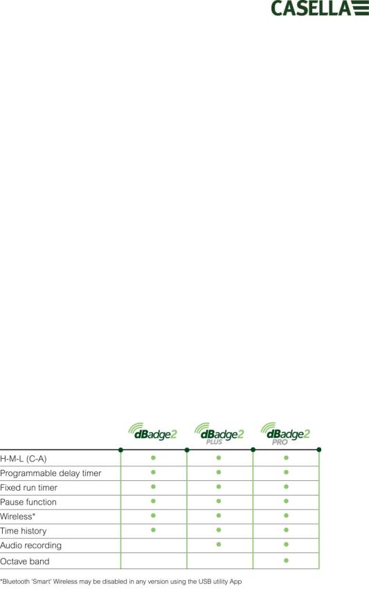
The original dBadge proved an invaluable tool in monitoring personal exposure but dBadge2 is the next generation, taking all of those features and usability and building on them; a true evolution. New features of the dBadge2 include:
Full colour display with colour-coded screens and alarms
Bluetooth® 4.0 wireless connectivity
Airwave App for mobile devices such as smartphones & tablets
Multiple simulated dosimeters (termed D1, D2 & D3)
Motion sensor
1 second time history profiling
Pause function
Recording of audio events (Plus & Pro models)
Real-time octave band frequency analysis (Pro model only)
USB download via Docking Station (and combined charger)
Updated & simplified Plug-in for Casella Insight data management software
The models and other key features of the dBadge2 range are listed below:
The addition of Bluetooth® 4.0 wireless connectivity and the supporting Airwave App enables remote control and monitoring of the instrument’s status such as battery usage, memory capacity and measurement progress without having to disturb the worker. This added confidence in the measurement minimises the likelihood of having to repeat a survey due to potentially flawed data and therefore maximises your productivity.
May 2015 |
Page 3 of 51 |

Personal noise exposure measurement can be confusing given the plethora of parameters available and the combination required to meet different standards and regulations but the dBadge2 has been specifically designed to simplify the process. Like its iconic predecessor, the dBadge2 concept is to capture every possible noise exposure related parameter during a measurement run and make it available for subsequent download and analysis. The user has only to choose the most relevant parameters to display on the screen.
The dBadge2 thus uses a ‘multiple simulated dosimeter’ concept to display noise exposure values according to these differing standards and regulations. The ‘simulated dosimeters’ are referred to as D1, D2 and D3 throughout this user manual and they define the measurement parameters that are displayed on screen.
The primary dosimeter (D1) provides any LAVG or LEQ based noise dose parameter plus a comprehensive set of related values. LEQ based noise exposure assessment e.g. to European standards, will typically only ever require the D1 dosimeter meaning D2 and D3 may be switched off in the configuration menu available on power up.
Dosimeters D2 and D3 allow the display of additional LAVG based noise dose values based on combinations of Threshold (T), Criterion (C) and Exchange rate (Q factor). As an example, a US customer may wish to simultaneously compare noise exposure data based upon the OSHA Hearing Conservation (HC), OSHA Personal Exposure Limit (PEL) and ACGIH requirements.
A user defined custom set up is also available for those who have their own internal standards that may exceed the exposure requirements laid down by regulations. This custom set up is available from Casella Insight.
It should be noted that for every measurement run, the dBadge2 records a comprehensive data set which means that you can retrospectively analyse the results within Casella Insight, regardless of what was displayed on the instrument in D1, D2 or D3.
May 2015 |
Page 4 of 51 |
2.Safety and Warnings
This product is not approved for intrinsically safe operation and must not be used within hazardous areas.
The dBadge2 contains no user serviceable parts. DO NOT open the product case, this will invalidate the warranty.
Repair and battery replacement must be carried out by authorised service personnel only.
Use only the recommended CEL-252 microphone and when in normal use ensure you always fit the windscreen. Only screw the microphone on ‘finger tight’ and do not use pliers to remove it should it become overtightened.
Under no circumstances should this equipment be cleaned using a solvent based cleaner.
When Bluetooth® is enabled, care must be taken to avoid interference with sensitive equipment such as in medical, aviation or safety critical environments.
May 2015 |
Page 5 of 51 |

3.Contents
Table of Contents
1. |
|
Introduction ....................................................................................................................................... |
3 |
2. |
|
Safety and Warnings .......................................................................................................................... |
5 |
3. |
|
Contents............................................................................................................................................. |
6 |
4. |
Typical Steps in a Noise Assessment.................................................................................................. |
7 |
|
5. |
Getting to know your instrument and accessories............................................................................ |
8 |
|
6. |
|
Using the dBadge2 ........................................................................................................................... |
12 |
7. |
|
Configuring the dBadge2 ................................................................................................................. |
20 |
8. |
|
Visual Alarm Warnings..................................................................................................................... |
26 |
9. |
|
Motion sensing ................................................................................................................................ |
27 |
10. |
Airwave Application................................................................................................................... |
28 |
|
11. |
Download Utility .......................................................................................................................... |
31 |
|
12. |
Casella Insight Data Management Software................................................................................ |
32 |
|
13. |
User Interface Diagrams .............................................................................................................. |
33 |
|
14. |
Technical Specifications ............................................................................................................... |
35 |
|
15. |
Glossary of Terms......................................................................................................................... |
39 |
|
16. |
Projected and Normalised Noise Measurements........................................................................ |
41 |
|
17. |
Noise Measurements – A Simple Analogy ................................................................................... |
44 |
|
18. |
Examples of Possible Measurement Scenarios............................................................................ |
45 |
|
19. |
Fault Finding & Diagnostics.......................................................................................................... |
49 |
|
20. |
Declarations ................................................................................................................................. |
50 |
|
May 2015 |
Page 6 of 51 |

4.Typical Steps in a Noise Assessment
May 2015 |
Page 7 of 51 |
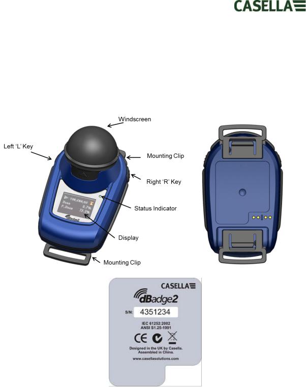
5.Getting to know your instrument and accessories
When delivered, dBadge2 will have its microphone, windscreen and mounting clips already assembled. The following spares are available; a replacement pack of 5 Windscreens (part number DB2WS) and 5 pairs of clips (part number DB2CLIPS).
The dBadge serial number is located on the rear label and should be quoted in any communication with Technical Support or Service.
If purchased as a complete measuring kit it will also come supplied with a CEL-120/2 Acoustic calibrator & 2 off AAA batteries, combined Docking Station & charger, PC18 Universal Mains power supply, CMC51 USB cable, Casella Insight data management software (supplied on a memory stick) and kit case suitable for up to 10 dBadge2 instruments and 3 Docking Stations.
The Airwave App and download utility are available for download from the Support section of the Casella website as detailed in Sections 10 and 12 of this handbook respectively.
May 2015 |
Page 8 of 51 |
5.1Mounting the dBadge2
The recommended location for mounting a personal noise exposure meter is normally in a position close to the ear (10-15cm). The dBadge2 should therefore be mounted on the apex of the shoulder to avoid reflections from the head which might otherwise affect the measurements. Consult your local Legislation and Standards for more information.
Upon delivery, the dBadge2 will be fitted with crocodile-style mounting clips on flexible webbing to aid positioning. The clip assembly simply snaps in place but are designed to ‘fail safe' i.e. the tab on the black plastic part that mates with the main body of the instrument has to be lifted (pulled) to remove it (in normal use it would tend to be pressed/pushed).
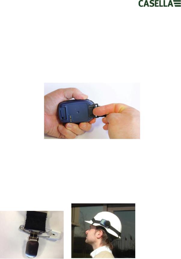
Should the clip assembly require replacement, hold the dBadge2 with the back uppermost in one hand and with the other hand simultaneously lift the tab with a finger whilst pulling the clip away from the dBadge2 body. There is a knack to this operation to deter tampering. A pack of spare clips (5 pairs) is available (part number DB2CLIPS). When refitting the clip assembly ensure that the tab is locked by pushing it into place and pull on the clip assembly to check that it is secured.
A pin attachment (part number CL63) is also available which can be secured directly via the clip or be attached to the webbing.
It is also possible to attach the dBadge2 to a harness (part number D8147/Z) by feeding the harness though the blank webbing buckle clip fittings (part number 207073B). For any existing harness that an employee might already be wearing, use the pin attachment. In addition, the dBadge2 may be mounted to most hard hats using the mounting kit (part number CEL-6354)
May 2015 |
Page 9 of 51 |
and safety pins. This consists of a strap with four hooks which loop over the rim of the hard hat.
5.2The Microphone & Windscreen
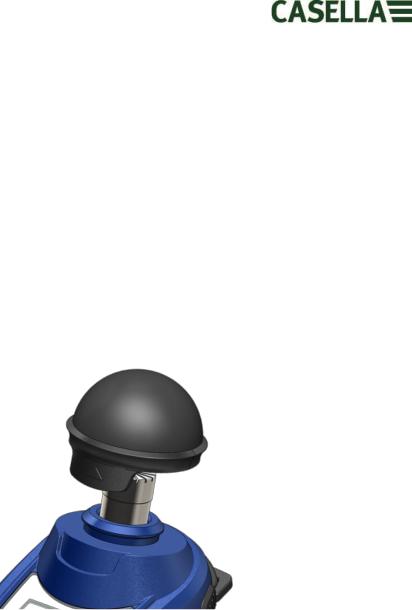
During use, it is essential that the dBadge2 is fitted with the Windscreen (part number 207069B, supplied). The Windscreen protects the microphone from potential erroneous results due to air movement passing over it but also helps to protect from dust ingress, moisture or minor impact damage. It will not normally be necessary to remove the microphone but to do so unscrew anticlockwise. When refitting take care since it has a fine thread and do not overtighten; finger tight is sufficient.
To calibrate the dBadge2 it is necessary to remove the Windscreen to expose the microphone. Grip the black plastic body and pull in the direction of the arrow indicated on the tab of the Windscreen. Do not pull on the foam which may become detached and hence need replacing (replacement pack of 5, part number DB2WS)
Following calibration (see Section 6.2) refit the Windscreen by aligning the tab with the recess in the main body of the dBadge2. An audible “click” confirms that it is securely in place.
May 2015 |
Page 10 of 51 |
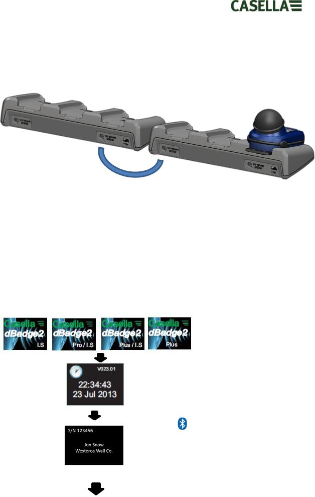
5.3.1Linking Docking Stations Together
A master docking station can be linked to another via an interconnect cable (C6359/0.2 supplied wth part 207078B/EXT). Up to 3 docking stations can be linked to the master as shown below enabling up to 12 dBadge2s to be charged simultaneously from one PC18.
6.Using the dBadge2
6.1Switching on the dBadge2
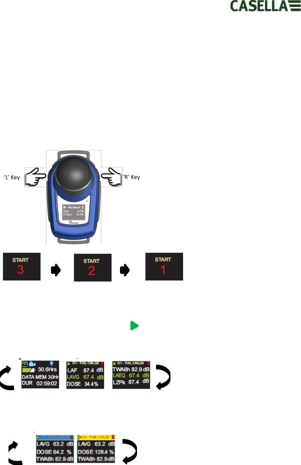
Press the left ‘L’ key to turn the dBadge2 on and a start-up sequence will commence.
If you wish to configure the dBadge2 manually then this must be done at this point. Please refer to Section 7 for further details.
This initial start-up screen displays the dBadge2 model number, a second screen then displays the time and date and firmware version (e.g. V1.04) and a third screen displays the serial number of the dBadge2 with two lines of user-defined text. This may be up to 32 characters and is input via Casella Insight data management software.
|
The screen then defaults to the main |
|
|
|
dashboard screens which either auto or |
|
|
|
manually scroll depending whether the |
|
|
|
Autoscroll feature has been enabled. |
|
|
|
Please refer to Section 7.14. |
|
|
|
The |
symbol shows that Bluetooth® |
|
|
is enabled. |
|
|
|
Additional symbols appear in the Plus |
|
|
|
and Pro models and denotes ‘Audio |
|
|
|
Record’ and/or ‘Octave’ modes are |
|
|
. |
enabled. |
|
|
|
|
|
|
May 2015 |
|
Page 12 of 51 |
|
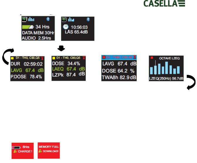
If the Autoscroll feature has been disabled (see Section 7.14) pressing the right ‘R’ key will scroll through the available results from the last run depending upon how the dBadge2 was configured e.g. octave band results are shown above, which are only available on the Pro model and if selected in the configuration menu (see Section 7.8).
6.1.1Error Messages At Power Up
If there are any error messages they will appear after the initial start-up screens:
Warning messages appear when there is less than 9 hours charge or less than 9 hours memory (based on standard usage). Press any key to return to the default screen or alternatively these error messages will time-out after 30 seconds. Please either re-charge, download and/or erase data as required before continuing with a new measurement run.
6.2Calibrating the dBadge2
It is best practice (and often mandatory) to field calibrate each dBadge2 both before and after use. The dBadge2 records calibration levels and times which can be viewed later in Casella Insight data management software which will also allow the target calibration level to be set as shown on the calibrator’s own calibration certificate, nominally 114.0dB.
May 2015 |
Page 13 of 51 |
Note: the dBadge2 will not enter the calibration mode if a measurement run is taking place. If a run is in progress, stop the run according to Section 6.5.
The windscreen should be removed prior to calibration. Please refer to Section 5.2
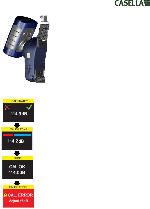
Push the CEL-120/2 (or other approved) acoustic calibrator over the microphone as shown. The calibrator should be pushed on without twisting (which may loosen or overtighten the microphone) until fully home and switched on.
The dBadge2 will automatically recognise a 1kHz calibration tone and enter the calibration mode.
Press the right ‘R’ key to confirm you wish to calibrate, or the left ‘L’ key to cancel the operation. It will take a few seconds to automatically calibrate to 114 dB during which time a progress bar is displayed as shown.
Once the dBadge2 has successfully calibrated the ‘CAL OK’ message will appear.
In the unlikely event an error message is displayed please refer to the
‘Troubleshooting’ section.
The dBadge2 is ready to take a measurement once the calibrator has been removed and the Windscreen re-fitted.
You may need to consult local regulations or standards if the ‘before’ and ‘after’ calibration values differ by more than (typically) +/- 0.5dB e.g. section 12.2 of ISO 9612:2009 suggests that the measurement is re-taken.
6.3Starting a Measurement Run
Before starting a measurement run, ensure the Windscreen is fitted according to Section 5.2 and ensure there is sufficient battery life and memory by looking at the default screen shown in Section 6.1.
May 2015 |
Page 14 of 51 |
If necessary, charge the dBadge2 as described in Section 5.3. If the memory is full either clear it as described in Section 7.17 or download the data to Casella Insight data management software.
Note: if the battery or memory available is less than one hour, the run will not start.
Regardless of whether D1, D2 or D3 is selected for display purposes, ALL parameters are calculated and stored simultaneously and can be viewed via Casella Insight data management software.
Timers are also available to automatically start and stop a measurement run or halt a run after a fixed period. These options may be selected in the Configuration menu, see Section 7.15.
To manually start a measurement run, press and hold both the left ‘L’ and the right ‘R’ keys down together which will initiate a 3 second countdown as shown.
The keys must remain depressed during the countdown for the measurement run to begin; releasing during the 3-2-1 countdown will cease the operation.
Once the measurement has begun, the ‘play’ symbol will appear in the top left of the screen. The display will cycle between the following screens if the Autoscroll mode has been selected in the configuration menu (see Section 7) or may be scrolled manually by pressing either the left ‘L’ or right ‘R’ key:
If Dosimeters D2 and D3 are enabled, the following screens will also be displayed;
D1 is the primary dosimeter which reports selected dose values plus other noise parameters (peak, max etc.) D2 and D3 offer additional. The header bar for D1 measurements is the background screen colour, D2 has a blue header bar and D3, a yellow header bar.
May 2015 |
Page 15 of 51 |
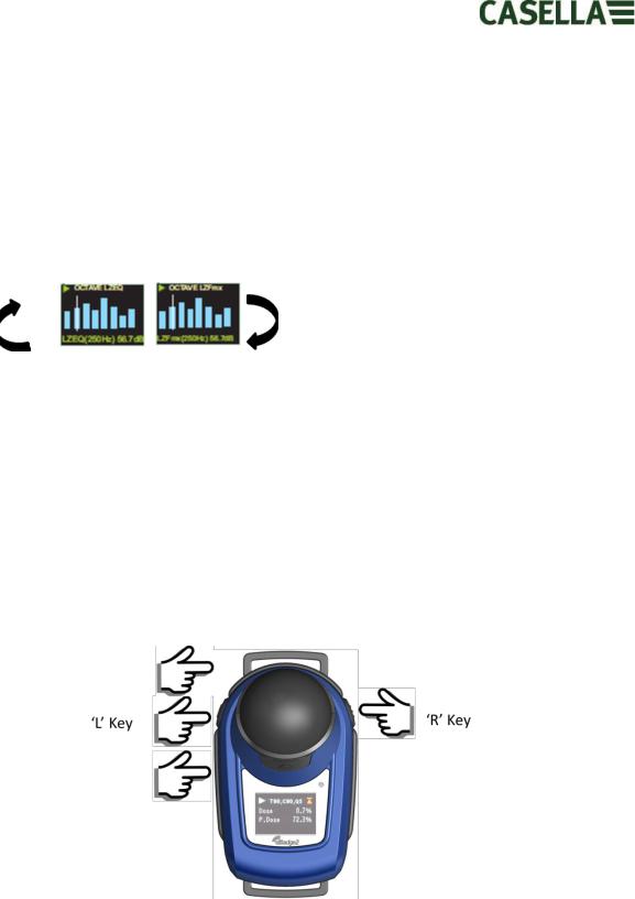
If the Octave mode has been enabled in the configuration menu (applicable to the dBadge2 Pro model only, see Section 7.8 ) subsequent presses of the right ‘R’ key will display the following screens and a vertical cursor will appear at the extreme right of the screen (and display the 8KHz band value). The left ‘L’ key will move the cursor to the left and display the other octave band values. With the cursor at the lowest 32Hz band, subsequent presses of the left ‘L’ key will scroll to the previous screen and similarly with the cursor on the 8KHz band, pressing the right ‘R’ key will scroll to the next screen.
If results are required to be pre A-weighted, this can be enabled via Casella Insight data management software.
6.4Locking and Unlocking the Keys
It is recommended that the dBadge2 is locked during a run to prevent the wearer tampering and this can be done automatically upon the start of a run having first selected ‘Auto Lock’ in the configuration menu (see Section 7.12) or manually as follows.
Press and hold the right ‘R’ key for 2 seconds then press the left ‘L’ key 3 times in quick succession as shown
A  padlock symbol will be displayed to indicate that the dBadge2 is locked and will not display any measured data.
May 2015 |
Page 16 of 51 |
 Loading...