


Professional Water Treatment Products
OperationManualforSystemsUsingthe
CASCADIAN® 7G2xAdvancedMicroprocessor–BasedGeneration2SmartControls
7G2b Smart Filter Controllers for CASCADIAN® Filter Systems Including:
AcidFIX™ pH Raising Systems ArsenicTRAP™ Arsenic Removal System
OxiMax™ Salt Free Iron, Manganese and H2S Filter SuperPOLISH™ Activated Carbon Polishing Filter SuperTRAP® Sediment and Particle Filter
7G2i Smart Ion Exchange Controllers with AVR Active Variable Reserve for
CASCADIAN® Automatic Softener and Ion Exchange Filter Systems Including:
CHTC™ Combined Hardness, Tannins & Color FluorideTRAP™ Fluoride Removal NitrateTRAP™ Nitrate Removal Filter OrganicTRAP™ Total Organics and Tannins Pinnacle™ Automatic Softener
IMPORTANT:
Fill in pertinent information on page 3 for future reference. The information, specifications and illustrations in this manual are based on the latest information available at the time of printing. CASCADIAN® reserves the right to make changes at any time without notice.
www.CascadianWater.com
CASCADIAN® Professional Water Treatment Products |
|
Operation Manual for systems using the 7G2b and 7G2i Generation 2 Controls |
|
Table of Contents |
|
Major Components Diagram .......................................................................................................................... |
3 |
Typical Installation Sequence ........................................................................................................................ |
4 |
Job Specifications Sheet ............................................................................................................................... |
5 |
Residential Installation Checklist .................................................................................................................... |
6 |
Factory Programming ............................................................................................................................... |
6 |
Additional Requirements ........................................................................................................................... |
6 |
Basic Installation and Start-up Procedures....................................................................................................... |
7 |
7G2x Control Operation and Settings.............................................................................................................. |
9 |
Basic Control Description........................................................................................................................... |
9 |
Control Display Panel................................................................................................................................ |
9 |
Control Valve / Timer Operation................................................................................................................... |
10 |
Setting the Time of Day .......................................................................................................................... |
10 |
Manually Initiating a Regeneration............................................................................................................ |
10 |
User Programming Mode ......................................................................................................................... |
11 |
Diagnostic Programming Mode ................................................................................................................. |
12 |
7G2b Master Programming Mode: Recommended for trained CASCADIAN® professional dealers only.................. |
14 |
7G2i Master Programming Mode: Recommended for trained CASCADIAN® professional dealers only................... |
16 |
Power Head Assembly Parts Diagram............................................................................................................ |
18 |
Power Head Assembly Parts List:.............................................................................................................. |
18 |
Valve Assembly Parts Diagram..................................................................................................................... |
19 |
Valve Assembly Parts List........................................................................................................................ |
19 |
Bypass Assembly ....................................................................................................................................... |
20 |
Bypass Assembly Parts List...................................................................................................................... |
21 |
Optional Elbow Kit (2 required). ................................................................................................................... |
21 |
Elbow Kit parts list ................................................................................................................................. |
21 |
2310 Safety Brine Valve Diagram................................................................................................................. |
22 |
2310 Safety Brine Valve Parts List ............................................................................................................ |
22 |
Dimensional Drawings ................................................................................................................................ |
23 |
General Service Hints For Metered Controls ................................................................................................... |
24 |
Auxiliary Relay and Chemical Pump Output Relay: .......................................................................................... |
24 |
Troubleshooting......................................................................................................................................... |
25 |
Error Codes .............................................................................................................................................. |
26 |
“Limited” CASCADIAN® Water Treatment Equipment Warranty ........................................................................ |
28 |
IMPORTANT PLEASE READ:
•The information, specifications and illustrations in this manual are based on the latest information available at the time of printing. O3 Water Systems reserves the right to make changes at any time without notice.
•This manual is intended as a guide for service of the valve only. System installation requires information from a number of suppliers not known at the time of manufacture. This product should be installed by an Authorized CASCADIAN® Dealer or plumbing professional trained in water treatment system installations.
•This unit is designed to be installed on potable water systems only. If installation requires treatment of irrigation water please consult your water treatment professional.
•This product must be installed in compliance with all state and municipal plumbing and electrical codes.
•Correct and constant voltage must be supplied to the control valve to maintain proper function. A surge protector is recommended – an Uninterruptable Power Supply (UPS) is preferred.
•If daytime operating pressure exceeds 80 psi, nighttime pressures may exceed pressure limits. A pressure reducing valve must be installed.
•Do not install the unit where temperatures may drop below 34°F or above 110°F.
•Do not place the unit in direct sunlight. Black units will absorb radiant heat increasing internal temperatures.
•Do not strike the valve or any of the components.
•Warranty of this product extends to manufacturing defects. No warranty is made as to Fitness for a particular purpose. Misapplication of this product may result in failure to properly condition water, or damage to product.
• A prefilter should be used on installations in which free solids are present.
•In some applications local municipalities treat water with Chloramines. High Chloramine levels may damage valve components.
• The term 7G2x is used when referring to both the 7G2b and 7G2i controls.
Page 2 |
CASCADIAN® 7G2x_Manual.docx |
www.CascadianWater.com |
CASCADIAN® Professional Water Treatment Products
Operation Manual for systems using the 7G2b and 7G2i Generation 2 Controls
CASCADIAN® Automatic Solutions
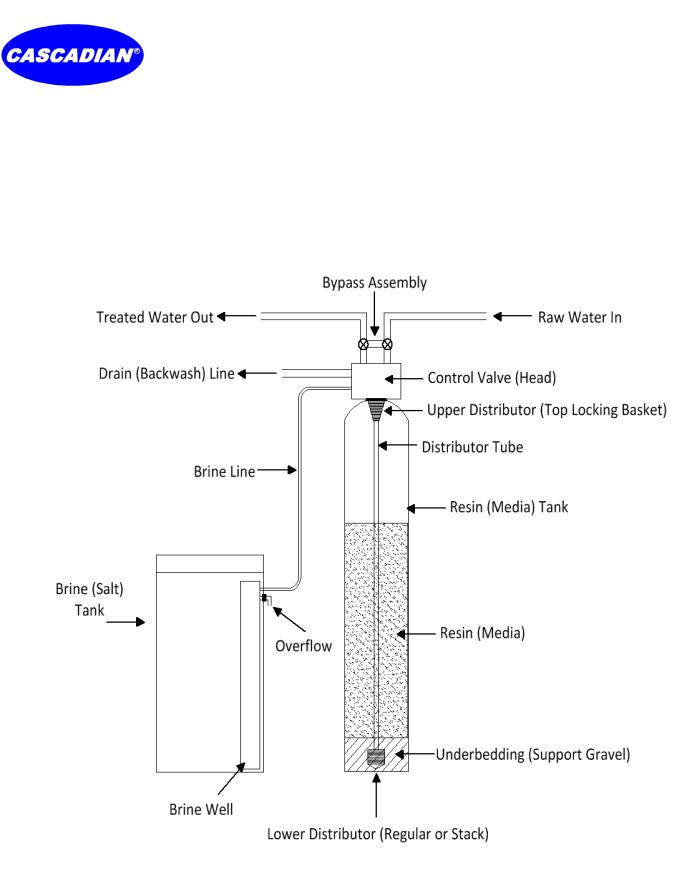
Major Components Diagram
*Not all components included with every system
Page 3 |
CASCADIAN® 7G2x_Manual.docx |
www.CascadianWater.com |

CASCADIAN® Professional Water Treatment Products
Operation Manual for systems using the 7G2b and 7G2i Generation 2 Controls
Typical Installation Sequence
Page 4 |
CASCADIAN® 7G2x_Manual.docx |
www.CascadianWater.com |

CASCADIAN® Professional Water Treatment Products
Operation Manual for systems using the 7G2b and 7G2i Generation 2 Controls
Job Specifications Sheet
Circle and/or Fill in the Appropriate Data for Future Reference.
Job Number ___________________________________________
CASCADIAN® Part Number _______________________________
CASCADIAN® Serial Number (located on valve body) __________________________
Water Test Number ____________________________________________
Maximum Flow Capacity of Unit ________________________
7G2x Valve used in this application: 7G2b or 7G2i |
|
|
|
|
|
|
7G2b: |
7G2i: |
|
For regenerating CASCADIAN® Generation 2 backwashing |
For regenerating CASCADIAN® Generation 2 Pinnacle |
|
filter systems including the AcidFIX™, ArsenicTRAP™, |
Softeners and Ion Exchange filter systems including CHTC™, |
|
OxiMax™, SuperPOLISH™ and SuperTRAP®. |
such as the FluorideTRAP™, NitrateTRAP™, and OrganicTRAP™. |
Valve Programming (quick site specific information)
System Type: Meter Immediate / Time Clock Delayed / Volume Override Delayed / Volume Override Immediate / Meter Delayed Weekly Reserve / Meter Delayed Variable Reserve / Meter Delayed Fixed Reserve
Treated Water Capacity _____________________________________ (Gallons) Regeneration Volume Override ________________________________ (Gallons) Safety Factor % ________________________________
Regeneration Day Override ___________________________________ (Maximum Days Between Backwashes)
Regeneration Time _____________________________________ (A.M.) (P.M.) NOTE: When treatment solution requires multiple filter and / or softener units be sure to stagger backwash / regeneration times so only one unit backwashes or regenerates at any one time.
7G2i Timer Program Settings: |
7G2b Timer Program Settings: |
|||
1. |
Cycle 1 Backwash: ____________________Minutes |
6. |
Cycle 1 Backwash: ____________________Minutes |
|
2. |
Cycle 2 |
Brine Draw: ___________________Minutes |
7. |
Cycle 2 Rapid Rinse: ___________________Minutes |
3. |
Cycle 3 |
2nd Backwash: _________________Minutes |
|
|
4. |
Cycle 4 |
Rapid Rinse: ___________________Minutes |
|
|
5. |
Cycle 5 |
Brine Tank Fill: _________________Minutes |
|
|
Auxiliary Relay: Enabled or Disabled
Auxiliary Relay Output Start 1: __ __ : __ __ : __ __ Auxiliary Relay Output End 1: __ __ : __ __ : __ __ (times from beginning of regeneration cycle)
Auxiliary Relay Output Start 2: __ __ : __ __ : __ __ Auxiliary Relay Output End 2: __ __ : __ __ : __ __ (times from beginning of service cycle)
Chemical Pump Output: Enabled or Disabled; CPO Aux Relay Volume ________ Gallons; CPO Aux Relay Time __ __ : __ __ : __ __
Flow Meter: 1.25” Turbine
Drain Line Flow Control: ___________________ gpm Notes:
Page 5 |
CASCADIAN® 7G2x_Manual.docx |
www.CascadianWater.com |
CASCADIAN® Professional Water Treatment Products
Operation Manual for systems using the 7G2b and 7G2i Generation 2 Controls
Residential Installation Checklist
1.Water Pressure and Temperatures
A minimum of 25 psi inlet water pressure is required for the 7G2x valve to operate effectively.
2.Electrical Facilities
a.An uninterrupted alternating current (A/C) supply is required. Current draw is 7 watts at 24 VAC.
b.Voltage supply 115 / 120 VAC, 60Hz unless otherwise specified.
c.Current supply is always hot and cannot be turned off with a switch, must be unswitched – always on..
d.It is recommended that a UPS (Uninterruptable Power Supply) be installed to protect the system electronics.
3.Existing Plumbing
Condition of existing plumbing should be free from lime, iron and bacteria buildup. Replace piping that has heavy lime and/or iron build up. Water test results may indicate additional treatment is required before or after this system. It is recommended irrigation and all outside taps be separated from the treated water stream.
4.Location of System and Drain
a.Locate the system on a hard level surface and as close as possible to a clean working drain. Connect according to local plumbing codes.
b.A vacuum relief valve is recommended.
c.Locate upstream of any hot water tank so a minimum of 10 feet of piping is between the unit outlet and hot water heater inlet.
d.In Well Water applications the unit is located after the pressure tank.
5.Bypass Valves
Always provide for the installation of a bypass valve if unit is not equipped with one.
CAUTION:
Minimum water pressure 25 psi.
Maximum water pressure 125 psi.
Minimum water temperature 34° F.
Maximum water temperature 110° F.
Ambient temperature 34° to 122° F
Disconnect all power sources before servicing.
Always operate with cover in place.
NOTE:
This product should be installed by qualified professional. An Authorized CASCADIAN® Solutions™ Dealer is recommended.
Comply with all plumbing codes when installing this product.
Comply with all electrical codes when installing this product.
WARNING:
The controller MUST be depressurized before removing any quick connection clips for servicing. Once pressurized the connectors must be unlocked before attempting to remove them.
Factory Programming
Your CASCADIAN® water treatment system has had the unit’s sequence of cycles, cycle times, salt dose, exchange capacity, day override, brine tank refill time and time of regeneration preset at the factory. A default is set for hardness. Should a reset be performed on a control please verify proper programming for your system.
Additional Requirements
The installer must:
1.Read and understand this guide.
2.Verify proper settings for specific installation (having water quality data ready) call for assistance with setting Volume Override, Day Override (preset to 7 days), Time of Regeneration (preset to 12:00 A.M. for 7G2b and 2:00 A.M. for 7G2i controls).
3.Set Time of Day.
4.Instruct owner as to required maintenance, how to adjust time of day and other adjustments as appropriate for the specific system.
5.Present owner with completed 7G2x Basic Operation Insert.
Page 6 |
CASCADIAN® 7G2x_Manual.docx |
www.CascadianWater.com |
CASCADIAN® Professional Water Treatment Products
Operation Manual for systems using the 7G2b and 7G2i Generation 2 Controls
Basic Installation and Start up Procedures
Installation Instructions
1.Prepare the Media Tank.
a.Place the Media tank where you want to install the system making sure the tank is plumb and on a firm base.
b.During cold weather warm the valve to room temperature before installing.
c.Perform all plumbing according to local plumbing codes. Drain line size should be the same as the drain line flow control. A vacuum relief valve is recommended.
d.If needed glue distributor basket to one end of the distributor tube.
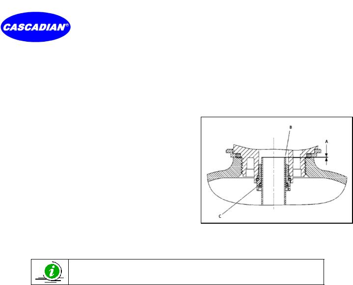
e.Place tube with basket into center of tank and if needed, cut the distributor tube flush with top of tank (A) and deburr the outside of the tube (B) after cutting.
f.Lubricate the distributor 0 ring seal (C) and tank 0 ring seal. Use only silicone based lubricant.
g.Temporarily block top opening of distributor tube to prevent media from entering the tube while filling tank.
h.Load media keeping distributor basket and tube centered in tank. When using multiple media be sure to load in the recommended order.
i.Remove temporary block from distributor tube.
2.Install 7G2x Control Valve and position Media Tank.
a.If a locking upper distributor basket is included with your system place and lock the distributor to the bottom of the valve.
b.Place the valve over the distributor tube and spin the valve onto the tank
ensuring the threads are not cross threaded. Rotate the valve freely without force until it comes to a stop. Rotate valve an additional ¼ to ½ turn. The valve is now properly tightened.
c.If needed, rotate or reposition the tank with unit to its final position.
NOTE:
All soldering MUST be done on any connections requiring soldering prior to connecting the main control. The main control will be damaged if it is connected at the time of soldering.
3.Connect Plumbing and electrical.
a.Make plumbing connections to Inlet, Outlet and drain fittings on valve assembly. A vacuum relief valve is recommended. Note: Teflon tape is the only sealant to be used on valve fittings.
b.If the buildings electrical system is grounded to the plumbing make certain ground is continuous after installation. Plumbing must be done in accordance with all applicable local codes.
c.Place unit Bypass into the Bypass Position (see page 21) and slowly turn on the main water supply and check for leaks.
d.Slowly open a cold treated water tap nearby and let water run a few minutes or until the system is free of foreign material resulting from the installation. Close the water tap when water runs clean.
e.Plug the valve into an approved un switched power source. NOTE: make all electrical connections according to codes.
4.Prepare and connect Brine Tank (7G2i controls only).
a.Make sure the floor is clean below the Brine (salt) Tank location and that it is level. Since salt must be periodically added to the brine tank it should be located where it is easily accessible.
b.Place approximately 1” of water above the grid plate. If a grid is not utilized, fill to the top of the Air Check (see page 8) in the salt tank. Do not add salt to the brine tank at this time.
c.Install the ⅜” O.D. Polyethylene tube from the brine line fi ng on the 7G2i Control Valve to the brine valve (see page 22) on in the brine tank.
d.An overflow drain line is recommended where a brine overflow could damage furnishings or the building structure. Your CASCADIAN® system is equipped with a brine tank safety valve which greatly reduces the chance of an accidental brine overflow. In the event of a malfunction an overflow line connection will direct the “overflow” to the drain instead of spilling on the floor where it could cause considerable damage. This connection is an elbow fitting on the side of the brine tank.
i.Attach a length of ½” I.D. tubing to the fitting and run to drain.
ii.Do Not elevate overflow line to more than 3” below the bottom of the fitting.
iii.Do Not connect this tube to the drain line of the control valve. Overflow line must be a direct separate line from fitting to drain.
iv.Allow an air gap.
Page 7 |
CASCADIAN® 7G2x_Manual.docx |
www.CascadianWater.com |
CASCADIAN® Professional Water Treatment Products
Operation Manual for systems using the 7G2b and 7G2i Generation 2 Controls
5.Bring the system online.
a.Manually cycle the 7G2i control valve to the Backwash Position (see page 10). Open the inlet side of the Bypass just enough to hear water flow and air escape the unit and let the water flow slowly into the media tank until the air is purged from the unit. After air is purged slowly open the Bypass inlet all the way.
b.7G2i Controls Only:
i.Manually step the valve to the Brine Draw position (see page 10), verify water is being drawn from the brine tank and allow the valve to draw water from the brine tank until it stops. NOTE: The air check will check at approximately the midpoint of the screened intake area.
ii.Manually step the valve past the 2nd Backwash and Rapid Rinse cycles to the Brine Tank Fill cycle (see page 10), verify water is being added to the brine tank and allow the valve to return to In Service automatically.
iii.With the valve In Service, check that there is at least 1" of water above the grid in the brine tank (if a grid is used) or to the top of the Air Check.
iv.Fill the brine tank with salt and place cover on tank. Solar salt in pellet form is recommended, DO NOT use rock salt.
6.Open the Bypass outlet and manually initiate a regeneration cycle.
a.Clean filter media: If your systems is a filter with the 7G2b control the media contains fines that must be backwashed out of the media, continue backwashing the unit until backwash water running to drain is clear. Gently tap the side of the tank while in backwash cycle just enough to vibrate the media. Caution: Tapping too hard may damage the media tank, a damaged tank do to excessive force will not be warranted. If tapping the side causes the backwash water turn color wait till it runs clear again and repeat this process until it does not turn color after tapping. This step is essential for proper installation and system function, it must not be skipped.
b.After a complete regeneration your CASCADIAN® softener / filter unit is now in service.
7.Inform owner about reading operating and display instructions. Point out that the clock may need to be re set if the power goes out and will need to be reset for changes in daylight savings time.
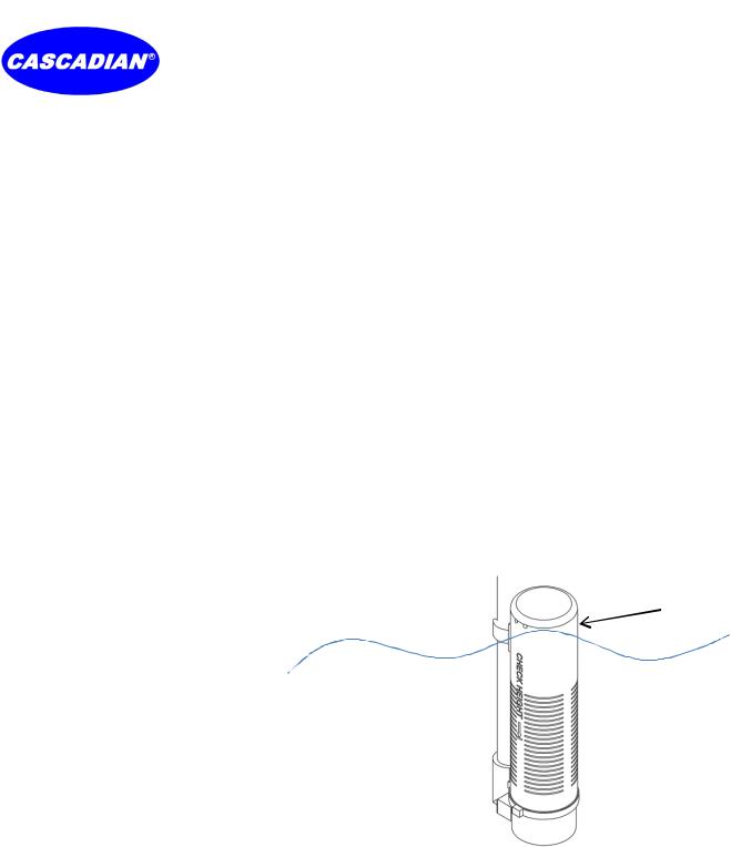
Water level at top of Air Check
Residential Air Check Valve
Page 8 |
CASCADIAN® 7G2x_Manual.docx |
www.CascadianWater.com |
CASCADIAN® Professional Water Treatment Products
Operation Manual for systems using the 7G2b and 7G2i Generation 2 Controls
7G2x Control Operation and Settings
NOTE:
The words Regeneration and Backwash may be used interchangeably to describe the sequence of events the 7G2x Control performs to periodically clean or recharge the treatment system.
Basic Control Description
The 7G2x Control is a Generation 2 Advanced, Microprocessor – Based, Metered, Smart Controller and the most efficient control available. The 7G2x regenerates or backwashes the system based on actual water quality and volume used resulting in lower volume of water used in the automatic cleaning process and a significantly reduce amount of salt use. The 7G2x Smart Controller is the most efficient water treatment system available.
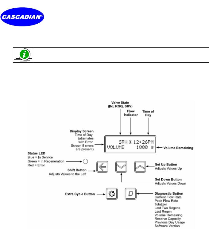
Control Display Panel
Parameter Display Codes:
Valve State:
INI (Initializing): INI will display on the screen for 30 to 45 seconds when initializing after a power failure reset or programming.
RGQ (Regeneration Queued): RGQ indicates that the reserve has been entered in a delayed system and regeneration has been queued. When in the main screen, press the Shift button to toggle service (SRV) with RGQ.
SRV (Service): SRV will display when the unit is in service.
LED Status Lights:
Blue LED: Illuminates while the unit is in service and no errors exist. The unit will always be in service unless a regeneration trigger has occurred green LED light will be displayed).
Green LED: Illuminates when the unit is in Regeneration mode, unless an error condition exists. Red LED: Illuminates when there is an error.
Flow Indicator: A rotating line (appearing as a rotating star shape) will display on the screen when treated water flow is going through the meter (does not meter water going to drain).
Page 9 |
CASCADIAN® 7G2x_Manual.docx |
www.CascadianWater.com |
 Loading...