

®
3
W-85 WALL CONTROL INSTALLATION
W-85 WALL CONTROL PREPARATION
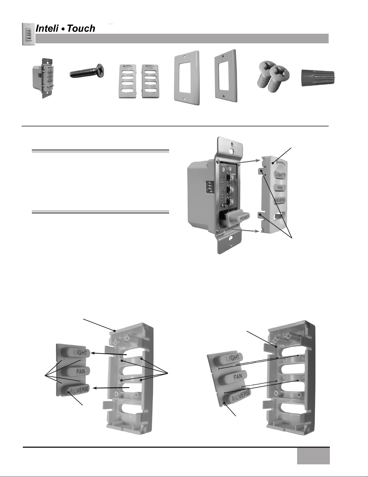
WALL CONTROL AND HARDWARE (not to scale)
Switch Mounting
Screws (2)
W-85
Wall Control
Prepare for W-85 Wall Control Bezel replacement
as follows:
Before installing the W-85 wall control you will need to
check and see if you will need to change the bezel on
the front of the wall control from WHITE to ALMOND.
If you are going to use white, skip these steps and go
to wall control installation starting on page 3. If you are
going to use the ALMOND bezel and wall plate you
will rst need to change the bezel on the front of the
switch before installing the switch in to the wall.
Switch Bezels
(1) White
(1) Almond
White Wall
Plate(1)
Almond Wall
Plate(1)
Wall Plate Screws
(2) White
(2) Almond
(4) Wire Cap
BEZEL
Step 16a. Locate the four (4) tabs holding the bezel to
the front of the switch, then press in on each tab one at
a time, removing the bezel as shown in Figure #1.
Step 16b. Locate the rubber key pad attached to
the four (4) locating pins as shown in Figure #2 and
remove rubber key pad from the WHITE bezel, also
as shown in Figure #2.
Step 16c. Reinstall the rubber key pad on to the
four (4) locating pins located on the almond bezel as
shown in Figure #3.
WHITE
BEZEL
LOCATING
PINS
HOLES(4)
BEZEL
TABS
Figure #1
ALMOND
BEZEL
LOCATING
PINS (4)
RUBBER KEY
PAD
Figure #2
RUBBER KEY
PAD
Figure #3
1
®
3
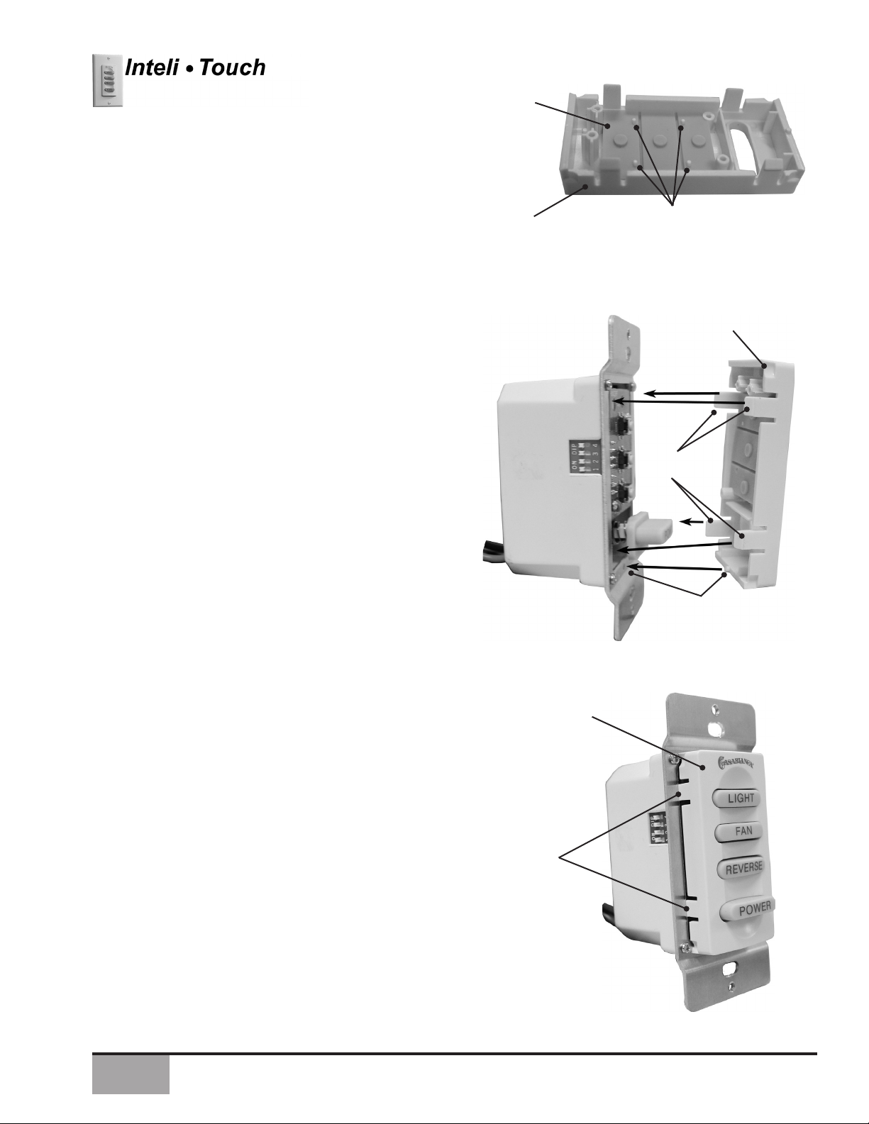
Prepare for W-85 Wall Control installation Continued
Step 16d. Before attaching the bezel back on to the
front of the switch, make sure that the rubber key
pad is attached to the locating pins on the bezel as
shown in Figure #4.
Step 16e. To attach the bezel back on to the front
of the switch you will need to align the four (4) tabs
on the bezel with the front of the wall control and by
gently pressing on both top and button of the bezel at
the same time, snap the bezel back on to the front of
the switch as shown in both gures #5 and #6.
RUBBER KEY
PAD
ALMOND
BEZEL
LOCATING
PINS
(4)
Figure #4
ALMOND
BEZEL
BEZEL
TABS
Step 16f. Check your work by pressing on the light,
fan, reverse and power buttons, making sure that the
buttons do not stick and that each switch functions
properly.
BEZEL
ALIGNMENT
PIN AND HOLE
Figure #5
ALMOND
BEZEL
BEZEL
TABS
2
Figure #2
®
3
W-85 CONTROL INSTALLATION
INSTALLING THE W-85 WALL CONTROL
NOTE: W-85 Wall Control should only be installed on Casablanca's Inteli-Touch® 3 fans with DOWNLIGHTS
ONLY.
The wall control installs in the same manner as an ordinary light switch, using an existing wall box and wiring. This
controller is designed to signal the fan microcomputer as well as perform normal switching operations. For this
reason the following precautions must be observed:
1. Use only the Casablanca W-85 wall control.
2. Do not use any additional control with your InteliTouch 3 fan (for example, dimmer, or fan speed
control).
3. Do not use more than one fan per wall control.
4. No other light xtures or electrical appliances may
be connected on the circuit controlled by the W-85
wall control.
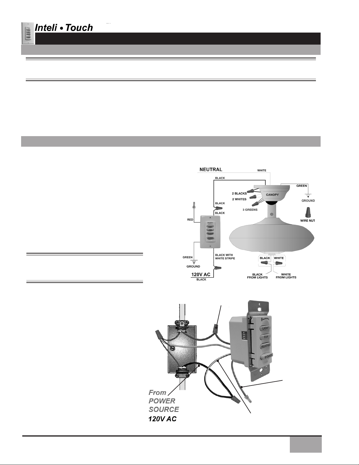
SINGLE W-85 INSTALLATION
CAUTION!
Ensure power is turned OFF at the breaker or fuse panel before starting installation.
W-85 is used to describe either white (-11) or almond nish.
If you have multiple Inteli-Touch 3 fans, refer to the section
"Changing Frequency Setting" on page 6.
1. Remove the screws and switch plate from the existing
switch box.
2. Remove the screws holding the switch in the switch
box.
3. Pull the existing switch from the switch box to expose
the wire connections.
4. Remove the two wires from the switch.
NOTE: The RED wire is not used in this
application, DO NOT remove the crimped cap
from the wire..
5. Connect the BLACK wire from the POWER
SOURCE that you just removed from the
switch to the BLACK/WHITE STRIP wire on
the W-85 wall control. Secure this connection
with a wire nut.
6. Connect the second BLACK wire that you
just removed from the switch to the second
BLACK wire on the located on the back of
the W-85 wall control. Secure this connection
with a wire nut.
7. Connect the green ground wire coming from
the back of the W-85 control to the ground
wire in the switch box. Secure the splice with
a wire nut.
8. Check your work by using the wiring
diagrams as shown in Figures # 1 and #2.
W-85
(FIGURE #1)
2 BLACK
WIRES
W-85
Wall Control
RED WIRE
NOT USED
9. Install the W-85 in the wall box with the two
long screws provided.
10. Install the wall plate with the two colormatched screws.
(FIGURE #2)
BLACK AND WHITE
STRIPED WIRE
3

®
BLACK
NEUTRAL
3
DUAL W-85 INSTALLATION
To control the fan and lights from two locations (a three-way circuit), use two
W-85 wall controls as shown in the wiring diagram in Figure #1. Before
installing the two switches into the wall, place both switches side by
side, then locate the 4 dip switches on the side of the two switches as
shown in Figure #2. Then make sure that the dip switches are set to the
same address on both switches as shown in Figure #2. When setting
these dip switches you are setting the channel number that is required
to control both your fan and lights from both sides of the room. If you are
installing other Inteli-Touch 3 fans within your home you may need to
reset the dip switches on these other fans to a different channel before
installing your W-85 wall control into the wall. Please review the section
on channel changing within this part of the operation manual as shown
on page #6.
DIP SWITCHES
4. Remove the wire from the common terminal of the three-way switch.
5. Remove the two remaining wires from the three-way switch.
6. Connect the green ground wire coming from the back of the W-85
7. Check your work by using the wiring diagrams as shown in Figures
8. Install the W-85 in the wall box with the two long screws provided.
9.Install the wall plate with the two short color-matched screws
10.Installation of the second W-85 control is identical. Repeat steps
CAUTION!
Ensure power is turned OFF at the breaker or fuse panel before starting installation.
WHITE
GREEN
GREEN
W-84
W-85
BLACK WITH
WHITE STRIPE
120V AC
BLACK
BLACK
BLACK
RED
RED
RED
BLACK
(FIGURE #1)
Connect this wire to the remaining black/white striped wire on the
W-85 control. Secure this splice with a wire nut.
Connect the black wire of these wires to a black wire on the
W-85 control. Secure the splice with a wire nut. The remaining
red wire is to be connected to the other red wire on the
W-85. Secure the splice with a wire nut.
control to the ground wire in the switch box. Secure the splice with
a wire nut.
# 1 and #3 on this page.
provided.
1 through 7.
GREEN
W-84
W-85
RED
BLACK
BLACK WITH
WHITE STRIPE
BLACK
BLACK
To control the fan and lights from two
locations (a three-way circuit), use two
W-85 wall controls.
1. Remove the screws and switch plate from the existing switch
box and the screws holding the switch in the switch box.
2. Pull the existing switch from the switch box to expose the wire
connections.
3. Determine which wire is connected to the common terminal
from the power source (120V AC) of the three-way switch.
(The terminal will be marked on switch).
(FIGURE #2)
W-85
Wall Control
2 BLACK
WIRES
2 RED WIRES
BLACK AND WHITE
STRIPED WIRE
(FIGURE #3)
4
®
3
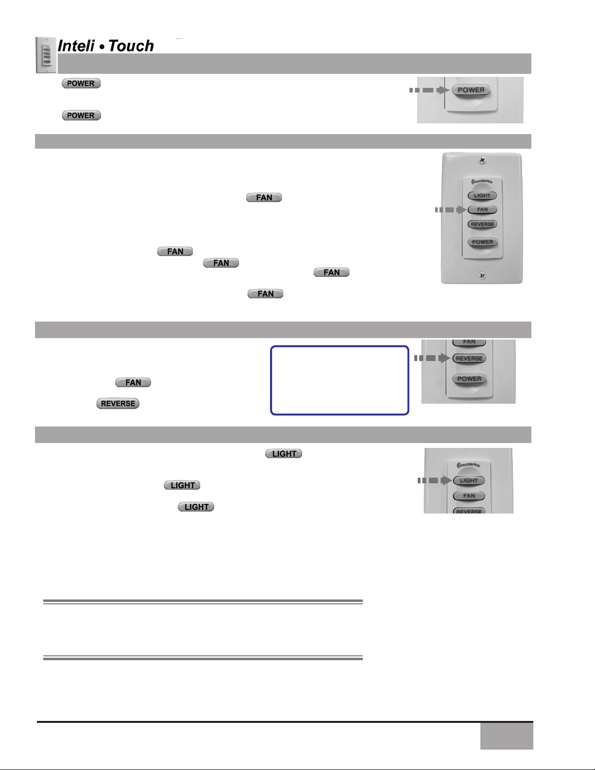
OPERATION © POWER
The button is normally left in the on position. Always turn the power off
during cleaning or servicing the fan and during thunderstorms. It is also used to
exit or enter additional programs.
The button must be left on to retain a previously set fan speed or light
level.
OPERATION SPEED CONTROL
There are six individual speed settings for the fan; each speed is indicated
by an audible tone of increasing pitch.
FAN CONTROL
To select the desired fan speed:
1. With fan off, press and hold the button labeled . The fan blades
will start rotating at the slowest speed, and will increase in steps.
2. Release the button when the desired speed is reached.
The fan speed is now in memory and will automatically come on at the
same speed each time the button is used. To maintain this level
of speed, turn the fan on by pressing less than one second. To
lower speed, turn fan off, then on by pressing and holding the
button until the desired speed is reached. When the fan is on, you may
increase the speed by pressing and holding the button until the
desired speed is reached, then release it.
ON - OFF:
A momentary
press of the FAN
button
CHANGE SPEED:
Press and hold
FAN button longer
than one second
OPERATION REVERSING AIRFLOW
The direction of airow can be changed from downward to upward or from upward to downward.
To reverse the airow:
1. Make sure the is on and blades are Turning.
2. Press the button.
Note: A four-toned signal
indicates the command was
accepted by the fan. A few
seconds later the fan will slow
to a stop and then reverse
direction.
OPERATION LIGHTS
To turn the lights off and on, press and release the button for less than
one second.
1) First press/release of the button- The light will turn ON.
2) Second press/release of the button- The light will turn OFF.
To vary the light brightness at each touch level:
To vary the light brightness:
1. With lights off, press and hold the button. After one second the lights will
come on at their lowest level and gradually become brighter.
NOTE: Light Operation - the light varies from “bright” to “dim” over
approximately 8 seconds. This sequence will reverse the light when it reaches
the brightest or dimmest level if you continue to hold the LIGHT button.
Release the button when the desired level is reached.
LIGHT CONTROL
ON - OFF:
A momentary press of
the LIGHT button
CHANGE BRIGHT-
NESS:
PRESS AND HOLD
LIGHT BUTTON
LONGER THAN ONE
SECOND
2. Release the button when the desired brightness level is reached.
The brightness level is now in the fan memory and will automatically come on at
the same brightness the next time the button is used.
5

®
3
CHANGING FREQUENCY SETTING
NOTE: All fans leave the factory set to
“1111”
You will only have to change the dip switch settings in the remote if you
are using more than one fan in the same area and want to control them
separately.
NOTE: DO NOT set dip switch setting in the remote
to ‘0000’, this may cause frequency interference from
other Casablanca Products.
Step 1. Turn power OFF at the circuit breaker or fuse box and at the toggle
switch, for the fan you want to change.
Step 2. Remove the screws and switch plate from the existing switch box.
Step 3. Remove the screws holding the switch in the switch box.
Step 4. Pull the existing W-85 switch from the switch box to expose the dip
switches located on the side of the control as shown in Figure #1.
Step 5. Change the dip switch settings, assuring that they are different from
the previously installed Inteli-Touch® 3 fan.
DIP
SWITCHES
DIP SWITCHES
SET TO ‘1111’
(Factory Setting)
DIP SWITCHES
SET TO ‘1001’
Step 6. Mount the W-85 Wall Control unit back into the wall electrical box.
Step 7. At the circuit breaker or fuse box and at the toggle switch, turn the
power off for the fan whose frequency you are changing.
Step 8. Within 20 seconds of restoring power to the ceiling fan and the
W-85 Wall Control press and hold both the “FAN” and “REVERSE” buttons
as shown in Figure #2 for 3 seconds, you will hear one tone from the Piezo
Buzzer indicating the command has been accepted.
AUTOMATIC DEMONSTRATION PROGRAM
Programmed into every Inteli-Touch® 3 Series fan
is an Automatic Demonstration Program. It can be
used to fully demonstrate and test the operation of
the fan.
To enter the demonstration program:
1. Turn off for at least 5 seconds. This will
clear the fan memory ready for programming.
2. Turn on.
3. Immediately operate the buttons in the following
sequence:
+
+
+ +
A multi-tone signal will verify the start of the test program which proceeds as follows:
• Lights slowly increase to full intensity.
• Fan accelerates to speed three with audio tones.
• Light dims to half intensity.
• Fan accelerates to full speed with audio tones.
• Fan reverses at full speed with audio tones.
• Fan operates at full speed.
• Fan turns off with audio tones (blades coast for a
short time).
• Lights turn off.
The complete cycle lasts slightly over one minute. It
will continue to repeat until the is turned off
for more than ve seconds, cancelling the program.
6

®
3
OPERATION SAFE-EXIT
NOTE: Both Light-Minder and Safe-Exit programs will always run at the same
time.
The Safe-Exit Program gives you about thirty seconds of light when you turn the
lights off, enabling you to exit your home before the lights go out. To enter the SafeExit Program:
1) To operate the lights for Safe-Exit Program – Press the button off for at
least ve seconds.
2) Turn the Power on. Immediately press the buttons in the following sequence:
+ + + . Immediately press the Button after an audio tone
is heard from the fan controller. The lights will blink to indicate this command has been
accepted. The lights will stay on for 30 seconds and then begin to dim. After thirty
seconds have elapsed, the lights will turn completely off.
3) To cancel the Safe-Exit Program, press the button off for ve seconds.
NOTE: If the lights are left on in the room, the lights will automatically turn
OFF after 2 hours. ( this is Light-Minder)
®
AND LIGHT-MINDER® PROGRAM
Safe-Exit
The Light-Minder Program automatically turns OFF the fan mounted lights after two
hours.
To enter the Light-Minder Program:
1) To operate the lights for Light Minder Program – Press the button off for at
least 5 seconds.
2) Turn the on. Immediately press the buttons in the following sequence:
+ + + . A series of tones will be heard through the piezo-
buzzer indicating the command has been accepted. Once the lights turn on, they will
automatically turn off after 2 hours.
3) Light operation still remains normal, if you leave the room and turn OFF the lights
will blink to indicate this Safe-Exit command has been accepted. The lights will stay
on for 30 seconds and then begin to dim. After thirty seconds have elapsed, the lights
will turn completely off.
4) To cancel the Light-Minder and Safe-Exit Programs, press the button.
OPERATION HOME-SAFE® PROGRAM
The Home-Safe Program makes an unoccupied home appear occupied by turning
the lights on and off at random times.
To enter the Home-Safe Program:
1) To operate the lights and fan for Home Safe Program – Press the But-
ton off for a least 5 seconds.
2) Turn the on. Immediately press the buttons in the following sequence:
+ + + . A series of tones will be heard through the
piezo-buzzer and ashing lights indicating the command has been accepted will
follow. This program overrides all manual control of lights and fan. Once the lights
turn on, they will automatically turn off after 2 hours.
3) The lights will automatically cycle on and off in a controlled sequence as follows:
ON 1 hour, OFF ½ hour, ON 2 hours, OFF 1 hour, ON ½ hour then OFF 2 hours.
This seven hour pattern will repeat continuously so that a different pattern of lighting
is seen each day of the week.
4) To cancel the Home-Safe Program, press the Button OFF for ve
seconds.
Light-Minder
7

®
3
OPERATION FAN-MINDER™ PROGRAM
The Fan-Minder feature will add to your comfort when used in the bedroom. The program
reduces the speed of the fan each two-hour interval to compensate for cooling night air.
To enter the Fan-Minder Program:
1. Turn the OFF for at least 5 seconds.
2. Turn the ON.
3. Immediately operate the buttons in the following sequence:
+
4. The fan will respond with three descending tones. A timer is now initiated and the fan will
reduce one speed for each two-hour interval. The fan will not, however, descend below
the second lowest speed.
5. You may increase the fan speed by pressing and holding the button until the
desired speed is reached, then release it. The fan will again reduce one speed for each
2 hour interval.
5. To cancel the Fan-Minder Program, turn the OFF for three seconds.
+
+
8

®
3
IN THE WALL BEZEL REPLACEMENT
WALL CONTROL AND HARDWARE (not to scale)
Switch Mounting
Screws (2)
W-85
Wall Control
WARNING!
To avoid possible electrical shock, make certain that electricity is turned off at the circuit
breaker or fuse box before attempting any installation or repair procedure
Switch Bezels
(1) White
(1) Almond
White Wall
Plate(1)
SCREWS
(2)
Almond Wall
Plate(1)
Wall Plate Screws
(2) White
(2) Almond
(4) Wire Cap
CAUTION! NOT turning the power OFF at the
circuit breaker or fuse box may cause damage to
the electronics within the wall control and or the PC
board on the fan.
W-85 Wall Control Bezel Replacement installation
as follows - (In the Wall Replacement):
Step 17a. Locate the two (2) screws holding the
switch plate too the wall control and remove the cover
plate as shown in Figure #1.
Step 17a. Locate the four (4) tabs holding the bezel to
the front of the switch, then press in on each tab one at
a time, removing the bezel as shown in Figure #2.
Step 17b. Locate the rubber key pad attached to
the four (4) locating pins as shown in Figure #2 and
remove rubber key pad from the WHITE bezel, also
as shown in Figure #2.
White Wall
Figure #1
BEZEL
BEZEL
TABS
Figure #1
9

®
3
W-85 Wall Control Bezel replacement: CONTINUED
Step 17c. Locate the rubber key pad attached to
the four (4) locating pins as shown in Figure #3 and
remove rubber key pad from the WHITE bezel, also
as shown in Figure #3.
LOCATING
PINS
HOLES(4)
WHITE
BEZEL
LOCATING
PINS (4)
RUBBER KEY
PAD
Figure #3
Step 17d. Reinstall the rubber key pad on to the
four (4) locating pins located on the almond bezel
as shown in Figure #4.
Step 16e. Before attaching the bezel back on to the
front of the switch, make sure that the rubber key
pad is attached to the locating pins on the bezel as
shown in Figure #5.
RUBBER KEY
PAD
ALMOND
BEZEL
ALMOND
BEZEL
RUBBER KEY
PAD
Figure #4
LOCATING
PINS
(4)
Figure #5
10

®
3
W-85 Wall Control Bezel replacement: CONTINUED
Step 16e. To attach the bezel back on to the front of the
switch you will need to align the four (4) tabs on the bezel
with the front of the wall control and by gently pressing on
both top and bottom of the bezel at the same time, snap
the bezel back on to the front of the switch as shown in
both gures #6 and #7.
BEZEL
BEZEL
TABS
BEZEL
ALIGNMENT
PIN AND HOLE
Figure #6
Step 16f. Re-attach the wall plate using the two (2)
almond colored head screw as shown in Figure #7, then
check your work by pressing on the light, fan, reverse
and power buttons, making sure that the buttons do not
stick and that each switch functions properly. Turn the
power back ON and test the fan and lights.
COLORED
ALMOND
WALL PLATE
SCREWS
ALMOND
BEZEL
ALMOND
COLORED
WALL PLATE
Figure #7
11

®
3
TROUBLESHOOTING TIPS
Please refer to this troubleshooting guide before requesting service or contacting your dealer for assistance.
PROBLEM POSSIBLE REMEDIES
Fan will not start • Check the main circuit fuses, circuit breakers, and wall switch position.
Check all wire connections. Make sure the power is turned off during this
inspection.
• Pin connectors are not making good contact. Check all connections.
• The fan receiver is defective. Replace the fan receiver.
• Reset the frequency setting: Turn the power off at the circuit breaker
for the fan that is not functioning only. Within 20 seconds from restoring
power to the ceiling fan and the W-85 Wall Control press and hold both
the “Fan” and “REVERSE” buttons as shown in Figure #2 for 3 seconds,
you will hear one tone from the Piezo Buzzer indicating the command
has been accepted. The Fan will come on at “low” speed in the reverse
direction.
Fan wobbles or shakes excessively • Be sure the canopy pin is set properly into the slot on the ball.
• Check that the blade holders have not been bent during installation and
the blades are balanced.
• The hanger bracket and/or the ceiling outlet are attached too loosely.
Make sure the hanger bracket is attached tightly to the ceiling outlet box
and the downrod assembly is secured rmly.
• The downrod is attached to the downrod base too loosely. Make sure all
the screws are securely tightened.
Fan is noisy during operation • When changing fan speeds, you may hear several audible clicks. This is
normal operation.
• Check and tighten the light xture retaining screws, glass shade screws,
and/or lightbulb(s).
• Tighten the canopy screws and mounting plate assembly. Make sure
the wire nuts inside the canopy and switch housing are not touching the
metal parts and that they have not fallen off the wire splices. Tighten as
necessary.
• Tighten the blade holders to the ywheel (or Direct Drive motor) and the
blades to the bladeholder screws.
• Make sure all the screws in the motor housing are snug but not overly
tight.
Fan does not run on low speed • If fan is new, it may need to be “broken in.” Run at high speed for several
days.
This device complies with RSS-210 of Industry Canada. Operation is subject to the following two conditions: (1) this device may not cause
interference, and (2) this device must accept any interference, including interference that may cause undesired operation of the device.
1. This device complies with part 15 of the FCC Rules. Operation is subject to the following two conditions: (1) this device may not cause
harmful interference, and (2) this device must accept any interference received, including interference that may cause undesired operation.
2. This equipment has been tested and found to comply with the limits for a Class B digital device, pursuant to Part 15 of the FCC Rules.
These limits are designed to provide reasonable protection against harmful interference in a residential installation. This equipment generates, uses and can radiate radio frequency energy and, if not installed and used in accordance with the instructions, may cause harmful
interference to radio communications. However there is no guarantee that interference will not occur in a particular installation. If this
equipment does cause harmful interference to radio or television reception, which can be determined by turning the equipment off and on,
the user is encouraged to try to correct the interference by one or more of the following measures: Reorient or relocate the receiving
antenna, Increase the separation between the equipment and receiver, Connect the equipment into an outlet on a circuit different from that
to which the receiver is connected. Consult the dealer or an experienced radio/TV technician for help. Note: Any changes or modications
to the transmitter or receiver not expressly approved by Casablanca Fan Company may void one’s authority to operate this remote control.
12

®
3
13

14
 Loading...