

INTRODUCTION
Before You Start 2
Safe Use 2
MOUNTING RECOMMENDATIONS
General Guidelines
.........................................................................................................................................................
3
Sloped Ceiling Installations
............................................................................................................................................
3
FAN INSTALLATION
Getting Started
...............................................................................................................................................................
4
Crossbar Mounting Bracket Installation
.........................................................................................................................
4
Lag Screw Installation
....................................................................................................................................................
5
Canopy Installation
.........................................................................................................................................................
5
Fan Preparation
...............................................................................................................................................................
6
Blade Installation
............................................................................................................................................................
7
Switch Housing Bracket / Cap Installation
....................................................................................................................
8
Hanging the Fan
.............................................................................................................................................................
9
Canopy Electrical Connections
.......................................................................................................................................
8
Canopy Hatch Installation
..............................................................................................................................................
8
VERSA
TOUCH2™ CONTROL
Control Bracket Installation
..........................................................................................................................................
Remote Operation
.........................................................................................................................................................
Changing Transmitter Frequency Setting
.....................................................................................................................
TROUBLESHOOTING TIPS
..........................................................................................................................................
......................................................................................................................................
AUTHORIZED SERVICE CENTERS
...........................................................................................................................
.......................................................................................................................................
ASSEMBLY DIAGRAM
...................................................................................................................................................
READ AND SAVE THESE INSTRUCTIONS!
CONTENTS
1
the circuit you will
the circuit you will
being installed, be careful not to mix blades from diff erent
very careful of the fan and blades. Always turn the power
All wiring must be in accordance with the National Electric Codes and the appropriate
is ceiling fan requires a grounded electrical supply of 120 VAC, 60 Hz and a minimum 15 amp circuit. e maximum
Where wire nuts are employed, be sure all bare wires are within the connectors. When installing the canopy hatch, make
INTRODUCTION
BEFORE YOU START
SAFE USE
2
Ceiling Height Pole Length
8
9
9
10
11
13
14
When to Use Extension Poles
Authorized Casablanca Dealer for details.
NOTE:
e fan may wobble or vibrate if the pole length
will solve the problem.
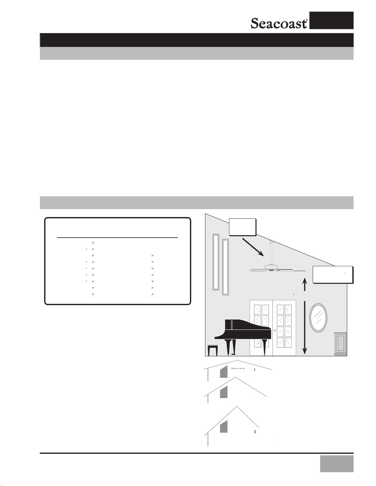
MOUNTING RECOMMENDATIONS
your fan.
GENERAL GUIDELINES
SLOPED CEILING INSTALLATIONS
3
After turning the power OFF at its source (either the circuit
breaker or fuse box), lower the old fi xture and disconnect the
wiring. Check the ceiling fi xture outlet box to be sure that
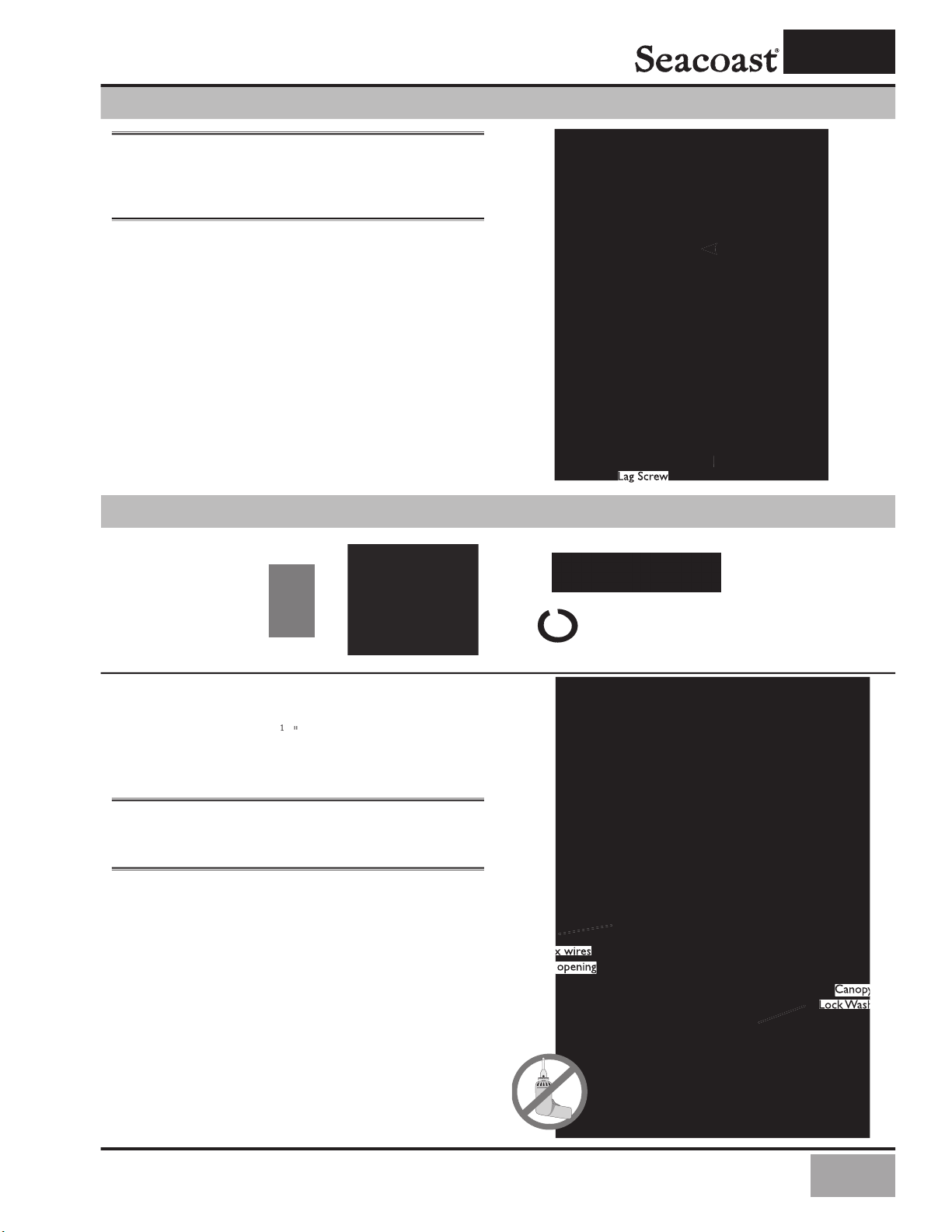
Wire Nut (4)
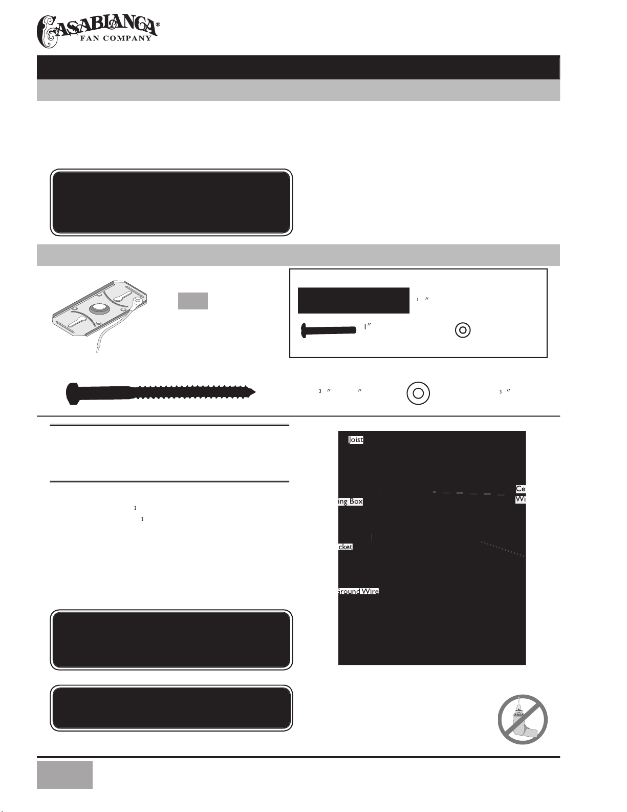
ADDITIONAL HARDWARE
x 8-32 Rounded Head Screw (2)
x 8-32 Rounded
#7 x 5
(1)
Joist
Wiring
Wiring Box
NOTE:
After removing the old fi xture, check the outlet box
Remove the knockout plug in the center of the
/
2
/
beam to a depth of 3 inches.
Route the outlet box wires through the center
washer.
FAN INSTALLATION
APPROVED OUTLET BOX
GETTING STARTED
WARNING: To reduce the risk of fire, electrical
shock, or personal injury, mount to outlet box marked
“Acceptable for Ceiling Fan Support” using the
mounting hardware provided with the outlet box.
CROSSBAR MOUNTING BRACKET INSTALLATION
CAUTION: To reduce the risk of personal injury,
use only the mounting hardware provided with the
approved outlet box to install the crossbar mounting
bracket.
WARNING!
Support directly to building structure only.
4
Attach the canopy to the crossbar mounting bracket
with three of the 8-32 x 2
/
2
long canopy screws and lock
washers provided with your Casablanca fan. Tighten using the
NOTE:
On sloped ceilings, align the canopy opening with
through canopy opening
NOTE:
We recommend that the ceiling box be of suffi cient
With the large washer attached, pass the lag screw
LAG SCREW INSTALLATION
CANOPY INSTALLATION
5

Using the provided Allen wrench, loosen the set
read the downrod into the motor coupling until it stops
Tighten the set screw securely with the provided
Allen wrench to ensure safe operation of your fan.
Slide the motor cover down so that it is fl ush against
Using the three provided screws, attach the motor
Place the motor cover on the downrod as shown.
Route the wires from the motor through the
Tip: e downrod has a tapered thread that is designed
Failure to fully lock in the downrod
before securely tightening the Allen set screw may
Allen Set Screw
FAN PREPARATION
Unsnap one of the switch housing brackets on
To reach the blade holder mounting holes in the
/
IMPORTANT SAFETY INFORMATION!
Before starting the installation of your ceiling fan, install the threaded
downrod into the motor coupling and lock the assembly
6

Washer
Remove the five shipping blocks attached to
Attach each blade to a blade holder by first
blade screws into the screwholes and tightening using the
BLADE INSTALLATION
Attach each blade/bladeholder assembly to the motor
by threading two blade holder screws through the matching
After all fi ve blade assemblies have been installed, tighten the
7

/
screws removed in Step 4h,
NOTE:
If you have purchased an accessory light fi xture for
SWITCH HOUSING BRACKET/ CAP INSTALLATION
Take the two switch housing bracket you removed
is is to prevent any wires getting pushed down near the
8

Tuck the wires into the canopy
with the wire nuts pointed upwards so
wires are clear of the canopy opening.
Install the canopy hatch with the
Straighten the fan, then check
between the canopy and the ceiling or
wiring by placing the bare ends of the wires side by side and
with wire nut.
NOTE:
Wire Nut
To hang the fan body in the canopy, hold the fan body
Trim excess motor wires, leaving at least 6 inches
/
2
HANGING THE FAN
CANOPY ELECTRICAL CONNECTIONS
CANOPY HATCH INSTALLATION
9

wall control/switch.
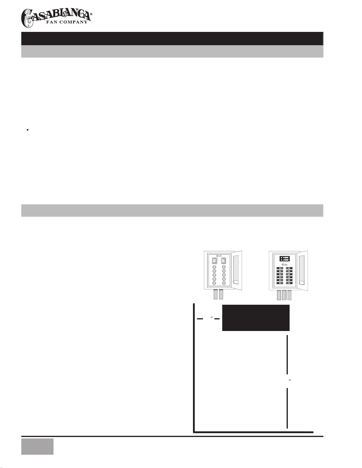
Wood
Anchor
W-73
Remove the two screws holding the switch cover plate.
Orient the control bracket as shown and line up the
Wall Installation
Locate a 2x4 wall stud
Orient the control
bracket as shown over the
2x4 stud.
Anchor
NOTE:
e wall anchors and 6-32 x 1" screws may
be used in situations where mounting to a stud is not
Wood
W-73
VERSA•TOUCH2™ INSTALLATION
VERSA•TOUCH2™ INSTALLATION HARDWARE
CONTROL BRACKET INSTALLATION
10

To start the fan. Press the selected speed button to run the fan at the desired speed.
To turn off the fan. Press the FAN OFF button.
Airfl ow Direction
To reverse the airfl ow press the REVERSE button. Reverse operates at any speed whether
Turn the light on or off independently from the fan by pressing the UP LIGHT DOWN
Auto Resume
2. Turn the power off to the fan (from the circuit breaker) for at
You will only have to change the dip switch settings in the remote if you are using more
At the circuit breaker or fuse box, turn the power off for the fan you want to
Open the battery door of the Versa•Touch control and remove the battery.
Change the dip switch settings, assuring that they are diff erent from the previously
At the circuit breaker or fuse box, turn the power back on for the fan whose
Within 20 seconds of restoring power, push the Hi, Med, and Lo buttons (in
Note: All fans leave the factory set to ‘00000’.
Within 20 seconds of turning
the fan on, press in this order to
3 - HIGH
1 - LOW
HIGH MED LOW
WARNING: Do not turn the power off at the circuit breaker, then
back on, for the previously installed Versa•Touch 2 fan(s), as you
REMOTE OPERATION
versa•touch 2 control
TRANSMITTER FREQUENCY SETTING
IF FAN DOES NOT WORK
11

TROUBLESHOOTING TIPS
• Check the main circuit fuses, circuit breakers, and wall switch position. Check all
wire connections. Make sure the power is turned off during this inspection.
• e 9-pin connector is not making good contact. Check the 9-pin connector in
• e battery is weak. Install a fresh battery.
• e fan receiver is defective. Replace fan receiver.
• Check the frequency setting: Turn the power off at the circuit breaker, only for
• Be sure the canopy pin is set properly into the slot on the ball.
• Check that the bladeholders have not been bent during installation and the blades
• e hanger bracket and/or ceiling outlet are attached too loosely. Make sure
• e downrod is attached to downrod base too loosely. Make sure all the screws are
• Check and tighten the light fi xture retaining screws, glass shade screws, and/or
• Tighten the canopy screws and mounting plate assembly. Make sure the wire nuts
• Tighten the blade holders to the fl ywheel (or direct drive motor) and the blades to
• Make sure all screws in the motor housing are snug but not overly tight.
• If fan is new, it may need to be “broken in.” Run at high speed for several days.
• Replace with alkaline batteries.
• e 9-pin connector is not making good contact. Check the 9-pin connector
• e fan receiver is defective. Replace fan receiver.
• e fan receiver is defective. Replace fan receiver.
• e fan receiver is defective. Replace fan receiver.
• e fan receiver is defective. Replace fan receiver.
• ere is frequency interference. Change frequency as described on Page 11.
• Check that antenna wire is not touching metal plate.
• e fan receiver is defective. Replace fan receiver.
• e fan receiver is defective. Replace fan receiver.
• e light socket is broken. Replace socket.
• A lightbulb is defective. Replace lightbulb.
12

is device complies with Part 15 of the FCC rules. Operation is subject to the following two conditions:
2. This device must accept any interference received, including interference that may cause undesired operation.
is equipment has been tested and found to comply with the limits for a class B digital device, pursuant to Part 15 of the
is equipment generates, uses, and can radiate radio frequency energy and, if not installed and used in accordance with the
will not occur in a particular installation. If this equipment does cause harmful interference to radio or television reception,
which can be determined by turning the equipment off and on, the user is encouraged to try to correct the interference by
NOTE: Any changes or modifi cations to the transmitter or receiver not expressly approved by Casablanca Fan Company
CARE RECOMMENDATIONS
as these will damage the fi nish.
be applied for added protection and beauty.
No Need for Lubrication
Never lubricate this fan!
e precision motor at the heart of your Casablanca fan features sealed bearings that are lubricated
For questions or to locate the nearest Casablanca Authorized Service Center,
call 1-888-335-5247 toll-free, or visit us on the Web at www.casablancafanco.com.
13

AUTHORIZED SERVICE CENTERS
ALASKA
ANCHORAGE 99518 PRIMARY ELECTRIC INC. 907-563-7988
ARIZONA
YUMA 85364 CURLEY’S LITEHOUSE 520-782-4353
YOUNGTOWN 85363 QUALITY HOME FAN DOCTOR 602-274-6649
ARKANSAS
AUBURN 95603 THE FAN DOCTOR 530-823-8768
CLARITA
ATASCADERO 93422 MC NAMARA ELECTRIC INC. 805-466-1854 ISO/OWTS,
VALENCIA 91354 FANTASTIC FAN SERVICE 800-800-3871
AIEA 96701 THE FAN SHOP, INC. 808-488-1221 OWTS
YORKVILLE 60560 UNIFIED SUPPLY INC. 630-553-0660
VALPARAISO 46383 D & K ELECTRIC 219-464-7576
= IN-SHOP ONLY
= PRODUCT SOLD BY DEALER
= BOTH
14

ALBUQUERQUE 87123 FRANK’S ELECTRIC 505-293-6724 ISO
ALBUQUERQUE 87112 A-1 LAMP DOCTOR 505-296-5050
ALBUQUERQUE 87109 B-ELECTRIC 505-828-0241 SANTA FE
ALBANY 12205 BERT ELECTRIC 518-869-7140
YONKERS 10704 JAY D. KOSACK 914-237-9051
AMHERST 14228 SHANOR LTG. CTR. 716-691-3622 ISO
AMHERST 14226 ROYALITE INC. 716-832-1492 ISO
15

ALLENTOWN 18105 LIGHTING FIXTURE & SUPPLY CO 610-435-9691
ALLENTOWN 18102 SCHOLL’S ELECTRIC 610-435-5876
AMARILLO 79106 DI’S LAMP & FAN REPAIR 806-331-5267
AUSTIN 78757 KLOCK ELECTRIC 512-837-4704
ARLINGTON 76001 P&M QUALITY CONT. 817-478-2004
AUSTIN 78703 TEXAS CEILING FANS/CEILING FAN SHOP 512-477-3132 ISO
VICTORIA 77904 HALL ELECTRIC CO., INC. 512-578-6221
VIRGINIA
VIRGINIA BEACH 23451 FANS,LIGHTING, ‘N’ MORE 757-422-3616
WASHINGTON
YACOLT 98675 S&L ELECTIRC 503-657-0633
YAKIMA 98902 INLAND LIGHTING 509-248-4647 ISO
WASHINGTON, DC
WEST VIRGINIA
WISCONSIN
PRODUCT SPECIFICATIONS
Casablanca Signature
Seacoast
C3U72M
A = 16
B = 17
B = 17
C = 3
D = 11.8"
E = 5.6
E = 5.6
Weight:
50 lbs.
Archetectural White
188 x 20 mm - C1LT type
54 inches
15 degrees
No. of blades:
5
Technology:
Versa•Touch2™
45-watt tube light with 44,000-hour
bulb life
No. of lightbulbs:
3
NOTE:
Dimension
16
 Loading...