


CANDELIER™ OWNER’S MANUAL
READ AND SAVE THESE INSTRUCTIONS!
Safety and the proper operation of your Casablanca fan require both a thorough knowledge of the product and proper installation.
Therefore, before attempting to install and operate your Casablanca fan, read this Owner’s Manual completely and carefully.
Retain this manual for future reference.
CA UTION : To avoid possible electrical shock, make certain that electricity is turned off at the circuit breaker or fuse box before
attempting any installation procedure.
CONTENTS
INTRODUCTION .....................................................................................................................................................................2
Before You Start ....................................................................................................................................................................2
Safe Use ................................................................................................................................................................................. 2
MOUNTING RECOMMENDATIONS ...................................................................................................................................3
General Guidelines ................................................................................................................................................................ 3
Sloped Ceiling Installations ..................................................................................................................................................3
FAN INSTALLATION .............................................................................................................................................................4
Getting Started ......................................................................................................................................................................4
Crossbar Hanging Bracket Installation .................................................................................................................................4
Canopy Bracket Installation ..................................................................................................................................................5
Installing Canopy Cover........................................................................................................................................................5
Installing Downrod ...............................................................................................................................................................6
Hanging The Fan ................................................................................................................................................................... 6
Canopy Electrical Connections ............................................................................................................................................. 7
Fan Blade Installation ............................................................................................................................................................7
Halogen Bulb Installation ......................................................................................................................................................8
Removing Flicker Bulbs From Packaging ............................................................................................................................8
Candle Installation ................................................................................................................................................................ 9
™
INTELI•TOUCH
CARE RECOMMENDATIONS ............................................................................................................................................12
TROUBLESHOOTING TIPS ................................................................................................................................................. 13
PRODUCT SPECIFICATIONS .............................................................................................................................................. 14
AUTHORIZED SERVICE CENTERS .................................................................................................................................. 15
CONTROL INSTALLATION ................................................................................................................. 10
1

INTRODUCTION
BEFORE YOU START
• CAUTION: RISK OF ELECTRICAL SHOCK! Installation is to be in accordance with the National Electrical ANSI/NFPA 701999 and local codes. If you are unfamiliar with the wiring codes, you should use a qualifi ed electrician. To av oid ov erheating
and possible damage to other equipment, do not install control to a receptacle, fl uorescent light fi xture, operating appliance,
or transformer-supplied appliance.
• This fan should be installed over an UL Listed electrical outlet box, and be mounted directly to a structural support. If the
electrical outlet box does not meet these guidelines, a new box must be installed.
• Casablanca extension poles may be available for this model. Accessory downrods are available in lengths from 12 inches to
117 inches. Ask your authorized Casablanca dealer for details.
• This ceiling fan requires a grounded electrical supply of 120 VAC, 60 Hz and a minimum of 15-amp circuit. The maximum
current required for the fan with light fi xture is 2.77 amps. The fan uses about 0.9 amps (108 watts ) . Maximum light current
is about 1.87 amps (224 watts) of lighting.
• Where wire nuts are employed, be sur e a ll bare wi r es are within the connectors. When installing the canopy, make sure all
wires are within the canopy and that no wires are being pinched.
• WARNING: Do not insert foreign objects in between the rotating fan blades.
• WARNING: T o reduce the risks of fi re or electric shock, do not use this fan with any solid-state control device. Use only the
control provided with or recommended for this fan.
• WA RN ING: Do not remove stickers f rom the Ca ndelier fi xtur e. Each numbe red sticker cor respond s to a candle siz e and
shape, and will be necessary to properly install the candles.
Unpacking
Prior to assembling and installing your ceiling fan, remove all parts from the shipping cartons and check them against the parts
listed in the Parts Guide. Do not remove lightbulbs from their packagi ng until you are rea d y t o instal l them. Before discarding
packaging materials, be certain that all parts have been removed. If loose Styrofoam is stuck to the Candelier fi xture, use a clean,
dry paintbrush to remove small Styrofoam pieces. Do not brush Styrofoam into wiring cavities.
For best performance and for your warranty to be valid,
use only genuine Casablanca blades and accessories.
SAFE USE
• The blades in each pack are matched for equal weight to
assure smooth fan operation. If more than one fan is being
installed, do not mix blades from different cartons.
• Inspect the contents of your carton for possible shipping
or handli ng damage. If par ts are m issing or dama ged,
call 1-888-227-2178.
• You will need a t ota l of th ree pe ople to inst al l th is fa n.
(Approximate weight is 150 lbs.)
• When clean ing, pai nting, or work ing nea r your fan , be
cautious of the fan and blades. Always turn power to the
ceiling fan OFF b efore replacing l ightbu lbs or working
on your fan.
• Never insert anything into the path of the fan blades while
the fan is in operation.
• Never install a fan over a pool or spa.
• Never operate a fan that has b ee n damaged i n a ny way.
For assistance in obt aining service, cont a ct Ca s ablanca
Fan Company toll-free at 1-888-22 7-2 1 7 8, or contact your
local Authorized Casablanca Dealer.
Fuse Box
(Remove fuse for the
circuit you will be
working on)
24" ↑
Dimensions indicated are the minimum
allowable for proper installation.
Circuit Breaker
(Trip breaker for the
circuit you will be
working on)
48"↑
84" ↑
12 1/2" ↑
from bottom
edge of blade
to fl oor
2
CANDELIER
MOUNTING RECOMMENDATIONS
GENERAL GUIDELINES
Before mounting your Casablanca Candelier, read the following helpful recommendations.
The location of the fan, ai r circu lation, and fa n size are all i mpor tant fact ors to consider
before installation.
Location
Ceiling fan s have practical uses in almost ever y room in your home, but the Candelier
fi xture is intended for use in larger rooms. Keeping that principle in mind, we suggest you
follow these mounting rec ommendat ions as you decide where to i nstall you r Casablanca
Candelier.
• For safety reasons, the fan blades must be a minimum of 7 feet above the fl oor.
• Do not install the fan in a doorway or above a swinging door.
• In bedrooms, fans work best when mounted above the foot of the bed.
• Over pool tables, be sure to provide plenty of clearance to avoid damage from
pool cues.
• Do not instal l a fan close to or over a pool or spa. High hum idity combi ned
with corrosive gases will destroy the fi nish and warp the fan blades.
™
LAG SCREWS
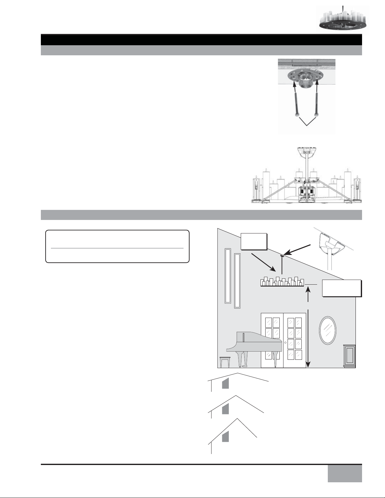
SLOPED CEILING INSTALLATIONS
STANDARD CEILING REQUIREMENTS
Ceiling Height Pole Length
9' 0" Standard
9' 6" Standard
The Candelier is not designed to be mounted on a ceiling
sloped greater t han 30 degrees. Mount the Candelier
Crossbar Hanging Bracket with the opening pointed either
up or to the side, depending on installation. The Candelier
canopy cover has been eng ineer ed to mount fl ush to the
ceilin g, wi th th e can opy insert swi v elin g to ac commo date
mildly sloped ceilings.
EXAMPLE 1
EXAMPLE 2
Down
Rod
Maximum
angle 30º
Blades must be a
minimum of 7 feet
above the fl oor
7' minimum
This slope is less than 30º.
It is OK to install your fan.
This slope is 30º. This is the
maximum slope that will allow the
fan to hang straight down. It is OK
to install your fan.
EXAMPLE 3
This slope is more than 30º. Your
fan will not hang straight down.
Specialized installation is required.
3

FAN INSTALLATION
GETTING STARTED
Installing a New Ceiling Fixture Outlet Box
If you do not have an existing fi xture located whe re you
wish to place your Casablanca Candelier, an approved
ceiling fi xture outlet box must be installed and wired.
WAR NING:
The Candelier must be mounted directly to a
structural member of the ceiling. It cannot be
mounted directly to the outlet box.
CROSSBAR HANGING BRACKET INSTALLATION
PARTS NEEDED FOR THIS SECTION:
CEILING HARDWARE (not to scale)
Crossbar Hanging Bracket
Using Existing Ceiling Fixture Outlet Box
After turning the power OFF at its source (either the circuit
breaker or fuse box), l ower the old fi xture and disconnect the
wir ing. T he Candelie r is not to be sup por t ed by the cei li ng
box. It must be direct ly mounted to the suppor t struct ure
over an approved electrical outlet box. Please consult a
licensed elect rician to confi r m the right suppor t struct ure
is being used.
NOTE: The weight of this fan is approximately 150 pounds.
Lag Screw
NOTE: If you have removed an old fan fi xture, check the outlet
box to ensure that a joist or beam supports it across the upper
surface. If not, a 2 x 4 stud must be installed.
Step 1a. Hold the crossbar hanging bracket up to the ceiling.
Use a pen or pencil to mark screw placement through the two
holes in the bracket. With a 9/32 inch drill bit, drill two holes
angled outwa rd (away from the fi xture) at approximately a
four-degree angle.
Step 1b. Insert lag screws into the hanging bracket holes at a
four-degree angle. Tighten bolts until they are secure against
the ceiling.
CAUTION:
T o reduce the risk of personal injury, use only the
mounting hardware provided with the approved
outlet box to install the crossbar mounting
bracket.
LAG SCREW
4

CANOPY BRACKET INSTALLATION
PARTS NEEDED FOR THIS SECTION:
CANOPY BRACKET HARDWARE (not to scale)
CANDELIER
™
Canopy Bracket
Grommets
Wood
Screws
Step 2a. Hold the canopy bracket up to the ceil ing with the ‘lip’ side
facing the fl oor. Use a pen or pencil to mark screw placement through
the holes in the bracket.
Step 2b. Insert three black rubber grommets to the canopy bracket as
shown. The bracket is then installed facing the ceiling.
Step 2c. Drill holes on both sides of canopy bracket for even support.
Select the set of screws most appropriate for your installation.
Step2d. Use one of the following screw combinations:
A. Wood screws and washers
B. Long wood screws and washers
C. Sheetrock anchors
Option 1: Using Wood Screws
Instal l screws a nd washer s th rough t he holes in the ca nopy bracket.
Tighten screws until they are secure against the ceiling.
Option 2: Using Sheetrock Anchors
Instal l sheetrock anchors th rough the holes in the canopy bracket.
Tighten anchors until they are secure against the ceiling.
Long Wood
Screws
Sheetrock
Anchor Washers
INSTALLING CANOPY COVER
PARTS NEEDED FOR THIS SECTION:
CANOPY COVER HARDWARE (not to scale)
Downrod
#8-32 x 1/4"
Screws
Step 3a. Slide the hangi ng bracket support ri ng on to
the downrod . Then, slide the downrod cover over the
downrod. The base of the downrod should sit securely on
the rubber gasket inside the downrod cover.
Step 3b. Place the downrod (with the down rod cover
attached) inside the canopy cover. The edge of the
downrod cover should sit secu rely on the rubbe r gasket
inside the canopy cover.
Support
Ring
Downrod
Cover
Canopy
Cover
5
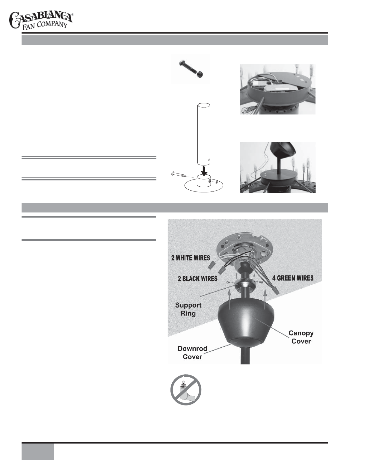
INSTALLING DOWNROD
Step 4a. Unscrew and remove both pieces of the control
housing cover. Set the control housing cover and six
screws aside. You will re-inst all the control housing
cover in Step 4e.
Step 4b. Unscrew and remove cross bolt and nut fr om
downrod adapter tube in center of control housing.
Step 4c. Thread black, white, and green wires up through
downrod, tightening to the base of the downrod adapter
tube in the control housing structure.
Step 4d. Slide downrod i nto downrod adapter tube
making sure no wires are pinched. Place your thumb on
the end of the cross-bolt. Insert the cross-bolt until its fl at
end is fl ush with the downrod adaptor tube. Re-attach the
nut, and tighten fi rmly with 7/16" wrench.
NOTE: Be careful not to cut or pi nch the wires when
inserting the cross-bolt.
Step 4e. Use the parts you set aside in Step 4a to replace
the control housing cover and screw it back into place.
HANGING THE FAN
Cross Bolt
and Nut
NOTE: You wi ll need at least two assistants for th is
step.
Step 5a. Have your assistant(s) help you lift the Candelier
fi xture to the ceiling.
Step 5b. Inser t the downrod ball into op ening in the
crossbar hanging bracket.
Step 5c. Slide the hang ing bracket supp ort r ing up the
hanging bracket, and screw it into plac e u sing the th re e
#8-32 x 1/4" screws.
6

CANOPY ELECTRICAL CONNECTIONS
Step 6a. Atta ch the fan w ires (coming f rom the down rod)
to the ceili ng fi xt ure outlet box wi ri ng by placing the ba re
ends of the wires side by side and then securing with a wire
nut. Test that the connection is secure by pulling on the wire
nut. Connect in this order:
• GREEN wire lea ds fr om mounti ng plate and down rod
assembl y of fan to GROUND conductor of power source.
Secure with a wire nut.
• WHITE wire from fan connects to white NEUTRAL
wire in ceiling fi xture outlet box. Secure with wire nut.
• BLACK power wire from fan connects to BLACK power
wire in ceiling outlet box. Secure with wire nut.
Afte r making the wi re connections, t he wires should be
spread apart with the grounded conductor and the equipmentground ing conductor on one side of the outlet box and t he
ungrounded conductor on the other side of the outlet box.
NOTE: If your ceiling wires are different from those
described above, consult an electrician.
CANDELIER
™
Step 6b. After connecting wiring, slide the canopy cover up
and into place. Make sure the canopy cover tabs are properly
aligned with t he canopy bracket and securely locked into
place.
FAN BLADE INSTALLATION
PARTS NEEDED FOR THIS SECTION:
FAN BLADE HARDWARE (not to scale)
Fan Blades
Blade Screws
Step 7a. Unscrew the bottom cover fi tter plate and
set the cover and screws aside. You will reinst all
them in Step 7c.
Step 7b. Make sure that the label “THIS SIDE UP”
is not visible when the blades are instal led . Please
note the label is installed on the actual fa n blade s.
Insert the fi rst fan blade into one of the slante d
opening b eneath the control housing. Secu re the
blade with black blade screws and washers (3 screws
and washers p er blade). Repeat th is process unti l
all three blades are installed.
Step 7c. Re-attach t he bottom cover fi tter plate,
using the screws you set aside in Ste p 7a. Secure
the motor end cap by twisting it into place.
Washers Motor End Cap
7

HALOGEN BULB INSTALLATION
Step 8a. To install or replace the h alogen bulbs, fi rst
remove the bulb covers.
• Loosen the round knurled nuts.
• Slide out the plastic halogen bulb covers (both covers
are the same part; they fi t together).
Step 8b. Carefully remove halogen bulbs from packaging.
There are 8 halogen bulbs provided.
Step 8c. Locate t he halogen sockets inside the w iring
cavities. Plug each halogen bulb into a socket, as shown.
Step 8d. Hold the halogen bulb caref ully by the socket.
Press the bulb into the bulb casing with gentle pressure.
Step 8e. Reverse instructions in Step 8a to re-install the
halogen bulb covers.
Halogen Bulb
REMOVING FLICKER BULBS FROM PACKAGING
NOTE: The Candelier fl icker bulbs are extremely fragile,
and should be handled with care.
Step 9a. Remove any remaining packaging material from the
Candelier fi xture. Carefully unwrap the plastic packaging from
the cardboard case of bulbs. Keep the case on a hard surface,
for stability.
Step 9b. Remove each bulb carefully, handling it by the white
plastic base, as shown. T here are 53 bulbs provided. (Five
bulbs are “extra”.)
Step 9c. With the Candelie r h anging f r om t he c ei l ing, inst a l l
the fl icker bulbs. Beginn ing w ith the i n ner row in the ci rcle,
and moving out in a circular pattern, screw individual fl icker
bulbs into each so cket car ef u l ly. Do not bump bulbs togethe r
or brush agai nst them, as it may dama ge the fragile natu re
of the wir ing system. Use extreme caution when ha ndling
fl icker bulbs.
Flicker Bulbs
Flicker Bulb
(installed)
8

CANDLE INSTALLATION
W ARNING: Use caution when installing candles.
Flicker bulbs are extremely fragile.
Step 10a. Careful ly remove candles from packagi ng materials.
There will be 48 candles, of varying colors and sizes.
Step 10b. Note the number on the bottom of each candle. This
number will correspond to a numbered socket where the candle
belongs on the Candelier fixture. Candles and sockets are
numbered for t he width and height of each candle. The colors
will vary. Carefully lower each candle over the bulb, letting it rest
securely on the metal surface. Repeat this process until all candles
have been placed on the Candelier fi xture.
NOTE: The fi ve spare fl icker bulbs are containe d i n a smal l box
labeled “Extra Bulbs.” Casablanca will replace up to fi ve addition a l
fl icker bulbs, if nece ssary. Do not throw away the Extr a Bulbs
box. T o request replacement fl icker bulbs, fi ll out the Flicker Bulb
Replacement Request card , place fi ve burned- out bulbs and the
card in the Extra Bulbs box, and seal the box. Apply the “Business
Reply Label” to the top of the box and put it in t he mail. ( Both
the Flicker Bulb Replaceme nt Request ca rd and Bu sines s Reply
Label can be found in your Owner’s Manual packet.) Casablanca
will ship the replacement bulbs to you at no charge.
CANDELIER
™
FLICKER BULB REPLACEMENT REQUEST CARD
When you have used the fi ve extra fl icker bulbs included with your Candelier fan, Casablanca will provide fi ve
additional spares at no charge. Simply complete this card, place it in the Extra Bulbs box with fi ve burned-out fl icker
bulbs, seal the box, apply the pre-paid Business Reply Label to the top, and mail the package.
Candelier Model Number
(can be found on fan or inside front cover of Owner’s Manual)
Customer Name
Shipping Address (not a PO Box)
City State Zip Code
Phone number E-mail address
C16G73T
Serial Number
SAMPLE
Offer limited to fi ve additional spare fl icker bulbs per Candelier fan.
SAMPLE
9

INTELI•TOUCH™ CONTROL INSTALLATION
INSTALLING THE W-32 WALL CONTROL
The wall control installs in the same manner as an ordinary light switch, using an existing wall box and wiring. This controller
is designed to signal t he fan microcomputer a s well as perform nor mal switching ope rations. For this reason the following
precautions must be observed:
1. Use only the Casablanca W-32 wall control.
2. Do not use any additional control with your Inteli-Touch fan
(for example, dimmer, fan speed control, etc.).
INTELI•TOUCH™ SINGLE W-32 INSTALLATION
CAUTION!
Ensure power is turned OFF at the breaker or fuse panel before starting installation.
W-32 is used to describe either white (-11) or ivory fi nish.
1. Remove the screws and switch plate from the existing switch box.
2. Remove the screws holding the switch in the switch box.
3. P ull the existi ng switch from the switch box to expose the w ire
connections.
4. Remove the two wires from the switch.
5. Connect the two wires just removed from the switch to the W-3 2 wall control
black wire and black/white stripe wire. Secure these connections with wire
nuts.
6. Connect the gree n ground wire coming fr o m the back of the W-32 control
to the ground wire in the switch box. Secure the splice with wire nut.
7. Install the W-32 in the wall box with the two long screws provided.
8. Install the wall plate with the two color matched screws.
NOTE: If wall control operation is reversed (fan switch controls lights and
light switch contr ols f an) turnoff the powe r a t t h e b r e aker or f use panel, then
swap the two W-32 black/white stripe wires.
3. Do not use more than one fan per wall control.
4. No other light fi xtu res or electrical appliances may be
connected on the circuit controlled by the W-32 wall
control.
INTELI•TOUCH™ DUAL W-32 INSTALLATION
CAUTION!
Ensure power is turned OFF at the breaker or fuse panel before starting installation.
To control the fan a nd light s fr om two loc ation s (a three -way cir cuit), use 2
W-32 wall controls.
1. Remove th e sc r ews and switch pl at e from the ex i sting sw it ch box a nd t h e
screws holding the switch in the switch box.
2. P ull the existi ng switch from the switch box to expose the w ire
connections.
3 Determ ine which wi r e i s c onnect e d t o the comm on t erm i nal of the 3-way
switch. (The terminal will be marked on switch).
4. Remove the wire from the common terminal of the 3-way switch. Connect
this w ire to t he rem ain ing bla ck/wh ite st rip ed wi re on the W-32 control.
Secure this splice with a wire nut.
5. Remove the t wo rem ai n ing w i res f ro m the 3 -way sw itch. C on nec t one of
these w ire s to a bla ck wi re on t he W-32 control. Secu re th e splice w ith a
wire nut. The remaining wire is to be connected to the other black wire on
the W-32.Secure the splice with a wire nut.
6. Connect the gree n ground wire coming fr o m the back of the W-32 control
to the ground wire in the switch box. Secure the splice with a wire nut.
7. Install the W-32 in the wall box with the two long screws provided.
8. Install the wall plate with the two short color-matched screws provided.
9. Installation of the second W-3 2 control is identical. Repeat steps 1 through 7.
NOTE: If wall control operation is reversed (fan switch controls lights and
light switch controls fan) turn off the power at the breaker or fuse panel, then
swap the two W-32 black/white stripe wires.
10

POWER
The POWER button is normally left in the on position. Always turn the power
off dur i ng clea ni ng or se r v icin g the f an a nd du r i ng thu nd er storms. It is a lso
used to exit or enter additional programs.
POWER must be left on to retain a previously set fan speed.
SPEED CONTROL
CANDELIER
™
There are four individual speed settings for the fan; each speed is indicated by
an audible tone of increasing pitch.
To select the desired fan speed:
1. With fan of f, pr ess a nd hold the b utt on lab eled FAN. The fa n blad es w ill
start rotating at the slowest speed, and will increase in steps
2. Release the button when the desired speed is reached.
The fan s peed is now i n m emory and will a utomatic a lly come on at t h e s ame
speed each time the FAN button is used. To maintain this level of speed, turn the
fan on by pressing FAN less than one second. To lower speed, turn fan off, the
non by pressing and holding the FAN button until the desired speed is reached.
When t he fa n is o n, you m ay in cr ea se t he sp ee d by pr es sin g an d holdi ng t he
FAN button until the desired speed is reached, then release it.
REVERSING AIRFLOW
The di rection of airf low can be changed f rom
downward to upward or from upward to downward.
To reverse the airfl ow:
1. Make sure the FAN is on.
2. Press the REVERSE button.
NOTE: A four-toned signal indicates the com mand
was accepted by the fan. A few seconds later the fan
will slow to a stop and then reverse direction.
LIGHT
To turn th e lights off a nd on, pres s and releas e the LIGHT bu tton for less
than one second.
FAN CONTROL
ON - OFF
A momentary press
of the FAN button
TO CHANGE SPEED
Press and hold FAN
button longer than
one second
LIGHT CONTROL
ON - OFF
A momentary press of
the LIGHT button
R
R
R
11

CARE RECOMMENDATIONS
Fan Finishes
• For cleaning, a soft brush or lint-free cloth should be used to prevent scratching the fi nish.
• Surfa ce smudges or a n ac cu mulat ion of dirt and dust ca n be re moved easily using a m ild dete rgent a nd slightly da mpene d
soft cloth. An antistatic agent may be used (on the fan base and blades only), but nev er use abrasive cleaning agents as these
will damage the fi nish.
Candles
NOTE: Remove candles from the Candelier fi xture to clean them. Replace candles carefully!
• Clean the Candelier candles with lukewarm water and mild soap. Do not use abrasive cleaning agents.
Blades
• Wood-fi nish blades should be cleaned with a furniture polishing cloth. Occasionally, a light coat of furniture polish may be
applied for added protection and beauty.
• For painted and high-gloss blades, surface smudges or an accumulation of dirt and dust can be removed easily using a mild
detergent and slightly dampened soft cloth. An antistatic agent may be used, but never use abrasive cleaning agents as these
will damage the fi nish.
No Need for Lubrication
• Never lubricate this fan! The precision motor at the heart of your Casablanca fan features sealed bearings that are lubricated
for life.
• Do not attempt to oil the motor.
Changing Lightbulbs
• Be sure to turn the power to OFF at the wall switch or circuit breaker before changing lightbulbs.
• Replace bulbs with the same type as you removed from the light fi xture.
• Use only the approved fl icker lightbulbs for the candles in your Candelier fi xture. C o n t ac t your C as a blan c a r e pr e s entative t o
order replacement bulbs.
• Use only the recommended halogen lightbulbs for the downlights in your Candelier fi xt u re.
12

CANDELIER
™
TROUBLESHOOTING TIPS
Please refer to this troubleshooting guide before requesting service or contacting your dealer for assistance.
PROBLEM POSSIBLE REMEDIES
Fan will not start • Check the ma in ci rcuit f uses , circu it breaker s, and wa ll switch p osition. Check
all wire connections. Make sure the power is turned off during this inspection.
• The fan receiver is defective. Replace the fan receiver.
• Check the frequency setting: Turn the power off at the circuit breaker for the fan
that is not fu nctioni ng only. Check that the jumpe r switches mat ch in both the
receiver and the transmitter.
Fan wobbles or shakes excessively • Be sure the canopy pin is set properly into the slot on the ball.
• The hanger bracket is attached too loosely . Make sure the hanger bracket is attached
tightly to the ceiling and the downrod assembly is secured fi rmly.
• The downrod is attached to the downrod base too loosely . Make sure all the screws
are securely tightened.
Fan is noisy during operation • Tighten the canopy screws and mounting plate assembly. Make sure the wire nuts
inside the canopy and sw itch housi ng are not touch ing t he metal pa r ts a nd that
they have not fallen off the wire splices. Tighten as necessary.
• Tighten the blade holders to the fl y wheel (or direct d r ive motor) and the blades
to the bladeholder screws.
• Make sure all the screws in the motor housing are snug but not overly tight.
Fan does not run on low speed • If fan is new, it may need to be “broken in.” Run at high speed for several days.
13

PRODUCT SPECIFICATIONS
Model name: Candelier
Model number: C16GxxT
Dimensions:
A = 15.44"
B = 10.93"
C = 13.44" as sold "/ 117.91" with accessory downrod
D = 2.07"
E = 4.82"
F = 8.00"
Light fi xture diameter = 48"
Weight: approximately 150 lbs.
™
Motor: XLP-Plus®
Blade span: 30"
Blade iron pitch: 20°
No. of blades: 3
Technology: Inteli•Touch
Ceiling height: 9' minimum
Lighting
Uplights: 48, 3-watt fl ickering bulbs, non-dimming
Candles: 48, wax candles, i n variable heights and colors
ranging from ivory to honey
Downlights: 8, 20-watt (MR11) halogen bulbs, operated on a
separate circuit, non-dimming
For questions or to locate the nearest Casablanca Authorized Service Center call toll free: 1-888-227-2178
or visit us on the Web at: www.casablancafanco.com
This device complies with Part 15 of the FCC rules. Operation is subject to the following two conditions:
1. This device may not cause harmful interference.
2. This device must accept any interference received, including interference that may cause undesired operation.
This equipment has been tested and found to comply with the limits for a class B digital device, pursuant to Part 15 of the FCC
rules. T hese limits are designe d to provide reasonable protection against har mful inte rference in a residential in stallation.
This equ ipment generat es, u ses, and ca n ra diate r ad io freq uency energ y a nd, if not i nst alled a nd used i n accord anc e with t he
instructions, may cause harmful interference to radio communication. However , there is no guarantee that the interference will
not occur i n a pa rticula r i n st al lat ion. If t h is e qu ipme nt does cau se h a rmf u l i nte r fer enc e to r a d io or television rece pt ion, wh ich
can be determined by turning the equipment off and on, the user is encouraged to try to correct the interference by one or more
of the following measures:
• Reorient or relocate the receiving antenna.
• Increase the separation between the equipment and receiver.
• Connect the equipment into an outlet on a circuit different from that to which the receiver is connected.
• Consult the dealer or an experienced radio/TV technician for help.
NOTE: Any changes or modi fi cat ions to the t r an smit te r or receiver not expres sly approved by Casablanca Fan Company may
void one’s authority to operate this remote control.
14

AUTHORIZED SERVICE CENTERS
For the most updated listing of casablanca authorized service centers,
visit www.casablancafanco.com/servicecenters or call
toll-free
1-888-227-2178.
STATE/CITY ZIP SERVICE CENTER NAME PHONE TYPE
ALABAMA
MOBILE 36618 AZALEA CITY SERVICE CTR. 251-341-0663 FFS
TUSCALOOSA 35405 LIGHTING PLUS 205-345-8900 FFS
ALASKA
ANCHORAGE 99518 BERING SEA ECCOTECH 907-227-3171 FFS
ARIZONA
GREEN VALLEY 85614 GOBLE ELECTRIC 520-625-4938 IHO
MESA 85204 GALLERY OF FANS 480-962-0477 FFS
PHOENIX 85016 THE FAN DOCTOR 602-274-6649 IHO
PHOENIX 85019 FANTASTIC ELECTRIC 602-866-1090 IHO
PHOENIX 85032 BRASSWINDS FAN DOCTOR 602-482-1881 FFS
PRESCOTT 86305 MARC PARENT 928-778-5935 IHO
SCOTTSDALE 85254 VANDERVOORT ELECTRIC 602-996-9637 IHO
SEDONA 86336 OAK CREEK AUDIO 928-282-5625 FFS
TUCSON 85711 SUN LIGHTING COMPANY 520-322-4303 WTS
TUCSON 85716 ILLUMINATIONS 520-325-3031 WTS
TUCSON 85735 DESERT BREEZE FAN & ELEC. 520-623-4646 IHO
YUMA 85364 CURLEYS LITEHOUSE 928-783-6931 FFS
ARKANSAS
LITTLE ROCK 72212 THE RANDY HALL CO INC 501-227-9915 IHO
CALIFORNIA
ALHAMBRA 91801 FANTASTIC FAN SERVICE 800-800-3871 IHO
AUBURN 95603 THE FAN DOCTOR 530-823-8768- IHO
BAKERSFIELD 93306 HILLCREST LIGHTING 661-324-0649 FFS
BAKERSFIELD 93309 RB ELECTRIC & LTG. 661-831-2438- IHO
BREA 92622 FANTASTIC FAN SERVICE 800-800-3871 IHO
BURBANK 91523 FANTASTIC FAN SERVICE 800-800-3871 IHO
CARSON 90746 FANTASTIC FAN SERVICE 800-800-3871 IHO
CATHEDRAL CITY 92234 R & R SERVICE 760-324-2942 IHO
CHICO 95928 J & J LIGHTING 530-342-1815 ISO
CHULA VISTA 91912 RD ELECTRICAL CONT. 760-727-1215 IHO
CLOVIS 93612 OMEGA SERVICES INC. 559-299-0495 ISO
FRESNO 93704 LARRY MCCOLLUM 559-438-5764 IHO
FRESNO 93711 JAMES & CO. LIGHTING 559-486-7900 S2W
GLENDALE 91208 FANTASTIC FAN SERVICE 800-800-3871 IHO
GRASS VALLEY 95945 ACCENT LIGHTING 530-477-5483 ISO
HUNTINGTON BEACH 92647 THE TRADING POST 714-848-4353 FFS
LONG BEACH 90815 FANTASTIC FAN SERVICE 800-800-3871 IHO
LOS ALAMITOS 90720 JABEN HOLDINGS 562-594-1249 ISO
LOS ANGELES 90019 FANTASTIC FAN SERVICE 800-800-3871 IHO
LOS OSOS 93402 SELECT ELECTRIC 805-528-5825 FFS
MANTECA 95336 MANTECA LIGHTING 209-823-1999 ISO
MISSION VIEJO 92691 MOORE’S SEW, VAC, & FAN 949-580-2520 S2W
MODESTO 95350 PHILLIPS LIGHTING & HOME 209-524-6287 WTS
MURRIETA 92562 FANDIEGO 951-600-7867 ISW
NEWHALL (SANTA CLARITA) 91321 DAN MARTIN 661-252-5769 IHO
OAKLAND 94602 BONIFACIO HANDYMAN SERVICES 510-917-0638 IHO
ORANGE 92664 FANTASTIC FAN SERVICE 800-800-3871 IHO
OXNARD 93030 FANTASTIC FAN SERVICE 800-800-3871 IHO
PITTSBURG 94565 SECURITY ELECTRIC SOLUTIONS 925-487-8197 IHO
POMONA 91768 FANTASTIC FAN SERVICE 800-800-3871 IHO
RANCHO CUCAMONGA 91730 FANTASTIC FAN SERVICE 800-800-3871 IHO
RANCHO MIRAGE 92270 FANDIEGO 760-779-9916 ISO
RIVERSIDE 92505 VERNE SMITH 951-687-9552 IHO
ROSEVILLE 95678 THE FAN DOCTOR 530-823-8768 IHO
SACRAMENTO 95819 A & A LIGHT FIXTURES 916-452-7641 ISO
SACRAMENTO 95821 ENERGY SOLUTIONS 888-410-3189 IHO
SACRAMENTO 95821 SECURITY ELECTRIC SOLUTIONS 925-487-8197 IHO
SAN DIEGO 92111 FANDIEGO 858-292-9244 ISO
SAN DIEGO 92126 RD ELECTRICAL CONT. 760-727-1215 IHO
SAN FERNANDO 91340 FANTASTIC FAN SERVICE 800-800-3871 IHO
SAN FRANCISCO 94109 HOUSE OF FANS INC. 415-885-1947 ISO
SAN JOSE 95123 SAL ZAMORA’S FAN REPAIR 510-742-5560 IHO
SAN MARCOS 92069 FANDIEGO 760-743-3267 ISO
SAN MARCOS 92069 RD ELECTRICAL CONT. 760-727-1215 IHO
SAN RAFAEL 94901 RAFFLES FANS 415-456-6660 ISO
SANTA MARIA 93455 EVER-READY ELECTRIC 805-934-7091 FFS
SANTA MONICA 90405 FANTASTIC FAN SERVICE 800-800-3871 IHO
SANTA ROSA 95404 ASEF’S APPL. & ELEC. SVC. 707-575-3737 FFS
SAUGUS 91350 VALLEY BREEZE FAN CO 800-339-3267 WTS
SCOTTS VALLEY 95066 FISHER ELECTRIC INC. 831-430-9694 IHO
SHINGLE SPRINGS 95682 JOHN ROZOWSKI CONST. 530-677-3850 IHO
SIMI VALLEY 93065 FANTASTIC FAN SERVICE 800-800-3871 IHO
SOUTH LAKE TAHOE 96150 TAHOE POOL SERVICE 530-541-4958 FFS
TARZANA 91356 HYE LIGHTING CO 818-345-5544 S2W
CANDELIER
STATE/CITY ZIP SERVICE CENTER NAME PHONE TYPE
CALIFORNIA (CONT'D)
TEMECULA 92592 TAB ELECTRIC 951-303-0850 IHO
THOUSAND OAKS 91360 FANTASTIC FAN SERVICE 800-800-3871 IHO
TULARE 93274 ANCHOR LIGHTING 559-688-0696 WTS
VALENCIA 91354 FANTASTIC FAN SERVICE 800-800-3871 IHO
VAN NUYS 91406 FANTASTIC FAN SERVICE 800-800-3871 IHO
COLORADO
BOULDER 80306 ENERGETICTECH 303-684-7543 FFS
COLORADO SPRINGS 80903 HOME LIGHTING 719-471-3520 WTS
DENVER 80229 M.D ELECTRIC 303-288-7988 FFS
FORT COLLINS 80525 LIGHT CENTER 970-226-3430 WTS
LONGMONT 80503 ENERGETICTECH 303-684-7543 FFS
CONNECTICUT
BRIDGEPORT 06605 FEDERAL ELECT. CONST. CO. 203-334-6455 FFS
CLINTON 06413 GRAHAM CO. 800-942-5575 IHO
EAST HARTFORD 06118 GRAHAM CO. 800-942-5575 IHO
GREENWICH 06830 FASHION LIGHT CENTER 203-869-3098 S2W
HARTFORD 06114 CONNECTICUT LTG. CENTER 860-249-7631 ISO
LEDYARD 06339 HESPELER ELECTRICAL CONTR. 860-464-8489 FFS
NEW HARTFORD 06057 B.W. MORSE & SONS INC. 860-379-9855 IHO
NEW HAVEN 06511 GRAHAM CO. 800-942-5575 IHO
NEW HAVEN 06511 NEW GRAND LIGHT 203-777-5781 ISO
WILLINGTON 06279 GEORGE OPALENIK 860-684-4558 IHO
WOODSTOCK 06281 RANDY MATTEAU 860-942-4338- IHO
DELAWARE
DELMAR 19940 BRUCE DRAJEM 302-734-7737 IHO
DOVER 19901 BRUCE DRAJEM 302-734-7737 IHO
LEWES 19958 BRUCE DRAJEM 302-734-7737 IHO
NEW CASTLE 19720 ERIC SHURR 302-998-5147 IHO
WILMINGTON 19809 CHIEFFO ELECTRIC INC. 302-764-5000 IHO
DISTRICT OF COLUMBIA
WASHINGTON, DC 20016 FAN FAIR 202-686-8686 ISO
FLORIDA
BOCA RATON 33433 C M S 561-736-0170 IHO
BOCA RATON 33433 MARTIN CARTER 561-756-4739 IHO
BONITA SPRINGS 34135 GOODWIN ELECTRIC 239-649-8880 IHO
BOYNTON BEACH 33437 C M S 561-736-0170 IHO
CORAL GABLES 33134 MICHAEL HANSEN 305-444-4111 FFS
DAVIE 33330 LASERLAND INC. 954-558-3743 IHO
GAINESVILLE 32608 AUTHORIZED APPLIANCE 352-375-3886 ISO
LEHIGH ACRES 33971 JTE ELECTRIC 239-368-9511 IHO
MAITLAND 32751 HENRY ELECTRIC CO. 407-834-4032 ISO
NAPLES 34109 WILSON FANS & LIGHTING 239-592-6006 S2W
NAPLES 34112 KING DOME ELECTRIC MAINT. REP. 239-793-5146 IHS
NOKOMIS 34275 GRAHAM ELECTRICAL CONT. 941-486-8190 IHO
PORT CHARLOTTE 33952 JACKSONS LIGHTING 941-625-0044 WTS
PUNTA GORDA 33982 SELECT SVC. & REPAIR 941-637-7850 IHO
SOUTH DAYTONA 32119 BOB’S FIX-IT 386-761-4055 FFS
SPRING HILL 34606 FAN DOCTOR 352-683-4428 IHO
TALLAHASSEE 32303 JIM LACZKO 850-562-4661 IHO
TARPON SPRINGS 34689 PETER LONTAKOS 727-938-8895 IHO
WINTER HAVEN 33880 ALL ABOUT FANS 863-299-9593 FFS
GEORGIA
CANTON 30114 I CAN FIX IT 4 U 678-493-0150 IHO
GRAYSON 30017 RG TENNEY ELECTRIC 770-378-9255 IHO
HAWAII
AIEA 96701 FAN SHOP INC. 808-488-1221 WTS
HILO 96720 BAY LIGHTING & DESIGN 808-961-5688 FFS
KAILUA-KONA 96740 KONA COAST HOUSE OF LIGHTS 808-329-0748 FFS
KAULUA KONA 96740 KU’S ELECTRONIC SVC. 808-329-4346 IHO
IDAHO
IDAHO FALLS 83402 HOME LIGHTING 208-523-2300 FFS
ILLINOIS
CENTRALIA 62801 BAKER APPLIANCE REPAIR 618-532-8437 FFS
CHAMPAIGN 61821 REMCO ELECTRICAL 217-356-6999 FFS
CHAMPAIGN 61821 TERRY GOBBLE 217-384-5891 ISO
CHICAGO 60630 D & S FAN SPECIALIST 847-824-2430 IHO
CORNLAND 62519 DELMAR VEECH 217-364-4124 IHO
FRANKFORT 60423 KKA SERVICES 815-464-6714 IHO
MOKENA 60448 KKA SERVICES 815-464-6714 IHO
NORMAL 61761 KIRK SMALL APPLIANCE 309-452-5248 ISO
PRINCETON 61356 ELMORE ELECTRIC INC. 815-643-2354 IHO
QUINCY 62305 HEINTZ LIGHTING CENTER 217-223-0101 FFS
™
15

STATE/CITY ZIP SERVICE CENTER NAME PHONE TYPE
ILLINOIS (CONT'D)
SMITHTON 62285 JOHN HASSENSTAB 618-236-3018 IHO
TRENTON 62293 LIGHT BRITE DISTRIBUTING 618-224-7314 FFS
URBANA 61801 TERRY GOBBLE 217-384-5891 ISO
WEST CHICAGO 60185 TMR ELECTRIC INC. 630-231-2848 IHO
YORKVILLE 60560 UNIFIED SUPPLY, INC. 630-553-0660 FFS
INDIANA
EVANSVILLE 47711 MICHAEL BAXTER 812-453-6498 IHO
FORT WAYNE 46805 CARL SMITH 260-484-7295 IHO
GREENFIELD 46140 D & D REPAIR 317-467-0600 IHO
INDIANAPOLIS 46222 INDIANA LIGHTING CENTER 317-293-9333 ISO
VALPARAISO 46383 D & K ELECTRIC 219-464-7576 IHO
IOWA
CARROLL 51401 J & L ELECTRIC INC. 712-792-2444 ISO
CEDAR RAPIDS 52404 ACME ELECTRIC COMPANY 319-365-8677 FFS
CORALVILLE 52241 RALSTON CREEK 319-351-2189 S2W
DAVENPORT 52803 SHAW ELECTRIC 563-323-3611 FFS
DES MOINES 50311 ADVANCED LIGHTING 515-255-5009 WTS
SIOUX CITY 51106 DIVERSIFIED ELECTRONICS 712-276-1034 IHO
KANSAS
EMPORIA 66801 C.A.P. 620-342-0448 IHS
LENEXA 66215 RENSEN HOUSE OF LIGHTS 913-888-0888 ISO
MANHATTAN 66502 ENDACOTT LIGHTING 785-776-4472 ISO
OVERLAND PARK 66210 RANDY RUSSELL 913-338-5330- IHO
OVERLAND PARK 66212 WILSON FANS & LIGHTING 913-642-1500 FFS
OVERLAND PARK 66213 KAL ELECTRIC 913-897-6767 IHO
OVERLAND PARK 66223 WESTERN CHANDELIER CO. 913-685-2000 FFS
SALINA 67401 SALINA APPLIANCE SHOWROOM 785-827-1420 FFS
WICHITA 67208 ACCENT LIGHTING 316-636-1278 FFS
KENTUCKY
LOUISVILLE 40205 ALCOTT & BENTLEY 502-454-8938 FFS
LOUISIANA
BATON ROUGE 70815 TOTAL HOME SERVICE INC. 225-272-7725 ISO
HOUMA 70363 GULF SOUTH ARMATURE INC. 985-872-0486 FFS
LAKE CHARLES 70601 JOSEPHS ELECTRICAL CENTER 337-436-4930 FFS
METAIRIE 70006 ROMAINE’S 504-887-7077 FFS
NEW IBERIA 70560 WALET’S INC. 337-364-7486 ISO
MAINE
BANGOR 04401 HOME DESIGN CENTER 207-992-2515 FFS
SOUTH PORTLAND 04106 T.A. NAPOLITANO INC. 207-799-0538 FFS
MARYLAND
ANNAPOLIS 21401 GL FAN SERVICE 301-831-4925 IHO
FREDERICK 21704 GL FAN SERVICE 301-831-4925 IHS
WHITE HALL 21161 BT ELECTRIC 410-329-6353 IHO
MASSACHUSETTS
BELMONT 02478 H.O ELECTRIC 617-489-6324 IHS
BRIDGEWATER 02324 BILTCLIFFE ELECTRIC 508-697-7630- ISO
DANVERS 01923 PLAZA LIGHTING 978-774-7801- ISO
DENNIS 02638 RICK SEXTON 508-385-7536 IHO
NATICK 01760 J.G. ELECTRIC CO. INC. 508-653-3042 ISO
NEW BEDFORD 02740 VANDER ELECTRIC & EQUIP. 508-993-6383 ISO
ORLEANS 02653 ASSOCIATED ELECTRICAL 508-255-4589 ISO
SOUTH ATTLEBORO 02703 A J ELECTRIC 508-761-5021 IHO
WEST SPRINGFIELD 01089 JALBERT ELECTRIC 413-734-4976 IHO
WORCESTER 01603 EDWARD A. TORTORA 508-755-3735 IHO
MICHIGAN
BELLEVILLE 48111 MIKE AYERST 734-699-9698 IHO
BIRMINGHAM 48009 21ST CENTURY ELECTRIC 248-645-6464 FFS
GRAND RAPIDS 49512 GRAND RAPIDS LTG. CTR. 616-949-4931 S2W
GRAND RAPIDS 49546 INDOOR CLIMATE SOLUTIONS 616-891-4328 IHO
HOWELL 48855 LIGHTNING ELEC.INC 810-227-3375 FFS
LANSING 48906 INTEGRITY ELECTRIC INC. 517-484-0300 IHO
LANSING 48917 LARGENT ENTERPRISES 517-327-6161 FFS
PORTAGE 49024 HODGSON LIGHT & LOG 800-451-0860 WTS
TRAVERSE CITY 49686 LIGHTING & FAN SVC. 231-938-1332 FFS
WARREN 48088 ZUBE CONSTRUCTION LLC 586-574-0701 IHO
MINNESOTA
BAXTER 56425 THE LIGHT DEPOT 218-829-0770 ISO
BURNSVILLE 55336 FAN MAN 952-898-2754 ISO
MAPLEWOOD 55109 NORTH COUNTRY ELECTRIC 651-486-7099- IHO
MAPLEWOOD 55119 FANTASTIC FANS 651-208-6006 FFS
MINNEAPOLIS 55411 PENN ELEC. MTR. SVC. 612-588-5333 FFS
MINNEAPOLIS 55422 LEO’S ELEC. SALES & SVC. 763-546-5625 IHO
STATE/CITY ZIP SERVICE CENTER NAME PHONE TYPE
MINNESOTA (CONT'D)
MONTICELLO 55362 LITTLE MOUNTAIN LIGHTING 763-295-5483 FFS
ROCHESTER 55904 THOMPSON & WARD ELEC. 507-421-9085 IHO
ST. PAUL 55104 GREAT FANS & BLINDS 651-644-1203 WTS
STILLWATER 55082 MCCLISH ENTERPRISES, INC. 612-916-7375 IHO
MISSISSIPPI
MADISON 39110 JACKSON SERVICE CTR. 601-856-9469 IHO
MISSOURI
BRANSON 65616 THE LIGHT HOUSE GALLERY 417-334-2171 ISO
DES PERES 63131 JAFFE LIGHTING 314-965-1000 WTS
SPRINGFIELD 65802 COMPLETE MAINTENANCE 417-866-3307 IHO
SPRINGFIELD 65807 THE LIGHT HOUSE GALLERY 417-889-1088 ISO
ST. LOUIS 63123 LEINWEBER SERVICE CO. 314-892-8177 FFS
MONTANA
HELENA 59601 SUPREME LIGHTING 406-442-8200 FFS
KALISPELL 59901 LASALLE LIGHTING 406-752-2424 FFS
MISSOULA 59801 WESTERN MONTANA LIGHTING 406-543-7166 ISO
NEBRASKA
GRAND ISLAND 68803 QUALITY SEW & VAC 308-382-7310 ISO
LINCOLN 68510 LINCOLN LIGHTING CENTER 402-476-1297 FFS
NORFOLK 68701 THE POWER STATION 402-371-6671 FFS
OMAHA 68104 D & L ELECTRONICS 402-571-5233 IHO
OMAHA 68144 OAK HILLS ELECTRIC INC. 402-691-4567 FFS
NEVADA
LAS VEGAS 89104 IDEAL SERVICES 702-396-5225 IHS
LAS VEGAS 89119 FANCO 702-898-8522 ISO
SPARKS 89431 EAGLE ELECTRIC, INC. 775-356-7300 IHO
NEW HAMPSHIRE
NEWMARKET 03857 EDWARD HEINE 603-659-5999 IHO
PELHAM 03076 AFFORDABLE FANS ETC. 603-759-8332 FFS
ROCHESTER 03839 BERRY’S ELECTRIC SERVICE LLC 603-335-4474 FFS
NEW JERSEY
CHESTER 07930 CHESTER LIGHTING, INC. 908-879-7200 WTS
HILLSBOROUGH 08844 TOP LINE ELECTRIC 908-431-1888 IHS
JACKSON 08527 ROBERT ROLZHAUSEN 732-363-3729 IHO
LINWOOD 08221 JACK BRESLAU 609-601-1797 IHO
MONTCLAIR 07042 B & C ELECTRONICS 973-698-1199 IHO
MORRIS PLAINS 07950 MANNY HERRERA 973-993-1137 IHO
MULLICA HILL 08062 STEPHEN RICE 856-223-8645 IHO
PARK RIDGE 07656 KRELL LIGHTING 201-391-7685 ISO
THOROFARE 08086 HARRY R. HABICHT 856-845-2541 IHO
TRENTON 08619 WIRING UNLIMITED 609-584-1122 IHO
WEST LONG BRANCH 07764 NO SHORTS ELECTRIC 732-222-4228 ISO
WASHINGTON 07882 C.P. ORLANDO 908-689-4750 ISO
NEW MEXICO
ALBUQUERQUE 87109 B-ELECTRIC INC. 505-828-0241 IHO
ALBUQUERQUE 87112 A-1 LAMP DOCTOR 505-296-5050 FFS
SANTA FE 87507 B-ELECTRIC INC. 505-828-0241 IHO
NEW YORK
AMAWALK 10501 JAY D. KOSACK 914-237-9051 IHO
AMHERST 14226 ROYALITE LIGHTING 716-832-1492 ISO
BEDFORD HILLS 10507 BEDFORD LIGHTING 914-666-0680 ISO
BROOKLYN 11204 JERRY PICCOLINO/J&R SVC. 718-259-1789 IHO
BROOKLYN 11219 MAIN LAMP CORP. 718-436-8500 FFS
BROOKLYN 11223 MANHATTAN LIGHTS 718-998-1111- FFS
BROOKLYN 11228 JOE VALLETUTTI, JR. 917-704-9708 IHO
CARLE PLACE 11514 ELEMENTS 516-747-4748 ISO
COMMACK 11725 AIR-TEK 631-499-1854 ISO
COMMACK 11725 TURNPIKE APPLIANCE 631-499-3355 FFS
EAST MEADOW 11554 C.D. SERVICE 516-538-3481 IHO
EAST WHITE PLAINS 10602 JAY D. KOSACK 914-237-9051 IHO
FLUSHING 11367 C.D. SERVICE 917-693-3770 IHO
HARRISON 10528 JAY D. KOSACK 914-237-9051 IHO
LONG BEACH 11561 NICK’S IMPROVEMENT COMPANY 516-659-8989 IHO
LYNBROOK 11563 SHADERITE-PZ REPAIR 516-593-8973 FFS
MIDTOWN 10022 JOE VALLETUTTI, JR. 917-704-9708 IHO
NEW YORK CITY 10023 JERRY PICCOLINO/J&R SVC. 718-259-1789 IHO
NEWBURGH 12550 J D PARRELLA ELECTRIC 845-562-4112 IHO
PEARL RIVER 10965 BOB VAZQUEZ 845-735-5861 IHO
PLAINVIEW 11803 JOSEPH GOTTDANK 516-932-7618 IHO
PLEASANTVILLE 10570 JAY D. KOSACK 914-237-9051 IHO
PLEASANTVILLE 10570 V & J GENERAL CONST.INC. 914-469-0492 IHO
POUGHKEEPSIE 12601 MANNINO ELECTRIC INC. 845-452-3520 ISO
QUEENSBURY 12804 DEAN ELECTRIC 518-792-4781 IHO
16

CANDELIER
™
STATE/CITY ZIP SERVICE CENTER NAME PHONE TYPE
NEW YORK (CONT'D)
RICHMOND HILL 11418 C.D. SERVICE 917-693-3770 IHO
ROCHESTER 14620 CAM ELECTRIC 585-271-8560 IHO
RYE 10580 JAY D. KOSACK 914-237-9051 IHO
SARATOGA SPRINGS 12866 FRANK SALVATORE 518-355-5789 IHO
SCHENECTADY 12303 FRANK SALVATORE 518-355-5789 IHO
SHOKAN 12481 OLIVE FANS & LIGHTING 845-657-5823 FFS
STATEN ISLAND 10301 FRANK RAGUCCI 718-273-5518 IHO
STATEN ISLAND 10304 V & P SERVICE CO. 917-751-2562- IHO
STATEN ISLAND 10312 JOE VALLETUTTI, JR. 917-704-9708 IHO
TROY 12180 TROY LIGHT COMPANY 518-274-6931 ISO
WEST HARRISON 10604 JAY D. KOSACK 914-237-9051 IHO
YONKERS 10704 JAY D. KOSACK 914-237-9051 IHO
NORTH CAROLINA
CHARLOTTE 28203 SIMPSONS LIGHTING 704-376-5463 WTS
CHARLOTTE 28205 EFIRD’S INTERIORS INC. 704-376-5648 ISO
EAST FLAT ROCK 28726 RP YOUNG ELECTRIC CO. LLC 828-697-2115 FFS
GREENSBORO 27409 RW SCHOOLFIELD ELECTRICAL 336-378-9821 FFS
HICKORY 28602 EFIRD’S INTERIORS INC. 828-322-2203 ISO
SALISBURY 28146 HAUSS ELECTRICAL SVC. 704-637-7774 IHO
NORTH DAKOTA
FARGO 58103 JDP ELECTRIC INC. 701-232-1991 IHO
OHIO
CANTON 44706 APPLIANCE PARTS CO. 330-453-8077 ISO
CLEVELAND 44109 WESTSIDE LIGHTING CTR. 216-459-1970 FFS
COLUMBUS 43231 THE LAMP LIGHTER 614-891-7940 FFS
COLUMBUS 43235 CERTIFIED SYSTEMS 614-799-0878 IHO
DAYTON 45419 LARKIN ELECTRIC CO. 937-294-4115 IHO
DAYTON 45459 OHIO LAMP & FIXTURE CO. 937-439-0822 ISO
GALENA 43021 CERTIFIED SYSTEMS 614-799-0878 IHO
LOVELAND 45140 HANK GRINSHPAN 513-683-8666 IHO
MAUMEE 43537 K.O.V. ELECTRONIC REPAIR 419-865-8893 IHO
MAYFIELD HEIGHTS 44124 HOUSE OF LIGHTS INC. 440-449-3500 OWS
NORTH LIMA 44452 JOE DICKEY ELECTRIC 330-549-3976 FFS
NORTH OLMSTED 44070 CHANDELIER SHACK INC. 440-777-6969 ISO
OKLAHOMA
OKLAHOMA CITY 73105 APPLIANCE SERVICE BY CK 405-525-8862 FFS
OKLAHOMA CITY 73127 JAMES LIGHTING INC. 405-947-6663 FFS
OREGON
PORTLAND 97225 SYLVAN ELECTRONICS INC. 800-473-1244 ISO
PENNSYLVANIA
ALLENTOWN 18102 SCHOLL’S ELECTRIC 610-435-5876 IHO
ALLENTOWN 18105 LIGHTING FIXTURE & SUPPLY 610-435-9691 FFS
ARDMORE 19003 PATRICK HASTINGS 610-853-2709 IHO
BETHLEHEM 18015 JERRY PICCOLINO/J&R SVC. 718-259-1789 IHO
CONSHOHOCKEN 19428 KAY ELEC. SUPPLY 800-331-5111 ISO
DOWNINGTOWN 19335 TOBIAS ELECTRIC 610-942-4000 IHS
DREXEL HILL 19026 PATRICK HASTINGS 610-853-2709 IHO
EASTON 18045 PRIMROSE ELECTRIC 610-258-1359 FFS
FAIRLESS HILLS 19030 ASTRO LIGHTING GALLERIES 215-943-8650 ISO
HARRISBURG 17111 YALE ELECTRIC SUPPLY CO. 717-233-8401 ISO
HOPWOOD 15445 GEORGE R.SMALLEY INC 724-437-1927 IHO
LANCASTER 17601 S. DEAN’S ELECTRIC 717-285-4545 IHO
LANSDALE 19446 STEVE SHULMAN 215-368-1960 IHO
PHILADELPHIA 19036 PATRICK HASTINGS 610-853-2709 IHO
PHILADELPHIA 19111 KLAUS OTTE 215-745-4266 IHO
PITTSBURGH 15224 MARK DIULUS ELEC 412-681-2553 FFS
STATE COLLEGE 16803 WHITEHILL LIGHTING & SUPPLY 814-238-2449 FFS
WAYNE 19087 PATRICK HASTINGS 610-853-2709 IHO
WILLOW GROVE 19090 NORTHWEST ELECTRIC 215-659-5757 FFS
RHODE ISLAND
PAWTUCKET 02861 WICKFORD APPLIANCE 401-726-4240 ISO
SOUTH CAROLINA
COLUMBIA 29212 EASTWIND ENTERPRISES 803-781-3267 FFS
GOOSE CREEK 29445 DAVID MIMS 843-514-2380 IHO
HANAHAN 29406 BOBBY LUTES ELECTRICAL 843-832-2058 ISO
MYRTLE BEACH 29575 RAY ELECTRIC 843-293-0068 IHO
OKATIE 29909 J. HEAVENER & CO. 843-837-8300 IHO
SIX MILE 29682 RP YOUNG ELECTRIC CO. LLC 828-697-2115 ISO
SPARTANBURG 29306 BOBBY JACKSON ELECT. 864-583-6035 IHO
SOUTH DAKOTA
SIOUX FALLS 57105 LAMPS AND SHADES INC. 605-332-6680 FFS
For the most updated listing of casablanca authorized service centers,
visit www.casablancafanco.com/servicecenters or call
toll-free 1-888-227-2178.
STATE/CITY ZIP SERVICE CENTER NAME PHONE TYPE
TENNESSEE
BRENTWOOD 37027 SUNSHINE ELECTRICAL 615-371-9383 IHO
MARYVILLE 37803 BEN SNYDER 865-385-1302 IHO
MEMPHIS 38111 APPLIANCE SERVICE CTR. 901-324-5898 ISO
MOUNT CARMEL 37645 APPALACHIAN ELECTRONICS SVC. 423-357-0783 ISO
TEXAS
AMARILLO 79106 DI’S LAMP & FAN REPAIRS 806-331-5267 IHO
ARLINGTON 76001 P & M QUALITY CONST. 817-478-2004 IHO
AUSTIN 78703 TEXAS CEILING FAN SHOP 512-477-3132 ISO
AUSTIN 78723 SHAVER SERVICE CENTER 512-454-5848 ISO
BEAUMONT 77702 FAN FACTORY 409-833-8207 ISO
CARROLLTON 75006 ADFANTAGE CEILING FANS 972-446-9393 FFS
CORPUS CHRISTI 78404 BRAND APPLIANCE & MICROWAVE 361-854-1851 ISO
DALLAS 75206 LIGHTS FANTASTIC 214-369-1101 FFS
DAMON 77430 GULF COAST FAN SVC. 281-495-6434 FFS
DENTON 76201 LARRY W. GOFF 940-387-7304 IHO
DENTON 76210 SOUTHERN COMFORTS 940-536-1406 IHO
FORT WORTH 76101 S & L LIGHTING SERVICES 817-894-1037 IHO
GRANBURY 76048 S & L LIGHTING SERVICES 817-894-1037 IHO
HARLINGEN 78550 THE LIGHT HOUSE GALLERY 956-423-6664 WTS
HOUSTON 77063 LIGHTING PLUS 713-784-2440 ISO
HOUSTON 77064 GULF COAST FAN SVC. 281-495-6434 FFS
HOUSTON 77069 CHAMPIONS LIGHTING 281-440-5339 ISO
HOUSTON 77084 BENNETT FAN INSTALL INC. 281-484-1401 IHO
HUMBLE 77338 CAROLS LIGHTING & FAN SHOP 281-446-7613 ISO
HURST 76053 ARC FAN & LIGHTING 817-268-2218 S2W
MCALLEN 78504 THE LIGHT HOUSE GALLERY 956-631-1155 WTS
RICHARDSON 75080 COOL BREEZES 972-690-4580 FFS
SAN ANGELO 76903 HERITAGE HAUS 325-655-4900 FFS
SAN ANTONIO 78216 CEILING FAN SERVICE CTR. 210-804-1362 IHO
STAFFORD 77477 GULF COAST FAN SVC. 281-495-6434 FFS
TYLER 75707 CHARLES RAINS 903-566-3119 IHO
VICTORIA 77904 HALL ELECTRIC 361-578-6221 FFS
WICHITA FALLS 76308 LANTERN HOUSE 940-692-7381 ISO
UTAH
LAYTON 84040 HARUO YOSHIKAWA 801-546-6008 IHO
MURRAY 84107 CENTRAL ELECTRIC CO. INC. 801-467-5479 IHO
RIVERTON 84065 VERN O. FRANCIS 801-254-4178 IHO
VERMONT
BOLTON VALLEY 05477 THE FAN MAN 802-734-6752 IHO
VIRGINIA
ALEXANDRIA 22312 GL FAN SERVICE 301-831-4925 IHO
ARLINGTON 22207 GL FAN SERVICE 301-831-4925 IHO
BURKE 22015 L & S ELECTRIC INC. 703-237-0011 IHO
FAIRFAX STATION 22039 GL FAN SERVICE 301-831-4925 IHO
FALLS CHURCH 22042 GL FAN SERVICE 301-831-4925 IHO
MCLEAN 22102 GL FAN SERVICE 301-831-4925 IHO
NORTH GARDEN 22959 EBEN MORROW 434-296-4862 IHO
RICHMOND 23228 FANNING ELECTRICAL SERVICE 804-262-3681 FFS
VIENNA 22181 BEN’S HANDYMAN SERVICE 703-819-4922 IHO
WILLIAMSBURG 23185 TAPROOT CO 757-229-3722 ISO
WASHINGTON
KIRKLAND 98033 M.G.M. ELECTRONICS 253-752-9826 IHO
OLYMPIA 98506 M.G.M. ELECTRONICS 253-752-9826 IHO
PASCO 99301 TOTAL SERVICE INC. 509-547-3799 FFS
SEATTLE 98102 M.G.M. ELECTRONICS 253-752-9826 IHO
TACOMA 98404 M.G.M. ELECTRONICS 253-752-9826 IHO
VANCOUVER 98682 NORTHWEST CUSTOM ELECTRIC 360-882-0290 FFS
WENATCHEE 98801 SEW CREATIVE ADVANTAGE 509-663-5516 FFS
WEST VIRGINIA
WHEELING 26003 TOP HAT STOVE SALES 304-233-6262 FFS
WISCONSIN
FONTANA 53125 J&L PROPERTY MAINT. 262-275-2345 IHO
GREEN BAY 54313 KARL DEVROY 920-494-6090 IHO
LA CROSSE 54601 WETTSTEIN’S 608-784-5555 FFS
MADISON 53719 MADISON LIGHTING 608-271-6911 FFS
MILWAUKEE 53219 BOB’S FAN REPAIR 414-546-2501 IHO
CANADA
TORONTO, ONT M6B1V9 ZANEEN LIGHTING INC. 800-388-3382 FFS
OVERSEAS CASABLANCA CONSUMER AFFAIRS 888-227-2178
TYPES OF SERVICES OFFERED:
FFS = FULL FAN SERVICE
IHO = IN-HOME ONLY
ISO = IN-SHOP ONLY
ISW = IN-SHOP ONLY/ONLY WHAT THEY SELL
OWS = ONLY WHAT THEY SELL
17

18
 Loading...