

Casablanca Fan Company Bel Air Halo 38DHxxT User Manual

CONTENTS
INTRODUCTION 1
MOUNTING RECOMMENDATIONS 2
FAN INSTALLATION 3
CONTROL FEATURES:
INTELI•TOUCH OPERATION 9
INTELI•TOUCH TROUBLESHOOTING 12
PRODUCT SPECIFICATIONS 13
READ AND SAVE THESE INSTRUCTIONS
SAFETY FIRST
Safety and the proper operation of your Casablanca fan both require a thorough knowledge of the product
and proper installation; therefore, before attempting to install and operate your Casablanca fan, read this
owner’s manual completely and carefully. Retain this manual for future reference.
CAUTION: To avoid possible electrical shock, make certain that electricity is turned off at
the circuit breaker or fuse box before attempting any installation procedure.
BEFORE YOU START
• CAUTION: RISK OF ELECTRICAL SHOCK! All wiring must be performed in accordance with national and local electrical
codes. If you are unfamiliar with the wiring codes, you should use a qualified electrician. To avoid overheating and
possible damage to other equipment, do not install control to a receptacle, fluorescent light fixture, motor operated
appliance, or transformer-supplied appliance..
• Thisfanisdesignedtobeinstalledonanexistingelectricaloutletbox.TheoutletboxmustbeULListedforceilingfan
installations, if it is not, a new box must be installed. Casablanca extension poles are available for sloped or high ceiling
installations.
• This ceiling fan requires a grounded electrical supply of 120 VAC, 60 Hz and a minimum 15 amp circuit. The maximum
current requirement for the fan with light fixture is 3.8 amps. The fan uses about 1 amp or 100 watts. Maximum light
current is 2.8 amps or 340 watts of lighting.
• Where wire nuts are employed, be sure all bare wires are within the connectors. When installing the canopy hatch, make
sure all wires are within the canopy and that no wires are being pinched.
For best performance and for your warranty to be valid, use only genuine Casablanca blades, light fixtures, and accessories.
• The blades in each pack are matched for
equal weight to assure smooth fan operation.
If more than one fan is being installed, be
careful not to mix blades from different
cartons.
• Inspect the contents of your carton for
possible shipping or handling damage and
report any such damage directly to your
authorized Casablanca dealer.
• It is always a good idea to have an assistant
to help with the installation.
• When cleaning, painting, or working near
your fan, be very careful of the fan and
blades. Always turn the power OFF to the
ceiling fan before servicing it, working on
it, or replacing light bulbs.
• Never insert anything into the path of the
fan blades while the fan is in operation.
• Neverinstallafanoverapoolorspa.
• Never operate a fan that has been damaged in
any way. Contact Casablanca Fan Company by
calling toll free 1-888-227-2178, or contact
your local authorized Casablanca dealer for
assistance in obtaining service.
SAFE USE
FUSE BOX
(REMOVE FUSE FOR THE
CIRCUIT YOU WILL BE
WORKING ON)
CIRCUIT BREAKER
(TRIP BREAKER FOR THE
CIRCUIT YOU WILL BE
WORKING ON)
PN 3843010 AT0608
18
70″
84″
1

MOUNTING RECOMMENDATIONS
Before mounting your Casablanca fan, read the following helpful recommendations. The location of the fan, air circulation,
and fan size are all important factors to consider before installation.
Location
Ceiling fans have practical uses in almost every room in your home. We suggest you follow these mounting recommendations as you decide where to install your Casablanca fan.
• Forsafetyreasons,thefanbladesmustbeaminimumof7′ above the floor.
• Donotlocatethefaninadoorwayoraboveaswingingdoor.
• Inanyinstallation,thetipsofthebladesmustbeatleast18″ from the wall in order to provide suf-
ficient clearance for the blades.
• Inbedrooms,fansworkbestwhenmountedabovethefootofthebed.
• Overpooltables,besuretoprovideplentyofclearancetoavoiddamagefrom
pool cues.
• Inkitchensbesuretoallowforopencupboarddoorstoclearthefanblades.
• Donotinstallafancloseto,orover,apoolorspa.Highhumiditycombined
with corrosive gases will destroy the finish and warp the blades.
Fan Size
Variable fan speed capability permits the use of a full-size 52″ fan even in smaller
rooms. For very large rooms, two fans may be needed.
SLOPED CEILING INSTALLATIONS
MAXIMUM
Note: The miniumum ceiling height
to install the Bel Air Halo is 9’.
EXTENSION
POLE
HANG-TRU®
ANGLE 32º
Suggested Extension Pole Lengths
Ceiling Height
9′
9′ 6″
10′
11′
12′
13′
14′
Pole Length
6″
12″
12″
18″
24″
36″
48″
When to Use Extension Poles
For best performance and best appearance,
an extension pole should be used with
your Casablanca fan when installing on
high (cathedral) ceilings or sloped ceilings. Casablanca offers standard poles in
increments of 6″ up to 5′. Custom poles
are available in lengths up to 9'9"′. See
your Authorized Casablanca Dealer for
details.
Note: Fan may wobble or vibrate if
pole length is not long enough and
inside blade is too close to downslope
or side wall. Extending pole length
will usually solve problem.
Calculation of 32°
Use the tear-off Ceiling Angle Template card inserted in the
back of this manual, it provides you with a simple ‘go’ or
‘no-go’ for installing your fan on a sloped ceiling.
BLADES MUST BE
A MINIMUM OF 7′
ABOVE THE FLOOR
7′ MINIMUM
EXAMPLE 1
This slope is less than 32˚.
It is OK to install your fan.
EXAMPLE 2
This slope is 32˚. This is the maximum
slope that will allow the fan to hang
straight down. It is OK to install your
fan.
EXAMPLE 3
This slope is more than 32˚.
Your fan will not hang straight down,
an adaptor is necessary. Contact your
local Authorized Casablanca Dealer in
regards to purchasing a “Slope Ceiling
Adaptor.”
2
Be l Ai r® HA l o
INSTALLATION INSTRUCTIONS
Unpacking: Before assembling and installing your ceiling fan, remove all parts from the shipping cartons and check them
against the parts listed here. Before discarding packaging material, be certain that all parts have been removed.
IMPORTANT! To avoid possible damage to the Halogen bulb holder the fan must remain in the styrofoam packaging from
the box. After removing the upper half of the styrofoam with the glass, remove the plastic from the fan and place the
fan back on the styrofoam in the bottom of the box.
PERMA•LOCK™ HARDWARE
ALLEN SET SCREW
1
⁄4-20 x 1⁄4”
(PRE-INSTALLED)
3mm
ALLEN WRENCH
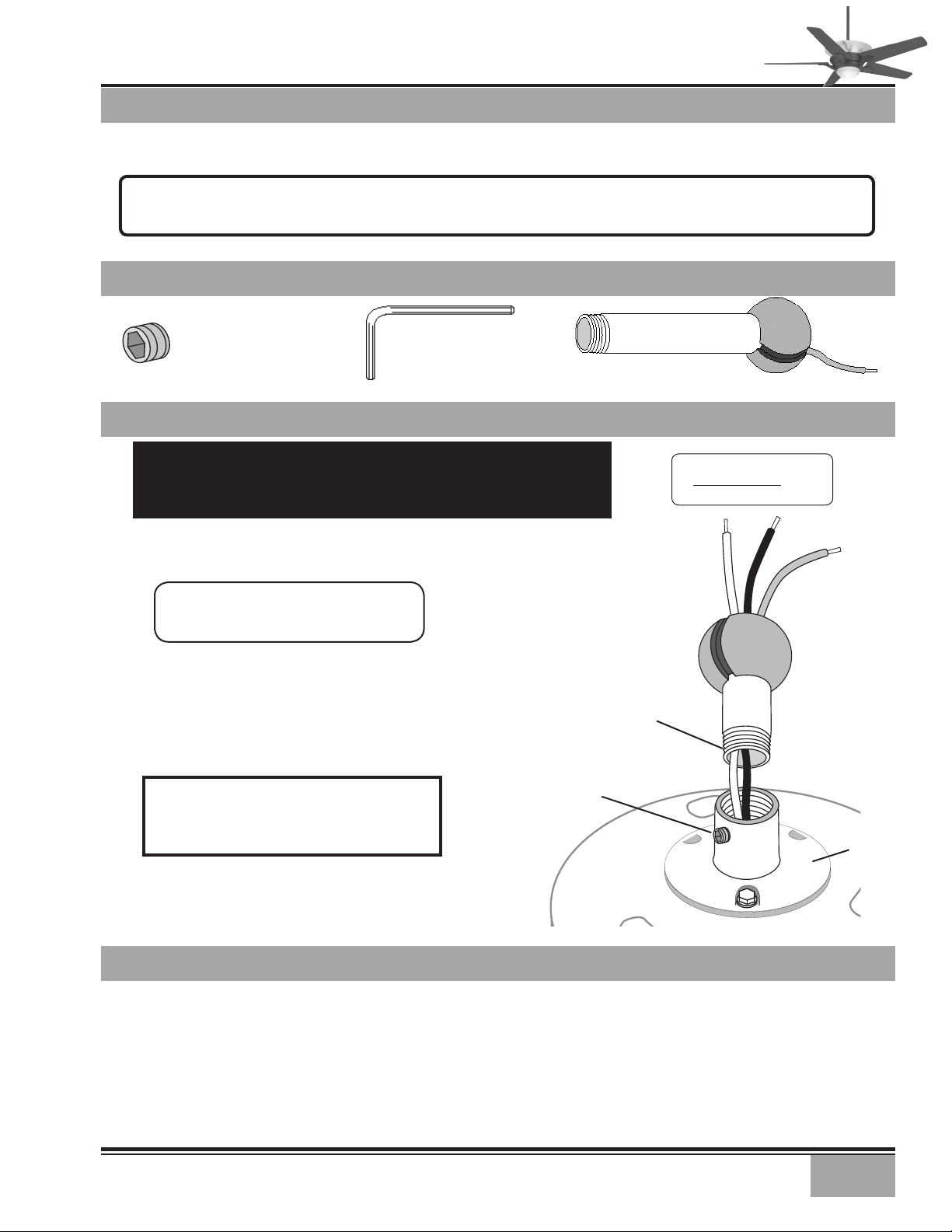
FAN PREPARATION
DOWNROD & BALL
ASSEMBLY
IMPORTANT SAFETY INFORMATION!
BEFORE STARTING THE INSTALLATION OF YOUR CEILING FAN, INSTALL THE
THREADED DOWNROD INTO THE MOTOR COUPLING AND LOCK THE ASSEMBLY
Prepare for fan installation as follows:
Step A. Route the wires from the motor through the
Perma•Lock™ downrod and ball assembly.
Tip: The downrod has a tapered thread
that is designed to lock completely when
correctly installed.
Step B. Using the provided allen wrench, loosen the set screw
several turns to allow installation of the downrod. Thread the
downrod into the motor coupling until it stops turning, this
will take at least four and a half full turns.
Step C. Securely tighten the set screw with the provided allen
wrench to ensure safe operation of your fan.
CAUTION: Failure to fully lock in the downrod before securely tightening the allen set
screw may cause the fan to separate from
the downrod during normal operation!
Dimensions: Weight:
Height 25.5 lbs
181/2”
MOTOR
WIRES
GROUND
WIRE
DOWNROD
& BALL
ASSEMBLY
TAPERED
THREAD
ALLEN
SET SCREW
MOTOR
COUPLING
GETTING STARTED
Installing a New Ceiling Fixture Outlet Box
If you do not have an existing fixture located where you wish
to place your Casablanca fan, an approved ceiling fixture
outlet box must be installed and wired.
Warning: To reduce the risk of fire, electrical shock,
or personal injury, mount to outlet box marked acceptable for ceiling fan support using the mounting
hardware provided with the outlet box.
Using Existing Ceiling Fixture Outlet Box
After turning the power OFF at its source (either circuit
breaker or fuse box), lower the old fixture and disconnect
the wiring. Check the ceiling fixture outlet box to be sure
that it is marked ‘Approved for ceiling fan mounting’. If it is
not, a new box must be installed.
3

CROSSBAR MOUNT-
ING BRACKET
SUPPORT INSTALLATION PARTS
CEILING HARDWARE
WIRE NUT (4)
ADDITIONAL HARDWARE
2
HEAD SCREW (2)
1” x 8-32 ROUNDED
HEAD SCREW (2)
1
/4” x 8-32 ROUNDED
FLAT WASHER (2)
LAG SCREW
3
/8” #7 X 5” (1)
CROSSBAR MOUNTING BRACKET INSTALLATION
Note: After removing the old fixture, check the outlet box
to insure that it is supported by a joist or beam across its
upper surface. If not, a 2” x 4” stud must be installed.
Step 1. Remove the knockout plug in the center of the outlet box or drill a
Then drill a
of 3″.
Step 2. Route the outlet box wires through the keyhole slot of
the crossbar mounting bracket as shown. Attach the crossbar
mounting bracket to outlet box with screws provided, assuring
that the outlet box wires are not pinched by the washer.
CAUTION: To reduce the risk of personal injury,
use only the mounting hardware provided with
the approved outlet box to install the crossbar
mounting bracket.
1
/2″ hole for the lag screw to pass through.
1
/4″ guide hole into the joist or beam to a depth
JOIST
CEILING FAN
APPROVED
WIRING BOX
CROSSBAR
MOUNTING
BRACKET
LARGE
FLAT WASHER
3
/8” (1)
CEILING
WIRING
RIDGE
SIDE
DOWN
4
WARNING!
SUPPORT DIRECTLY TO
BUILDING STRUCTURE ONLY.
FLAT
WASHER
APPROVED
OUTLET BOX
HARDWARE
GREEN
GROUND
WIRE
 Loading...