

CAS LP-II Owner's Manual

LP-II
Electronic Price Computing
Label/Receipt Printing Scale
REV: 3.00 Sep. 2006

Attention:
Copyright
reproduced, transmitted, transcribed, stored in a retrieval system, or translated into any
language or computer language, in any form or by any means, electronic, mechanical,
magnetic, optical, chemical, manual or otherwise, without the prior expressed written
permission of this company.
©
2006, by CAS Corporation. All rights reserved. No part of this publication may be
Disclaimer:
This company makes no representations or warranties, either expressed or implied, with respect
to the contents hereof and specifically disclaims any warranties of merchantabilit y or fitness for
any particular purpose. Any software describes in this manual is sold or licensed “as is”. Should
the programs prove defective following their purchase, the buyer (and not this company, its
distributors, or its dealers) assumes the entire cost of all necessary servicing, repair, and any
incidental or consequential damages resulting from any defect in the software. Further, this
company reserves the right to revise this publication and to make changes from time to time in
the contents hereof without obligation to notify any person of such revision or changes.
Brand and product names are trademarks and/or registered trademarks of their respective companies.

TABLE OF CONTENTS
PAGE
1 General
1.1 Model and Specifications............................................................................................................7
1.2 Dealers and Service......................................................................................................................8
2 Unpacking and Assembly
2.1 Box Contents..................................................................................................................................8
2.2 Assemb ly of Dis play Column.......................................................................................................9
3 Proper Operation
3.1 Environmental Considerations and Safety.............................................................................10
3.2 Leve ling and Location................................................................................................................12
3.3 Dont’s ............................................................................................................................................13
3.4 Cleaning and Maintenance .....................................................................................................14
3.5 Power Outlet Requirements ......................................................................................................14
4 Nomenclature
4.1 Scale Overview ...........................................................................................................................15
4.2 Display and Indicators................................................................................................................16
4.3 Printer.............................................................................................................................................17
4.4 The Sal es Mode Nu meric Key Pad Conf iguration .................................................................18
4.5 The Program Mode Numeric Key Pad Configuration...........................................................22
5 Quick Set-Up
5.1 Installation of th e Label Roll .......................................................................................................25
5.2 Basic Quick Start..........................................................................................................................28
6 Programming
6.1 Main Menu ....................................................................................................................................30
6.1.1 RPK: Repack Mode...................................................................................................................31
6.1.2 Stor e Settings..............................................................................................................................31
6.1.3 Stor e Name, Address, & Number............................................................................................31
6.1.4 Secur ity Con trol .........................................................................................................................32
6.1.5 Department Names..................................................................................................................34
6.1.6 Scale Assignments .....................................................................................................................35
6.1.7 Date and Time ...........................................................................................................................35
6.2 Settings...........................................................................................................................................36
6.2.1 Print Inhi biting.............................................................................................................................36
6.2.2 Sales Messages..........................................................................................................................37
6.2.3 Scrolling Message......................................................................................................................37
6.2.4 Scrolling Sequence ...................................................................................................................38
6.2.5 Tax Rates.....................................................................................................................................39
6.2.6 Labe l Types.................................................................................................................................39
6.2.7 Adjust Feed Length...................................................................................................................40
6.2.8 Origin...........................................................................................................................................41
6.3 PLU Programming.........................................................................................................................41
6.3.1 PLU Price Change .....................................................................................................................42
6.3.2 Creating PL Us.............................................................................................................................43
6.3.3 Renumbering PLUs.....................................................................................................................51
6.3.4 Listing PL Us ..................................................................................................................................51
iv

TABLE OF CONTENTS
PAGE
6.3.5 Copying PLUs ............................................................................................................................ 52
6.3.6 Edit PLUs.....................................................................................................................................52
6.3.7 Promotion/Frequent Shopper Program ............................................................................... 53
6.3.8 Deleting PL Us.............................................................................................................................54
6.3.9 Audit Trail PLUs .......................................................................................................................... 54
6.3.10 Speed Key Programmin g .....................................................................................................55
6.4 Self-Time Print Mode ................................................................................................................... 55
6.5 Global Settings ............................................................................................................................ 57
6.5.1 Global Label Format ............................................................................................................... 56
6.5.2 Frequent Shopper Discount Program...................................................................................56
6.6 Network Settings (optional)....................................................................................................... 59
7 Sale Modes
7.1 REG, MGR , and RPK Modes....................................................................................................... 57
7.2 REG Mode .................................................................................................................................... 60
7.2.1 ZERO Key.................................................................................................................................... 58
7.2.2 TARE Key ....................................................................................................................................58
7.2.3 lb/k g Key ................................................................................................................................... 59
7.2.4 ON/OFF Key ..............................................................................................................................59
7.2.5 PLU/SHIFT Ke y and Speed Keys.............................................................................................. 60
7.2.6 MISC P LU Keys........................................................................................................................... 60
7.2.7 FOR Key ..................................................................................................................................... 62
7.2.8 1/2, 1/4, and 100g Keys........................................................................................................... 63
7.2.9 CLEAR Key.................................................................................................................................64
7.2.10 ADD, VOID , and ST/TTL Keys.................................................................................................64
7.2.11 SAVE Key.................................................................................................................................. 65
7.2.12 AUTO/MAN UAL Key ............................................................................................................... 65
7.2.13 PRE- PACK Key.........................................................................................................................66
7.2.14 X Key ........................................................................................................................................66
7.2.15 RETURN Key ............................................................................................................................. 67
7.2.16 OVERRIDE Key......................................................................................................................... 68
7.2.17 DEPT Key.................................................................................................................................. 69
7.2.18 Temporary Dat e Change.....................................................................................................70
7.2.19 Temporary Dat e Print Inhibit ................................................................................................ 70
7.2.20 Temporary PLU Data C hange ............................................................................................. 71
7.3 MGR Mode................................................................................................................................... 74
7.4 RPK Mode.....................................................................................................................................75
8 X and Z Modes
8.1 Reading Sales Sumaries: X Mode............................................................................................. 73
8.1.1 PLU Sales....................................................................................................................................73
8.1.2 MISC P LU Sales..........................................................................................................................75
8.1.3 Group Sales............................................................................................................................... 75
8.1.4 Department Sales .................................................................................................................... 76
8.1.5 Scale Sales ................................................................................................................................ 76
8.1.6 Hourly Sales...............................................................................................................................77
8.1.7 Clerk Sales................................................................................................................................. 77
8.1.8 Summary Report......................................................................................................................77
8.2 Resetting Sales Summaries: Z Mode........................................................................................ 78
v

TABLE OF CONTENTS
PAGE
Appendix A; Country Codes...........................................................................................................81
Appendix B; Label Formats .............................................................................................................83
Appendix c: Quick Reference........................................................................................................86
Warranty .............................................................................................................................................88
vi
1 General
1 General
1.1 Model and Specifications
CHARACTERS PER PLU Ingredients: 2000 char. MAX, PLU Name: 114 char. MAX
PROGRAMMABLE DATA
MEASUREMENT TYPE LOAD CELL
MEMORY CAPACITY 4 MEGABYTES STANDARD
MEMORY OPTION N/A
SPECIFICATIONS
OPERATING TEMP. -10° C~ 40° C (14° F~ 104° F)
PLU PROGRAMMABLE
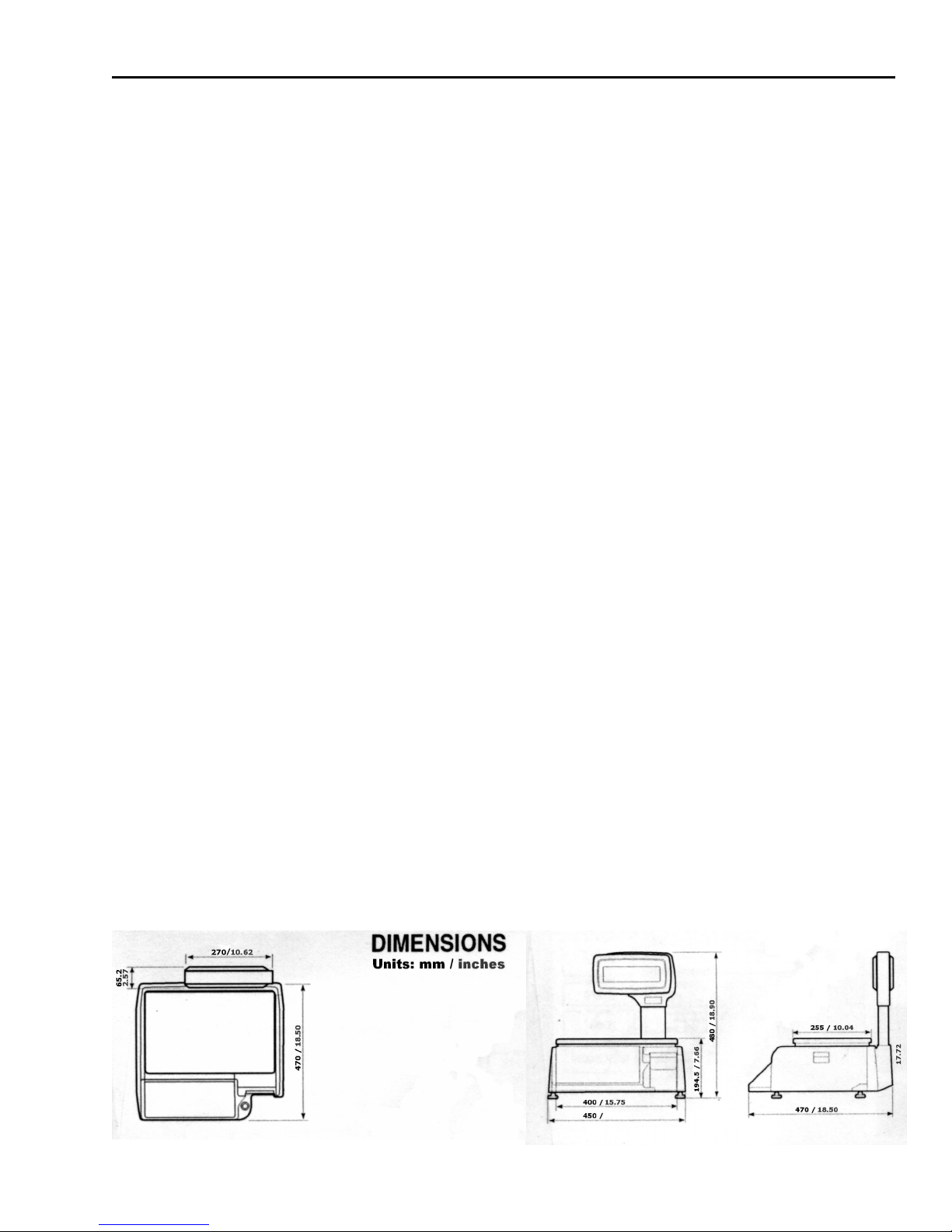
PLATTER SIZE Length: 403 mm (15.87 in.), Width: 260 mm (10.24 in.)
POWER SOURCE 85~240VAC 50/60Hz ±5%
PRINTER TYPE DIRECT THERMAL PRINT
SALES PERIODS Dual totals for daily/monthly or user selectable reporting periods.
SALES REPORT MODES Read: X1/X2 Modes, Read & Reset: Z1/Z2 Modes
SALES REPORT TYPES Daily PLU & Misc. PLU Report
SHIPPING WEIGHT 13 kg (29 lb)
WEIGHING CAPITY 0~15 x 0.005 lb / 0~30 x 0.01 lb
WEIGHING RANGE DUAL RANGE
WEIGHING UNITS Pound & Kilo push-button selectable.( Only USA version )
MODEL LP-2, (version 2.25)
DISPLAYS WEIGHT: 5 digits (5 max)
GENERAL
INTERFACES RS-232, Wired Ethernet(RJ45), Wireless Ethernet(IEEE 802.11b)
LABEL SIZES Width: 10mm~80 mm (0.40 in.~3.15 in.)
MAX TARE FULL CAPACITY
NETWORK
DATA
PRINT SPEED 100 mm/sec (4 in./sec)
UNIT PRICE: 6 digits (8 max)
TOTAL PRICE: 7 digits (9 max)
Scrolling Messages : 32 @ 80 Char
Sales Messages : 32 @ 40 Char
Store Name : 150 Char
Departments : 32 @ 20 Char
Length: 20mm~170 mm (0.94 in.~6.69 in.)
Length: 850 mm (33.46 in.) max length using linked formats.
10/100MB ETHERNET
W/ WIRELESS CABILITY OPTIONAL
Department # : 1~32
PLU # : 1~999999
Commodity Name : 114 Char
Label Format # : 1~999
Sales Message # : 1~32
Unit : lb, kg
Group Code : 0~99
Tax Rates : 0~3
Country Code : 0~999
Sell By Date : 0~999 days
Cook By Date : 0~999 days
Frequent Shopper/Discount Feature
Monthly PLU & Misc. PLU Report
Daily Department Report
Daily Scale Report
Daily Group Report
Daily Hourly Report
Daily Detailed Report
0~30 x 0.01 lb / 30~60 x 0.02 lb
(0~6 x 0.002 kg / 0~15 x 0.005 kg, 0~15 x 0.005 kg / 15~30 x 0.01 kg
Monthly Department Report
Monthly Scale Report
Monthly Group Report
Monthly Hourly Report
Monthly Detailed Report
Users/Clerks : 99 @ 20 Char
Label Formats : 999 @ 30 Char
Label Formats : Over 50 Built-In
Origin : 400 @ 25 Char
Tare Weight : 0~Capacity
Price : 0.00~9999.99
Sale Weight : 0~Capacity
Sale Price : 0.00~9999.99
Net Weight : 0~99999
Count : 1~99
Sale Count : 0~99
UPC : 0~999999
Ingredients : 2000 Char
Origin : 25 Char
Barcode Type/Format
Nutritional Information
Clerk Report
7

1 General
Note: Specifications are subject to change without notice.
1.2 Dealers and Service
1) Our Dealers: CAS Corporation is committed to offer the best products and the best service. To
offer the best products, CAS manufactures all of its products using only the best components
available and thoroughly tests all of its products to assure a maximum level of quality and
dependability. CAS feels that each of its valued customers should get the best service available.
Whether it’s the initial installation of our product, maintenance/repair work, or simply answering
questions about our products, CAS Corporation and all of its Authorized Dealers are highly trained
to assist you with any need regarding CAS products.
2)
Our Service: CAS (USA) offers service and support to all of its US products through its vast net work
of Authorized Dealers. If you cannot find or are unaware of any CAS Authorized Dealers in your
area, please visit us on the web at www.cas-usa.com. We will help you locate the CAS Authorized
Dealer nearest you.
3)
Dealers and Service: The CAS family of Authorized Dealers is always ready to assist you. Should
you need warranty service, supplies, or even have some questions about our products, don’t
hesitate to call on us! Remember that your first contact should always be the local CAS Authorized
Dealer whom you purchased the product from. He is best able to quickly help you with any
problem or question you should have regarding our product. CAS Authorized Dealers have a vast
library of documentation, stock of replacement parts and supplies, and all of the training needed
to assist you. Whether it’s help programming or maintaining your CAS products, CAS Aut horized
Dealers are always ready to assist!
Thank you again for making CAS your choice!
8
2 Unpacking and Assembly
2 Unpacking and Assembly
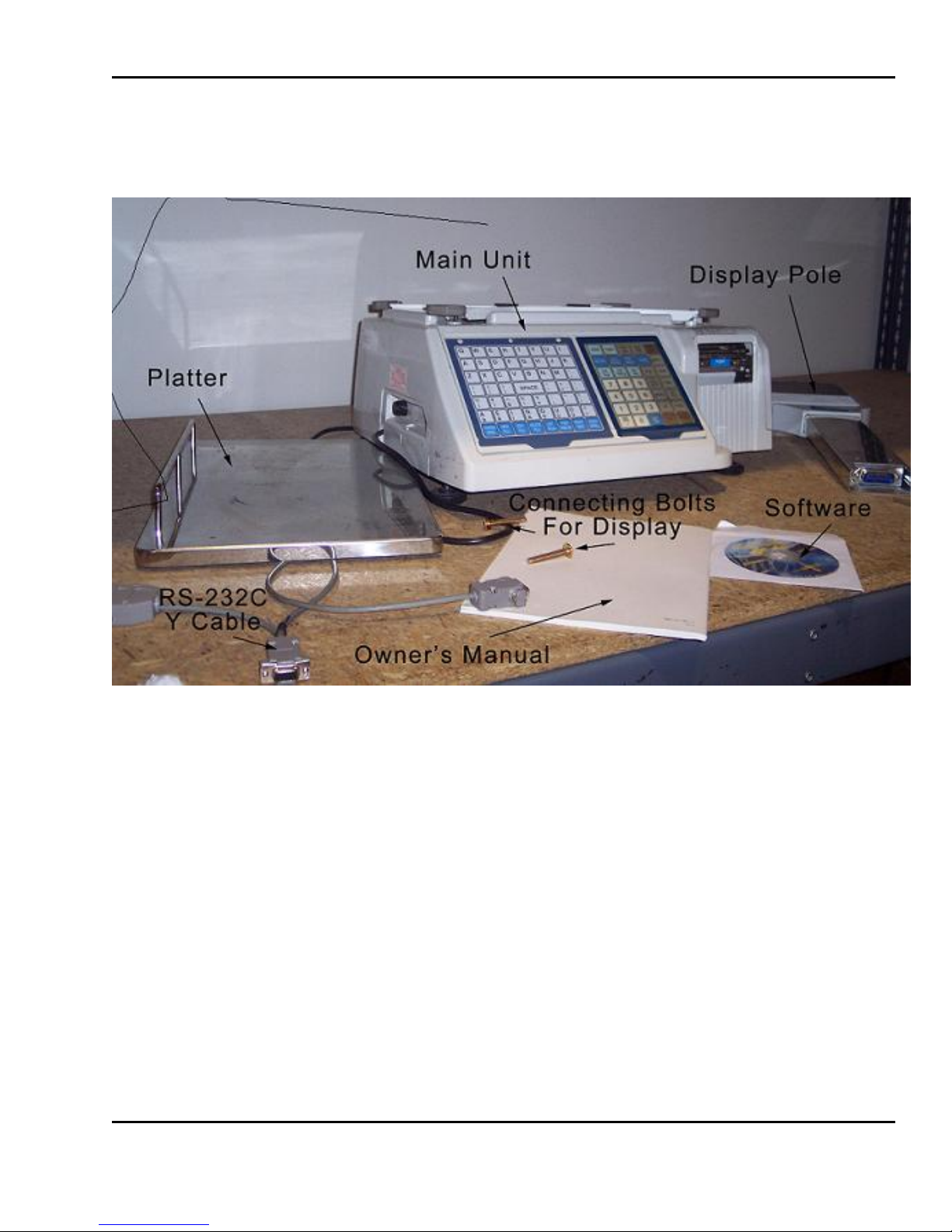
2.1 Box Contents
Pictured above are the contents that come with the LP-2. The scale comes with one roll of LST-8010
labels already installed and ready to use. It also comes with the software which can be used to
program the scale using the RS-232C cable, which is also included. It is important to note that the RS232 cable is a Y cable, with 3 connections. The 25 pin connector is no longer used, but is included for
possible future use. The scale also comes with a tear bar (not pictured) which is used for continuous
strip labels. A CAT-5 or Ethernet crossover cable, which can also be used to connect to a PC can be
purchased from your authorized CAS dealer.
9
2 Unpacking and Assembly
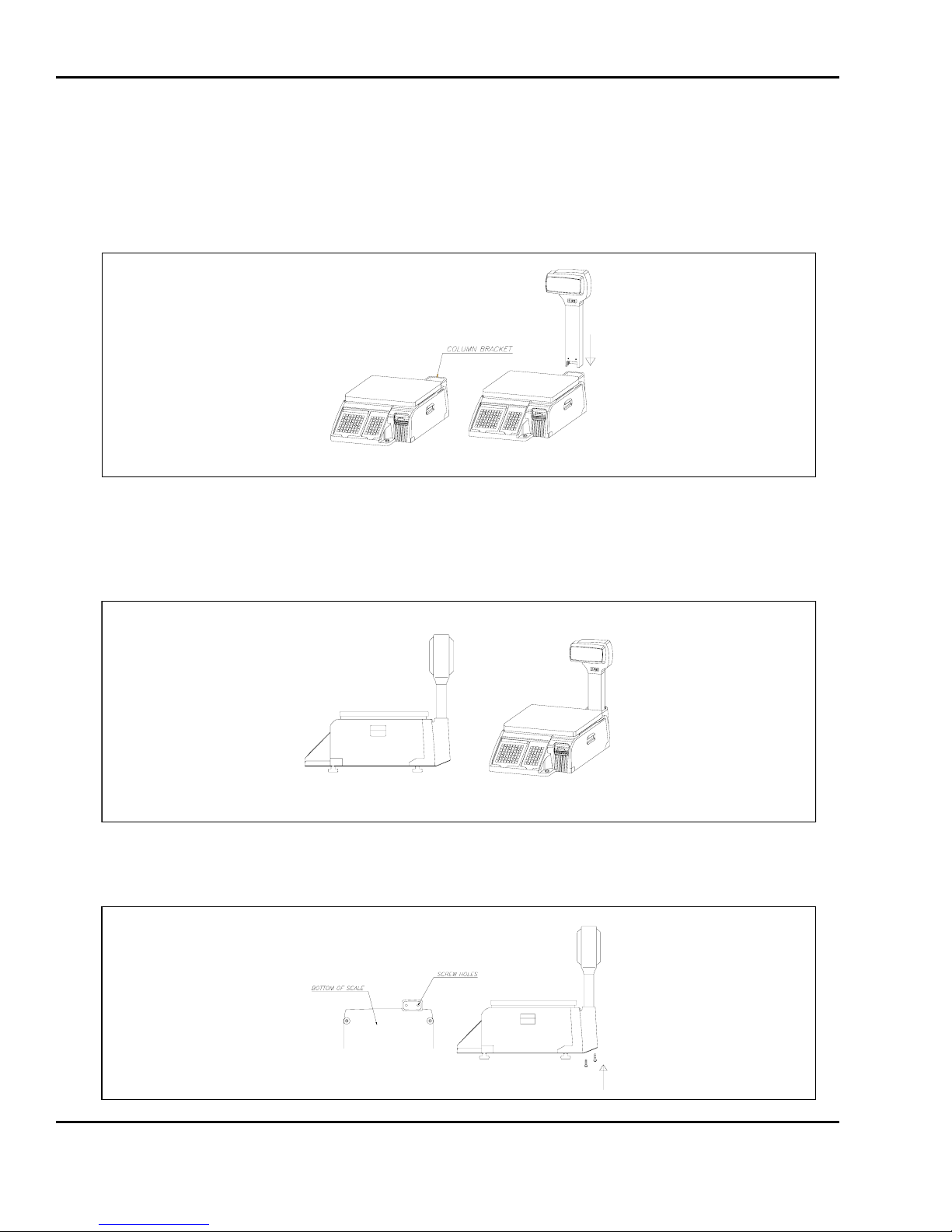
2 .2 Assembly of Display Column
1) You mu st follow the instructions in this sect ion in order to assemble the Display Assembly properl y. To
begin the installation, make sure that the scale is unplugged from any electrical source. Your scale
body has a display column bracket in the rear that the display column slides into. (See fig.)
2) Hold the display assembly in front of you such that the display assembly forms the figure “7”. Next,
with the scale’s keyboard facing you, insert the display column into the display bracket. When the
display column reaches the bottom of the display bracket, you will “feel” the connectors “snap”
together. (See fig.)
3) Underneath the display bracket you will find 2 screw holes for the display assembly screws. Insert
and fasten the 2 display assembly screws. You are done! (See fig.)
10

3 Proper Operation
3 Proper Operation
3.1 Environmental Considerations & Safety
1) Please avoid the following hostile conditions:
Temperatures below or exceeding:
-10º C ~ 40º C (14º F ~ 104º F)
Excessive vibration Unstable or flimsy surface
Wi nd or fans functioning in direct
contact with weighing platform.
Direct sunlight Dust or dirt
High humidity Poor ventilation
2) Environmental Protection: The scale should be installed in a dry and liquid free environment. When
the scale is installed in a high humidity or wet-type environment, be sure to avoid spilling or spraying
directly on any surface of the scale.
3) Personal Safety: It is extremely important to be aware of personal safety whenev er maintaining or
operating this equipment. Wherever possible, we have tried to place warning labels and other
indicators at the actual location on the equipment where the danger is most likely to occur.
However, it is not always possible to foresee all dangerous sit uat ions. Warnings and cautions that are
necessary for the safe operation of the scale are contained in this manual. Please, make sure to
carefully read ALL warnings and cautions before operating the scale.
4) Observe the following safety precautions:
Shut the scale OFF and unplug the scale whenever you are changing the label
roll or whenever working in the printer bay.
The outlet that the scale is plugged into, should be properly grounded.
Whenever connecting or disconnecting ANY cables from the scale, be sure to
hold the cables by the end connector. Failure to do so may cause a short
circuit.
Maintain a static free work area.
Never use any other equipment on the same line: it should be a dedicated line.
The outlet used must have the proper voltage ratings.
Ungrounded electrical outlet
Shared electrical outlet
11
3 Proper Operation
3.2 Leveling and Location
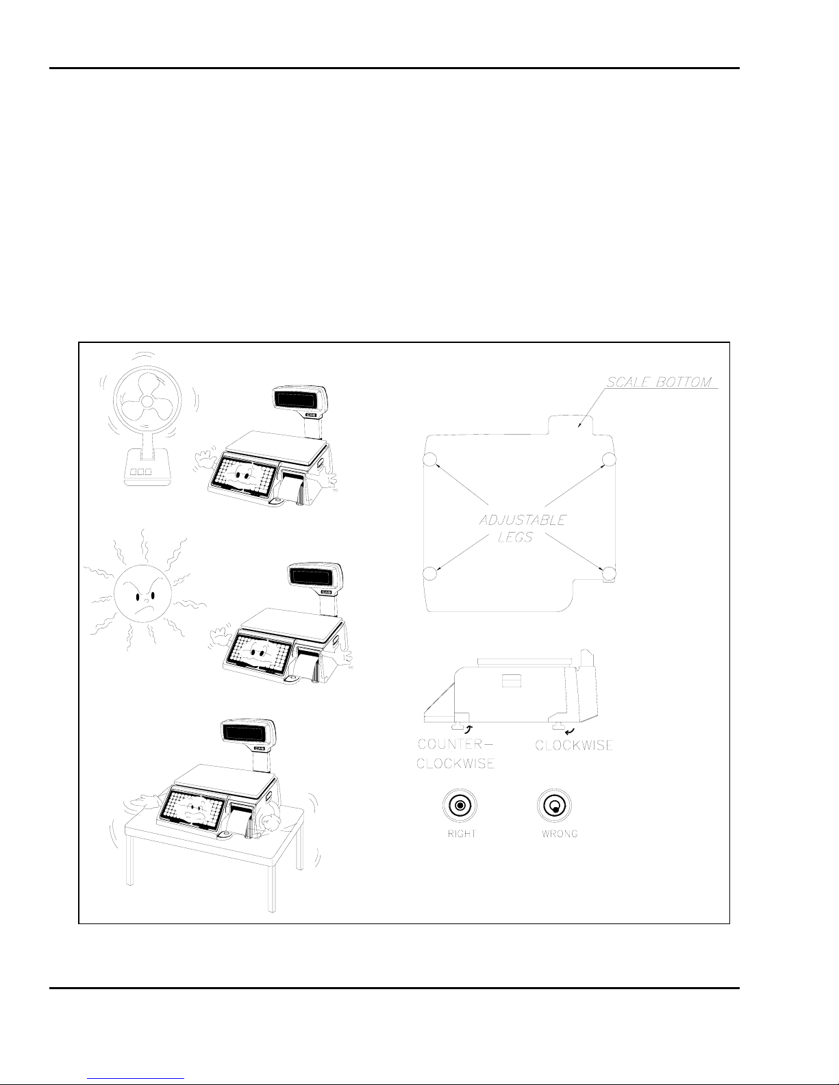
1) Location: This scale must be placed on a flat and stable surface. Please keep the scale away
from the direct path of oscillating fans, vent ilation systems, or strong drafts as these air disturbances
can be picked-up by the scale’s very sensitiv e weighing platform and may cause incorrect weight
readings.
2) Leveling: If the scale is not properly leveled, please adjust the 4 adjustable legs at the bott om of
the scale. Turn the legs clockwise or counterclockwise so as to center the bubble of the leveling
gauge inside the indicated circle. Turning t he adju st abl e legs count er-cl ockwise (viewed from top of
scale) will lower that part of the scale. Turning the adjustable legs cl ockwise (viewed from top of
scale) will raise that part of the scale. (See Fig.)
12

3 Proper Operation
3.3 Don’ts
DO NOT subject the platter to sudden shocks.
DO NOT drop anything on the platter.
DO NOT store any thermal labels where they may be subject to:
direct sunlight
high humidity
high temperature
dust.
DO NOT press the keys excessively hard. The keys will operate
correctly if they are pressed lightly. If any keys fail to work, contact
your Authorized CAS Dealer.
DO NOT hold or attempt to carry the scale by the Pole Display.
DO NOT pour water or ANY liquid directly on the scale.
DO NOT use any label media that is not recommended by CAS Corp.
DO NOT attempt to effect repairs to this equipment. Doing so is
against the law in most states. If any fault occurs that cannot be
rectified using this manual, unplug the scale and contact you
Authorized CAS Dealer.
13

3 Proper Operation
3.4 Cleaning and Maintenance
1) The LP-2’s exterior should be cleaned with a damp cloth and a mild soap solution. Do not spray
any chemicals directly onto the LP-2. Always spray any cleaning liquids onto t he cloth rag you are
using to wipe the scale clean. Remember NEVER to hose-down the scale. Before doing any type
of cleaning, always make sure that the scale is turned OFF using the side COM Port Access Panel
ON/OFF switch. Using the keyboard’s ON/OFF switch is NOT enough.
The keyboards should be cleaned with a damp cloth rag soaked in a mild soap solution.
Never spray water or any liquid directly on to the keyboard as these may cause damage to the
keyboard’s seal and then further damage individual keys. DO NOT use solvents, harsh, or abrasive
chemicals or cleaning devices as these may discolor and even completely remove the trim paint
on the keyboards. If you require more thorough cleaning, contact your local Authorized CAS
Dealer for service.
The displays should be cleaned with a damp cloth rag soaked in a mild soap solution.
Never spray water or any liquid directly on to the displays as these may cause damage to the
display’s seal and possibly short out the scale’s electronic components. Also, these displays use
very high voltages so special care should be taken never to wet them. DO NOT use solvents, harsh,
or abrasive chemicals as these may discolor and even completely remove the wording on the
displays. If you require more thorough cleaning, contact your local Authorized CAS Dealer for
service.
2) To clean the LP-2’s platter, please make sure that the scale is turned OFF using the side COM Port
Access Panel ON/OFF switch. Using the keyboard’s ON/OFF switch is NOT enough. First, remove
the platter from the platform and place it in a large tub or sink. You can wash it down with soap
and high-pressure water and/or hot water. Before replacing the platter on the platform, make sure
that it is completely dry.
3) The printer compartment also needs cleaning; however, this process requires more careful
cleaning. There are many sensitive parts as well as moving parts in the printer bay. Whenever
doing anything in the printer bay, please make sure that the scale is turned OFF using the side
COM Port Access Panel ON/OFF switch. Using the keyboard’s ON/OFF switch is NOT enough.
To begin, turn the scale OFF via the ON/OFF switch located on the left side of the scale in
the COM Port Access Panel. Next, open and remove the Printer Side Access Panel. With a small
brush or toothbrush, remove all of the debris that has accumulated on the base of the printer bay.
DO NOT attempt to remove any dirt or debris from anywhere else in the printer bay area. If you
require more thorough cleaning, contact your local Authorized CAS Dealer for service. If you
attempt to effect cleaning of other printer parts yourself, you risk damage to components or even
electrical shock regardless of the scale’s ON/OFF status.
4) The thermal print head also requires cleaning. It is recommended to clean the thermal print head
every time you replace the label roll. You can clean the thermal print head with a cotton swab
dipped in either a mild soap solution or isopropyl alcohol.
14
3 Proper Operation
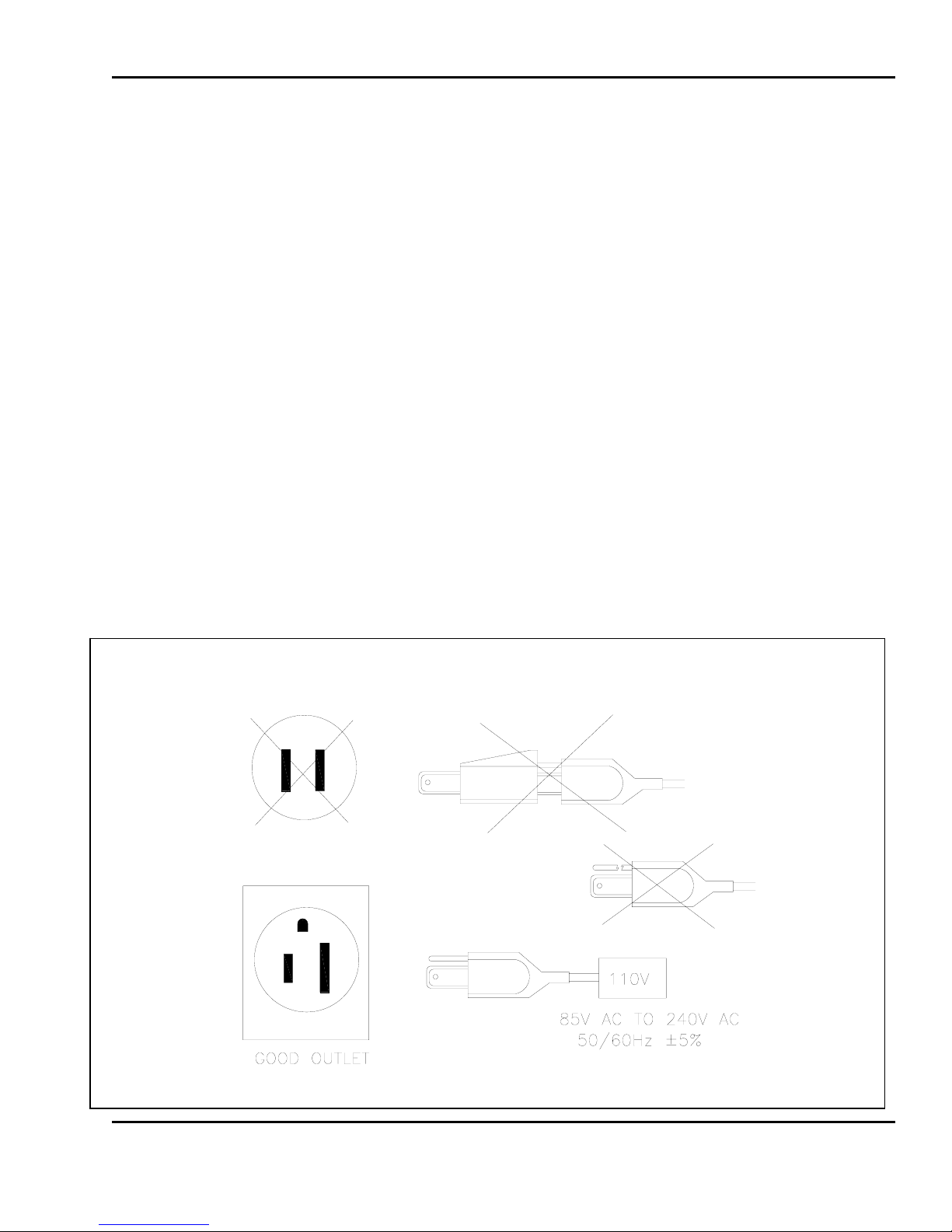
3.5 Power Outlet Requirements
The LP-2 is designed to be used almost anywhere in the world! Like the many appliances of today,
the LP-2 is designed with an automatically switching power supply. This allows operation when
connected to an AC source from 85V to 240V at 50/60Hz with 5% tolerance.
Remember: a switching power supply does not imply that bad, noisy, or improperly wired power
lines will be problem free. With that in mind, please make sure that the power lines used for the LP2 are dedicated lines with no high-noise devices (such as compressors, motors, etc) running on it.
Also, make sure that the wiring to the electrical socket is correct. If you are uncertain as to the
state of your business’ electrical lines, please contact a certified electrician.
1) Once you are sure as to the safety of the electrical line, make sure to ONLY plug the scale into a 3prong outlet. The third prong is a safety ground and an electrician should properly wire t his if it is
not correct or if you are unsure. Failure t o this CAN result in el ectrical shock from use of this or any
electronic scale.
2) Do not use any 3-prong to 2-prong adapters or break-off the third prong from the LP-2 power cord.
The third prong is necessary and must be properly connected.
3) If you have any problems or questions regarding this matter, make sure to consult an Authorized
CAS Dealer or an electrician.
15

3 Proper Operation
Note: Be sure to check the LP-2’s serial number plate on the back of the scale for power specifications.
16
4 Nomenclature
4 Nomenclature
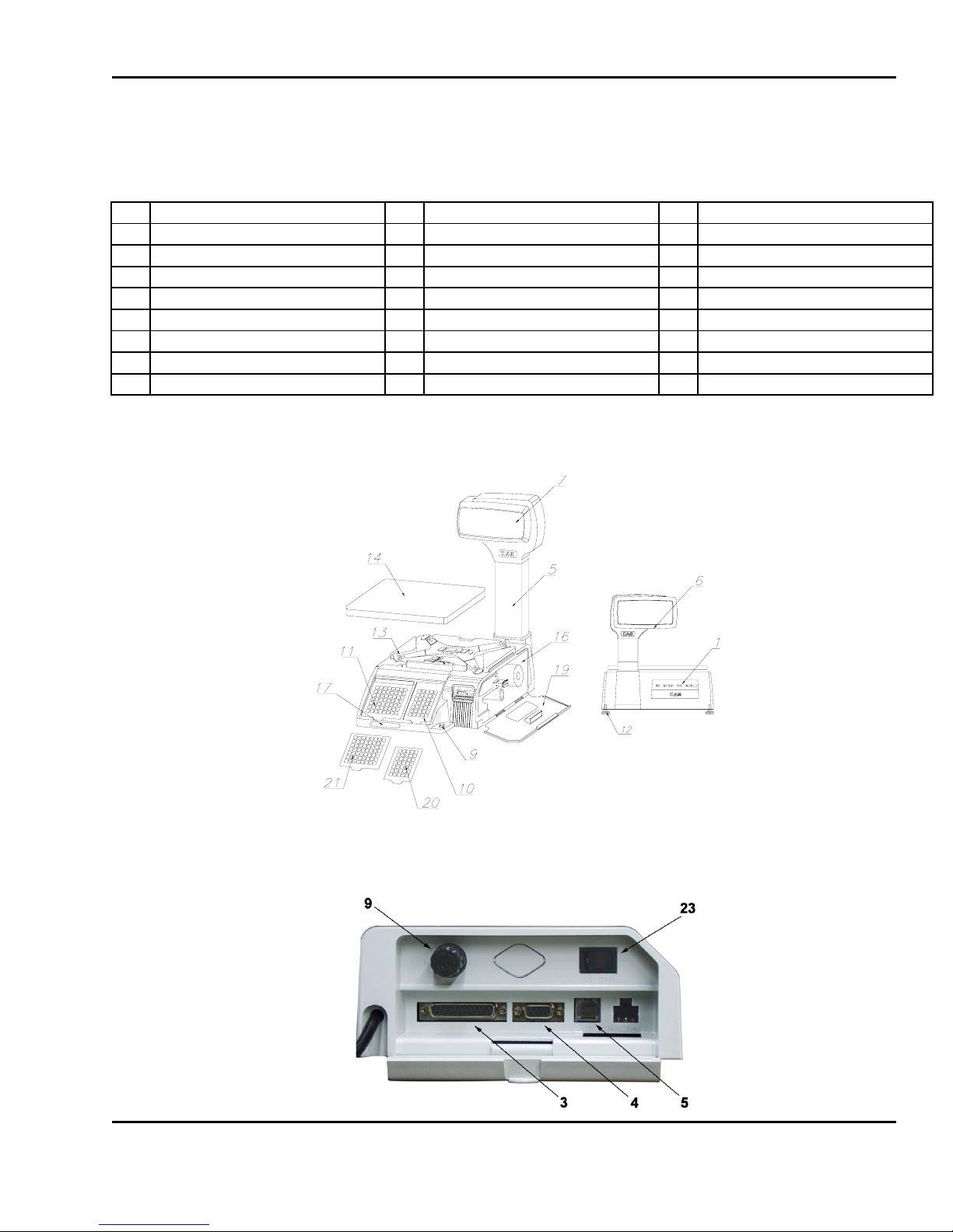
4.1 Scale Overview
Pictured Below are some parts you should be familiar with
# Description # Description # Description
1 Advertisement Insert, rear 9 Fuse Cap 16 Power Switch
2 Wireless Bridge Connector 10 Gauge, Leveling 17 Printer
3 RS-232C 25 Pin Connector 11 Keyboard, Numeric 18 Serial Number Plate
4 RS-232C 9 Pin Connector 12 Keyboard, Speed Keys 19 Side Access Door, Com port
5 Ethernet Connector 13 Leveling Feet 20 Side Access Door, printer
6 Display Column 14 Platform 21 Template Sheet, Numeric
7 Display Window, customer 15 Platter 22 Template Sheet, PLU
8 Display Window, user 23 Power Switch
17
4 Nomenclature
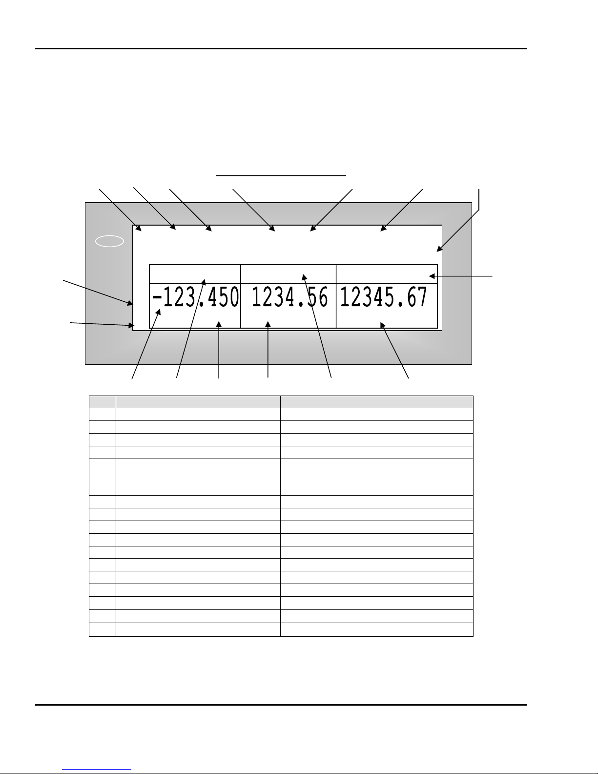
4.2 Display and Indicators
1) VF Display: The front and rear displays on the LP-2 are dot matrix vacuum fluorescent displays.
They will display all information pertinent to operating the scale.
LP-2 Display Window: Sales
1 2 3 4 5 6 7
III
16 8
ZERO
STABLE
15
14 13 12 11 10 9
# Description Values
.10 Unit price heading UNIT, money and weigh symbols
11 Unit price indicator 6 digits USA: 0.00~999.99
12 Weight indicator 5 digits
13 Weight heading WEIGHT and weigh symbol
14 Negative weight indicator -, (Blank)
15 Net-Weight indicator ◀, (Blank)
16 Stable weight indicator ○, (Blank)
17 Zero weight indicator ◀, (Blank)
A Gross Zero indication is reached when the Net-Weight indicator is OFF, the Zero-Weight indicator is
ON, the Stable indicator is ON, and the weight reads 0.00 or 0.000.
<REG> Auto PrePack Shift Ride 12:12:00 PM
This is PLU COMMODITY
WEIGHT lb
◀
○
NET
1 Mode indicator REG, RPK, MGR, ADD, NET1, STR2,
2 Print Mode indicator Auto
3 Auto Clearing status indicator PrePack, Save, (Blank)
4 Speed key Shift status indicator Shift, (Blank)
5 Override & Discount Status Ride, DISC, Disc,FSP)
6 Multi-function indicator
7 PLU Description line
8 Total price heading TOTAL PRICE and money symbol
9 Total price indicator 7 digits USA: 0.00~9999.99
◀
0~30 lb x 0.01 lb / 30~60 lb x 0.02 lb, e=d=0.01 lb, 0.02 lb
0~15 kg x 0.005 kg / 15~30 kg x 0.01 kg, e=d=5g, 10g
UNIT $/ lb
Time, date, scale #, department #,
Alt, Temporary Changes, (Blank)
First non-blank line of PLU commodity
TOTAL PRIC
18
E $
4 Nomenclature
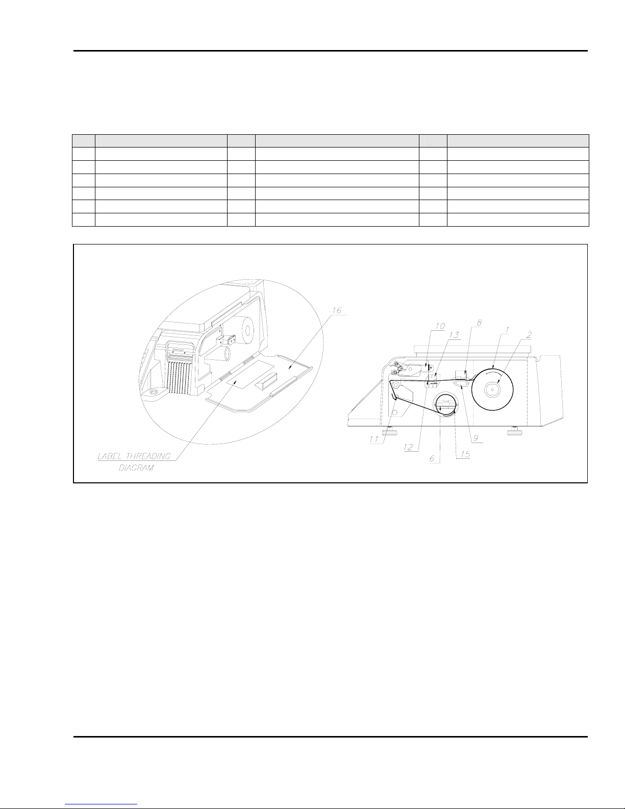
4.3 Printer
1) Pictured below are important printer components and parts that you should be familiar with.
# Description # Description # Description
1 Label/Paper Roll 7 Pin, label roll 13 Sensor Assembly, Gap
2 Label Roll Spool 8 Platen 14 Sensor Assembly, Peel-Off
3 Lock-Down Tab 9 Pressure plate & width adjuster 15 Shaft, Pick-Up Motor
4 Paper Cutter 10 Release Lever, TPH 16 Side Access Door, printer
5 Peel-Off Bar 11 Roller, return 17 Thermal Print Head
6 Pick-Up Spool Assembly 12 Roller, width-adjusting
To clean the Thermal Print Head, turn the scale OFF. Open the printer’s side-access door and release
the print head using the release lever. Use a clean cloth, moistened with a non-abrasive cleaning
solution to gently clean the underside of the printhead, NEVER insert a metal object such as a
screwdriver or knife under the printhead.
19
4 Nomenclature
g
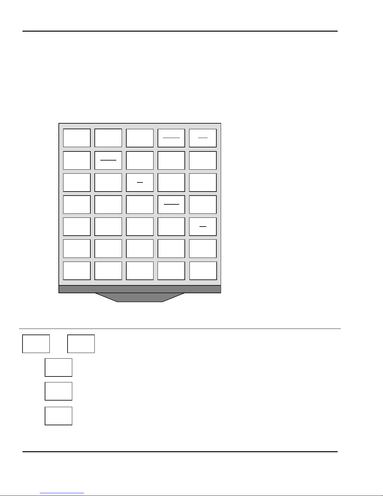
4.4 The Sales Mode Numeric Key Pad Configuration ( USA )
0
ZER
RETURN
4
1
00
.
Key Description
~
00
.
C
9
ZER
TARE
AUTO
MANUAL
1/2 1/4
2 3
0 C
Numeric keys. Used to enter pricing, qty, count, tare, etc.
Double zero key.
Clear key. Used to clear erroneous entries and error conditions. This key can
use to stop printing of label.
Re-Zero key. Use to remove small variations in the scale’s zero.
OVERRID
PRE-PACK
lb
k
9 8 7
6 5
DATE
TIME
SAV
FOR
PLU
SHIFT
MENU
X
ALT
ON
OFF
DEPT
VOI
ADD
ST
TTL
FEED
PRINT
20
4 Nomenclature
g
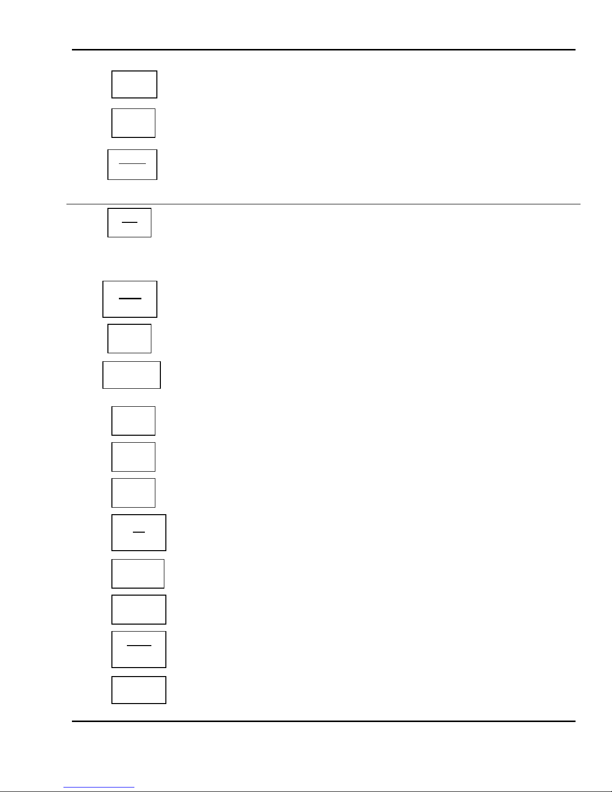
TARE
OVERRID
DATE
TIME
Key Description
ON
OFF
AUTO
MANUAL
PRE-PACK
SAVE
DEPT
1/4
Tare key. Use to manually enter and remove tare weights.
Override key. For temporary price change entry.
In REG, requires a level 2 password. In MGR, RPK no password needed.
Date & Time key. Toggles the display between time, date, scale number,
department number, and clerk name. Also does temporary date changes.
In REG, requires a level 2 password. In MGR, RPK no password needed.
ON / OFF key. This key turns the display on or off; however, the rest of the
scale remains powered. Also does temporary D ATE Print In hibit chan ge
Return key. Used to credit sales for erroneous transactions or returns.
In REG, requires a level 2 password. In MGR, RPK no password needed.
AUTO/MANUAL key. Toggles between Auto-print mode and Manual mode.
Pre-Pack key. Used to enter Pre-Packaging mode in which the scale Autoprints for every transaction and prevents the auto clearing of data.
Save key. Save mode prevents the auto clearing of any called-up data like
tare weight, PLU pricing, etc.
Department key. For temporarily selecting PLUs from other departments.
In REG, requires a level 2 password. In MGR, RPK no password needed.
1/4 pound key. In lb mode this key is used to multiply unit prices by 4.
1/2
Lb
k
FOR
VOID
PLU
SHIFT
ADD
1/2 pound key. In lb mode this key is used to multiply unit prices by 2.
lb/kg key. Use this key to switch from pound to metric weighing.
For key. Use this key for by-count pricing: 3 @ 3 FOR $1.00. It toggles
between the QTY, PIECE, and PRICE fields of by-count picing.
Void key. To remove erroneous sales from ADD-Up or Receipt sales only.
PLU and SHIFT key. When you type a PLU number and press this key, it callsup that PLU. Simply pressing the key will change the PLU shift status.
ADD-Up key. This key when used in conjunction with ST/TL key allows you
print a customer-total label as well as individual transaction labels.
21
4 Nomenclature
R
MENU
ST
TTL
X
MENU key. This key toggles from Main menu to <REG><MGR><RPK> mode.
Subtotal / Total key. Us ed with the AD D key in order to print customer-totals.
Multi-Label key. Use this key to print multiple sales of the same transaction &
is also used for selecting the displayed currency.
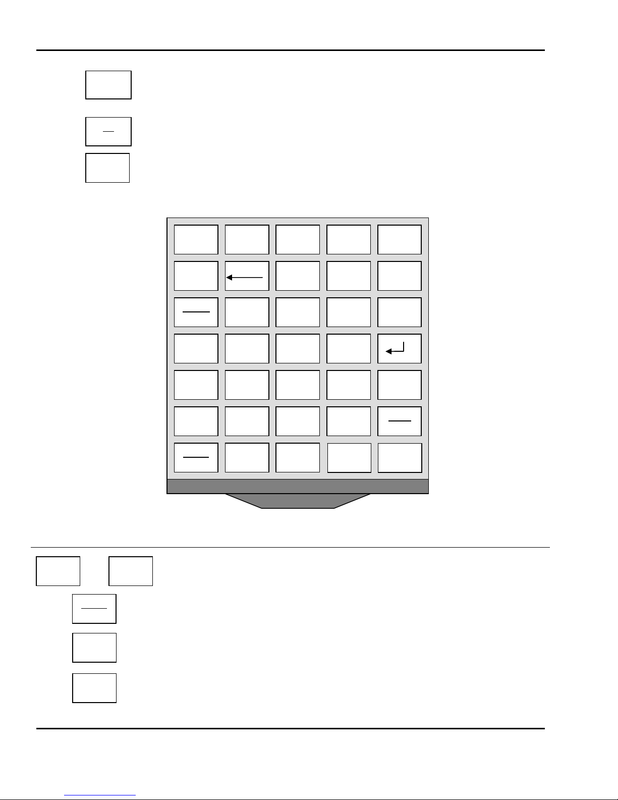
4.5 The Program Mode Numeric Key Pad Configuration
Key Description
0
~
00
.
C
9
COPY
O
L
INSERT
OVE
7
4
1
00
Numeric keys. Used to enter programming data.
Decimal key.
Clear key. Used to clear erroneous entries and error conditions
Copy key.
P
BACK
SPACE
8
5
2
0
COPY
◀
PASTE DELETE
9
6
3
C
▲
SAVE
▼
SHIFT
ESC
TEST
ALT
PAGE
UP
▶
PAGE
DOWN
HELP
LABEL
FEED
ENTER
22
4 Nomenclature
▼
▶
R
▲
◀
PAGE
UP
A
BACK
SPACE
Key Description
PAGE
DOWN
INSERT
~
OVE
Z
SAVE
ENTER
DELETE
PASTE
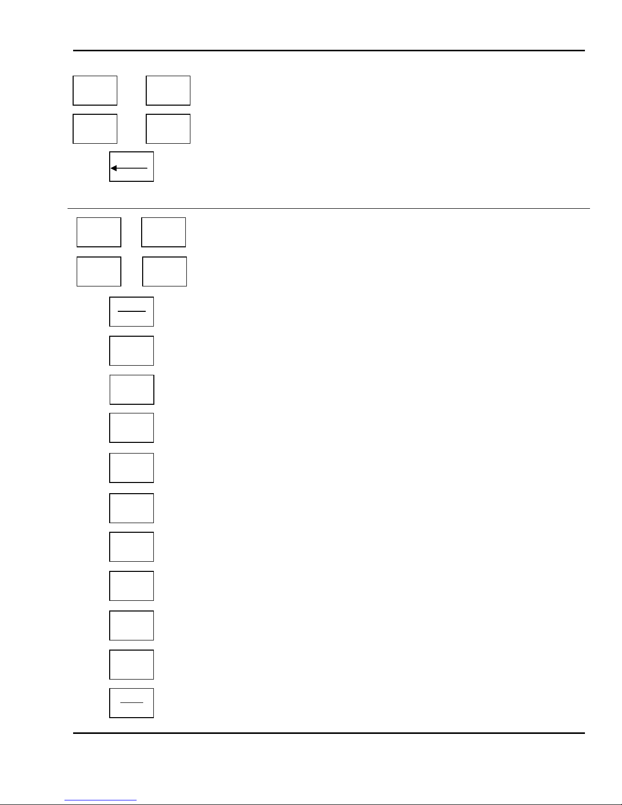
Up & Down arrow keys. Use to navigate through PGM mode.
Left & Right arrow keys. Use to navigate through PGM mode.
Backspace key. Used to backspace and delete text data.
Page Up & Page Down keys. Use these to navigate 1 screen at a time.
Alpha keys. Used to type text data.
Insert/overwrite key. Used to toggle between Insert and overwrite modes for
text typing.
Save key. At any point in programming, this key saves your current data.
Enter key. Used as an ENTER key.
Delete key. Used to delete tex t data.
Paste key.
ALT
SHIFT
ESC
HELP
TEST
LABEL
FEED
ALT key. This key is used for special key combination presses.
SHIFT key. This is the Caps Lock key. It controls whether you are typing in
uppercase .
Escape key. This key toggles between Main menu and <REG> mode. It also
is used to exit programs.
Help key. When the screen displays the word of “help”, you can see help
message by pressing ‘HELP’key.
Test key. Used to print test pattern, preview a scrolling message, and print a
PLU verification label.
Label Feed key. Use this key to feed labels or paper through printer.
23
4 Nomenclature
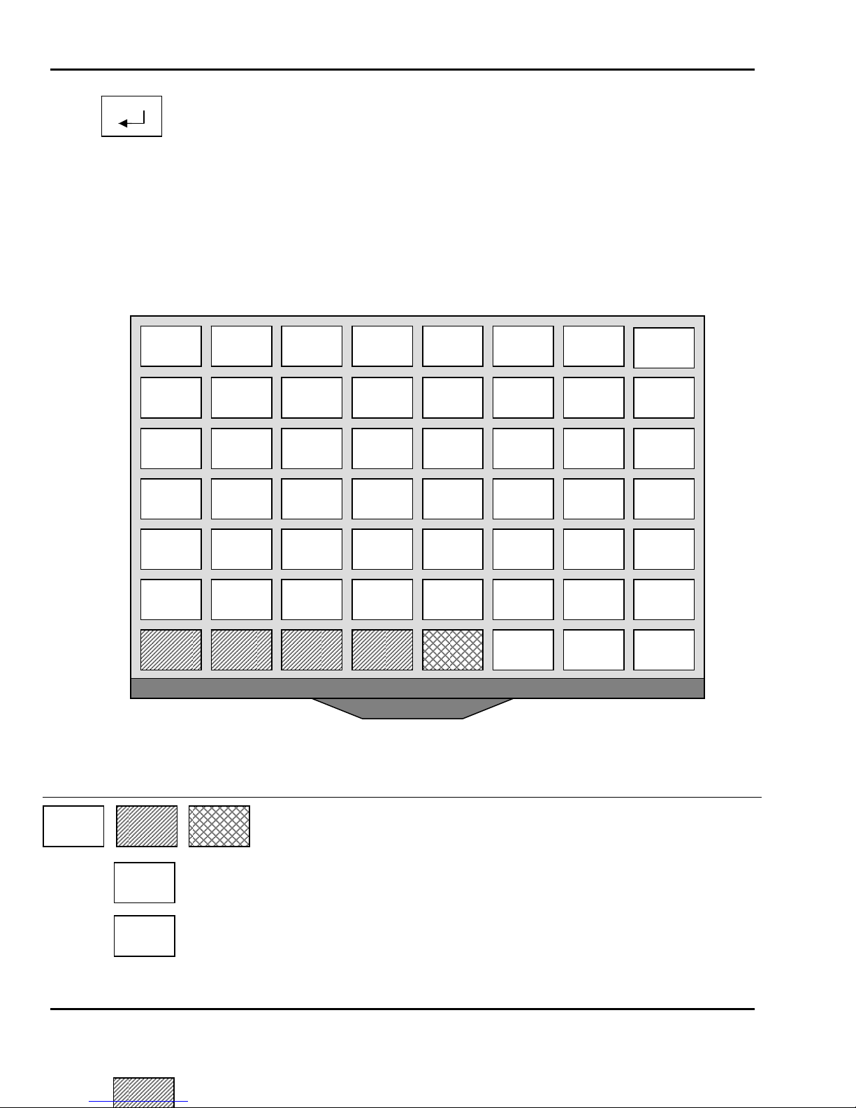
Carriage Return key. This key is used to insert Carriage Returns into the Text
1, 2, & 3 fields of PLU Create/Edit.
The Sales Mode PLU Key Pad Configuration
Weighed
By-Count
Key Description
MISC.
MISC.
All of the keys on this keyboard can be Speed keys in Non-Floating
Clerk mode. Used to call-up PLUs quickly.
Miscellaneous Weighed PLU key.
If disabled this key works like any other Speed key.
Miscellaneous By-Count PLU key.
If disabled this key works like any other Speed key.
Weighed
MISC.
MISC.
By-count
MISC.
Non-food
24

4 Nomenclature
ì
Y
A
/
;
MISC.
Non-Food
Miscellaneous Non-Food PLU key.
If disabled this key works like any other Speed key.
In Floating Clerk mode, only this blank keys can be Speed Keys.
Clerk-Speed keys for Clerks 1 to 4 numbered from left to right. And last 5
numbered key is the Clerk Select key
Floating Clerk mode 1 Only
CLERK key for selecting clerks 5 through 99.
Floating Clerk mode 1 Only
The Program Mode PLU Key Pad Configuration
CHANGE
A
SPACE
,
,
Q
S
Z
}
]
^
&
Ì
EDIT
PLU
Alpha keys. Used to type text data.
Space bar.
Special Symbol keys.
Z
<
>
{
[
#
)
È
è
NEW
PLU
|
\
@
(
À
à
PRICE
Key Description
~
~
R E W
V C X
SPACE
%
!
Ñ
ñ
DELETE
PLU
T
G F D
$
*
Ò
ò
LIST
PLUs
N B
_
-
:
Ù
ù
PROGRAM
SPEED KEYS
U
J H
M
+
=
“
‘
Ü
ü
PRINT
TEST
I
K
,
,
.
.
?
<
>
ASSIGN
SCROLL
25

4 Nomenclature
CHANGE
PRICE
NEW
PLU
EDIT
PLU
DELETE
PLU
Key Description
LIST
PLUs
PROGRAM
SPEED KEYS
PRINT
TEST
ASSIGN
SCROLL
PLU Price Change key.
PLU Create key.
PLU Edit key.
PLU Delete key.
PLU Listing key.
Speed Key programming key.
Print test key.
Scrolling message assignment key.
26
5 Quick Set-Up
5 Quick Set-Up
5.1 Installation of the Label Roll
To install the label roll at ANY time you must follow the directions in this section:
1) Press the ON/OFF key and make sure that the display is completely off. Open the printer’s sideaccess panel. As you can see, there is a detailed diagram affixed onto the inside of the sideaccess panel. Use this diagram (or this manual) for future reference on how to properly install the
label roll. (See fig.)
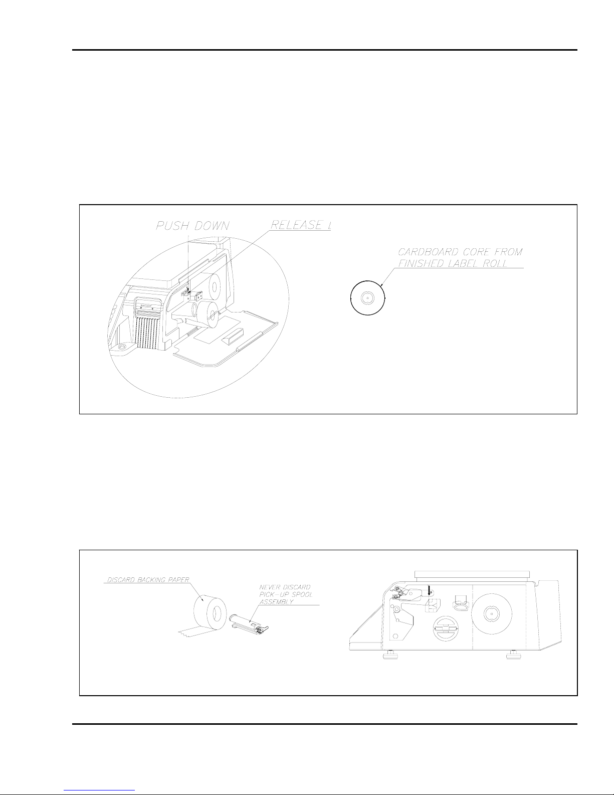
2) Find and remove t he Pick-Up Spool assembly and the label-roll Pin. Also, find the Print Head Release
Lever and push it in the direction indicat ed. The print head will be in the “UP” position. I f there were
any labels previously installed please remove all the collected backing paper from the Pick-Up Spool
assembly. The Pick-Up Spool assembly automatically collapses when it is removed from the Pick-Up
shaft. This makes the removal of the backing paper very simple. Also remove the cardboard paper
roll core if there was a label roll previously installed. (See fig.)
27
5 Quick Set-Up
3) Take the new roll of labels and find the ending. Peel-off and discard about one foot (12 inches) of
labels from the backing before installing the roll into the scale. Place the label in the scale as shown
and thread the backing through the appropriate places. (See fig.)
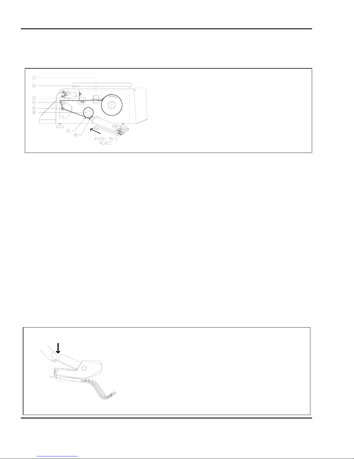
4) Please view the checkpoints on the diagram below as you read these directions to thread the labels.
c Feed the backing paper over the width-adjusting Pressure Shaft lifting the Pressure Plate in order to
place the backing between the two making sure that the width adjustment is as exact as possible
without bending the backing paper.
d Feed the backing paper inside the slot between the Gap sensor assembly making sure that the
labels travel under the Secondary width-adjuster.
Make sure that labels are not pushed all the way to the left on the Peel-Off bar. Leave about ¼ inch
space left of the backing paper
f Feed the backing over the Rubber Roller and under the Print Head being careful not to touch the
underside of the Print Head.
g Continue to feed the backing paper over the Peel-off Bar.
h Continue to feed it under the Return Roller.
i Feed the backing under and around the Pick-Up Shaft.
j Now attach the Pick Up Spool assembly onto the Pick-Up Shaft and turn it slowly counterclockwise in
order to tighten the backing paper.
5) Push the Print Head down in order to lock it back in place. You will feel and hear it lock in place.
Close the printer access panel and press the ON/OFF key. You have completed the label roll
installation. (See fig.)
28
 Loading...