

CAS EB Series, EB-60, EB-150 Service Manual

EB Service Manual
1 2007/06/13
EB SERVICE MANUAL

EB Service Manual
2 2007/06/13
< Table of Contents >
1. Introduction ............................................................................................................................... 4
1.1. Preface .................................................................................................................................... 4
1.2. Precaution.............................................................................................................................4
1.3. Specifications......................................................................................................................5
1.4. Dimension.............................................................................................................................. 6
1.5. Key & SYMBOLS ON DISPLAY.................................................................................... 7
1.6. Sealing Method................................................................................................................... 9
2. Calibration.................................................................................................................................11
2.1. General Calibration........................................................................................................ 11
2.1.1. C4 Setting ........................................................................................................... 12
2.1.1.1. C4-1 Setting................................................................. 12
2.1.1.2. C4-2 Setting................................................................. 12
2.1.1.3. C4-3 Setting................................................................. 12
2.1.1.4. C4-4 Setting................................................................. 13
2.1.1.5. C4-5 Setting................................................................. 13
2.1.2. SPAN Calibration Setting (C-3).............................................................. 14
2.1.3. Gravity Constant Value Setting (C-9) ................................................ 14
2.1.4. Calibration factor Setting (C-10).......................................................... 15
2.1.5. Displaying Real A/D Value (C-5).......................................................... 15
2.1.6. Input Function Key Code (C-6).............................................................. 16
2.1.7. Percent Calibration (C-7).......................................................................... 17
2.1.8. Battery Calibration (C-8)........................................................................... 17
3. The Schematics and Diagram......................................................................................... 18
3.1. System Block Diagram................................................................................................. 18
3.2. Circuit Diagram ................................................................................................................ 19
3.2.1. Main and Power............................................................................................... 19
3.2.2. Display part ....................................................................................................... 20
3.2.3. Key Part ............................................................................................................... 21
4. Exploded View......................................................................................................................... 22
5. Load Cell drawing.................................................................................................................. 23
6. Part Location............................................................................................................................ 24
6.1. Main PCB (Top) ................................................................................................................ 24
6.2. Main PCB (Bottom) ........................................................................................................ 25
6.3. Rear Display PCB (Top)............................................................................................... 26

EB Service Manual
3 2007/06/13
6.4. Rear Display PCB (Bottom) ....................................................................................... 26
6.5. Terminal PCB (Top) ....................................................................................................... 27
6.6. Terminal PCB (Bottom)............................................................................................... 27
6.7. Cal PCB (Top).................................................................................................................... 28
7. Error Messages & Solution............................................................................................... 29
8. Part List....................................................................................................................................... 30

EB Service Manual
4 2007/06/13
1. Introduction
1.1. Preface
Thank you for purchasing of our CAS scale.
This scale has been designed with CAS reliability, under rigid quality control
and with outstanding performance.
WE hope that your departments enjoy with high quality of CAS product.
This manual will help you with proper operations and care of the EB series.
Please keep it handy for the future references.
1.2. Precaution
• Make sure that you plug your scale into the proper power outlet.
• Place the scale on a flat and stable surface.
• Plug into a power outlet 30 minutes before operations.
• Keep the scale away from strong EMI noises may cause incorrect weight readings.
• This scale must be installed in a dry and liquid free environment.
• Do not subject the scale to sudden temperature changes.
• Do not subject the platter to sudden shocks.
• If the scale is not properly level, please adjust the 4 legs at the bottom of the
scale (turn legs clockwise or counterclockwise) so as to center the bubble of the
leveling gauge inside the indicated circle.
EB Service Manual
5 2007/06/13
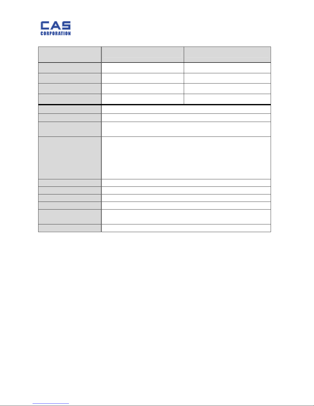
1.3. Specifications
EB -60 EB-150
Capacity / e
60 kg / 0.02 kg 150 kg / 0.5 kg
Internal
1 / 60,000 1 / 60,000
External
1/3,000 (Dual) 1/3,000 (Dual)
Tare
29.99 Kg 59.98 Kg
Display Weight(6), unit price(6), total price(6)
Indicators STABLE, ZERO, NET, Battery
Keys
Number(0~9, 00), Clear, ZERO, TARE, PLU Save, PLU Call,
Battery, BL, X, -(cancel), +(add), SUM(TTP), Mode, Power ON/OFF
Functions
• Direct PLU(24) / Indirect PLU(200)
• Price computing scale
• Low Battery Indication function
• Auto Power Off, Auto BL off
• Beep Sound Off Function
Weight 15kg
Power 6V 5 Ah Pb Battery or 9 V Adaptor
Op.Temperature - 10 °C ~ +40 °C
Options Rear Display, Stainless-tray, Adaptor, RS232
Minimum Voltage
Level The Battery
About 5.7V
Operation time About 200HR
EB Service Manual
6 2007/06/13
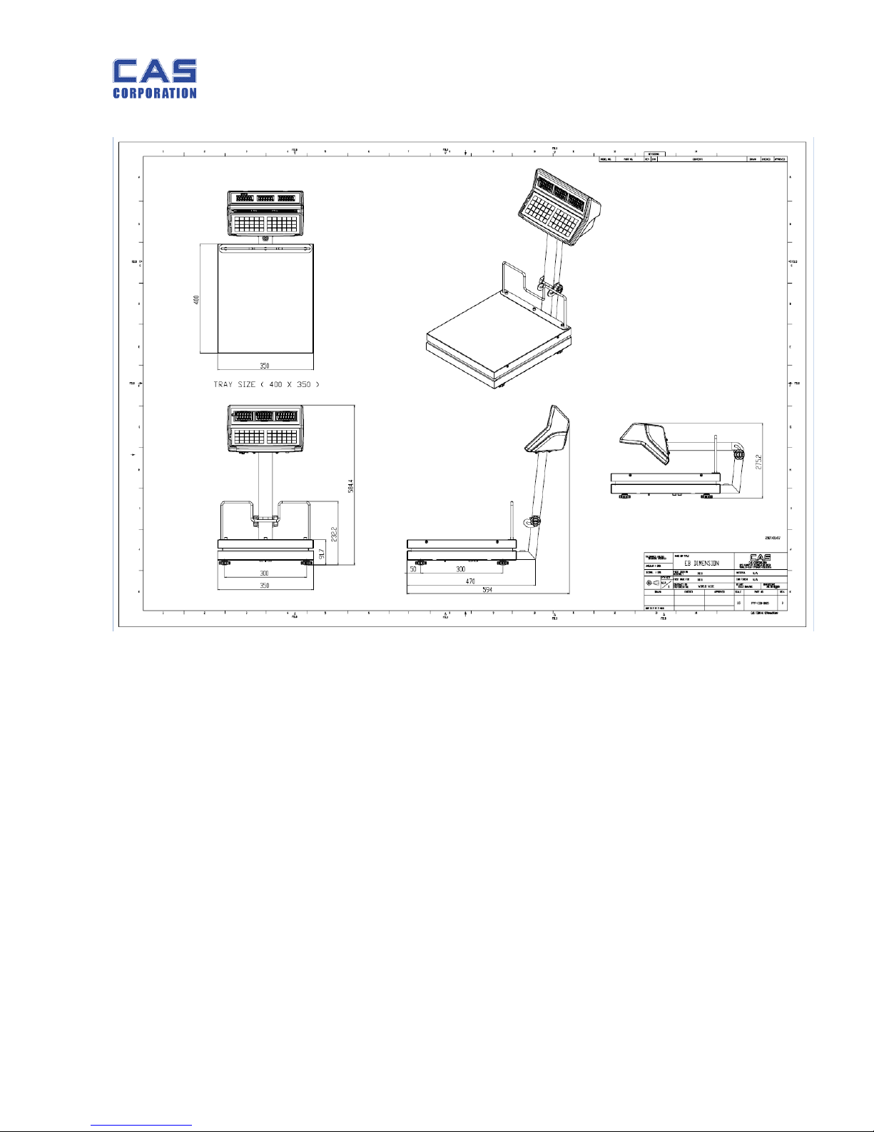
1.4. Dimension
EB Service Manual
7 2007/06/13
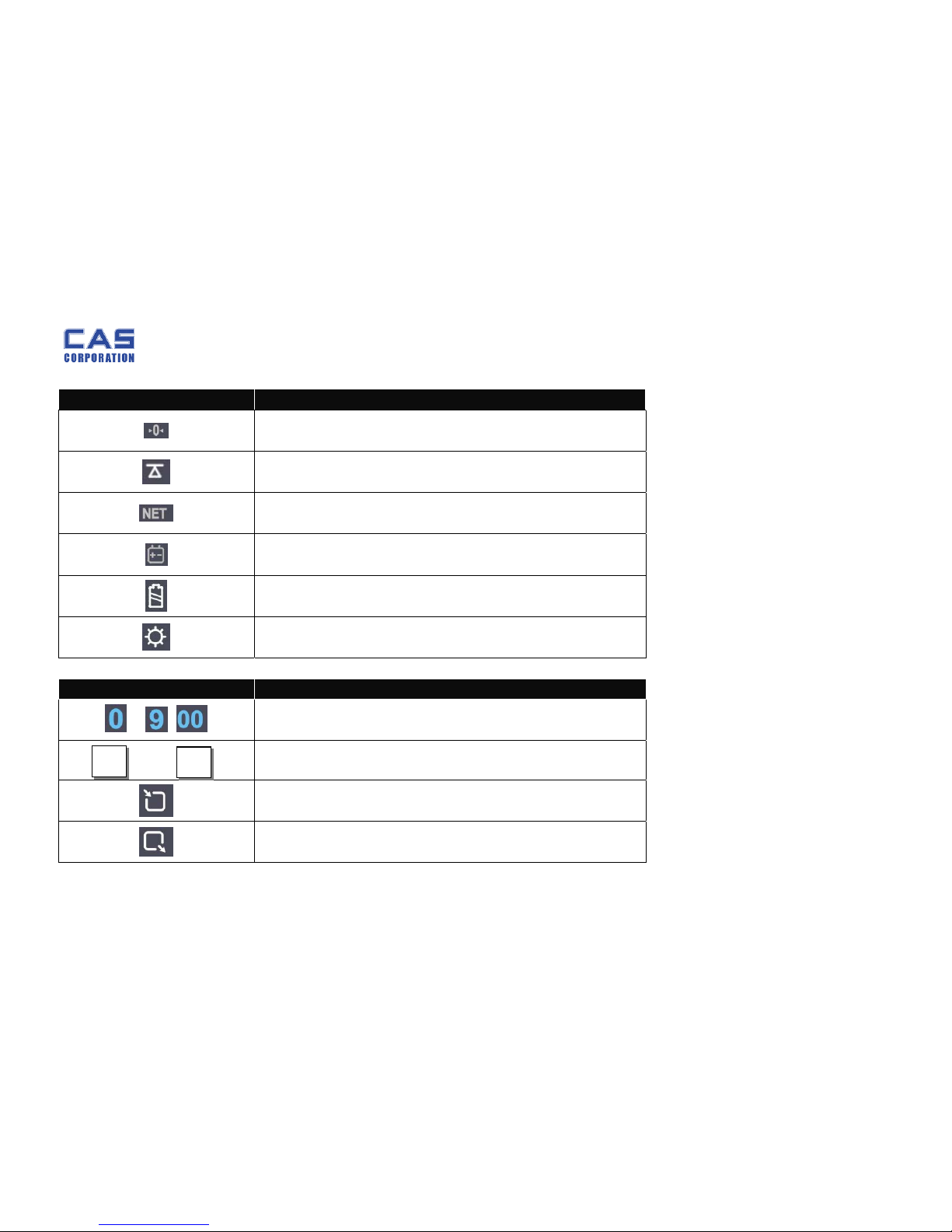
1.5. Key & SYMBOLS ON DISPLAY
SYMBOLS DESCRIPTION
To adjust zero
Stable status
Tare on
Charge status
Display battery status
Back Light On status
KEYS FUNCTIONS
~ ,
To input all of numerical data
~
Direct PLU keys (24EA)
To save PLU
To call up PLU
EB Service Manual
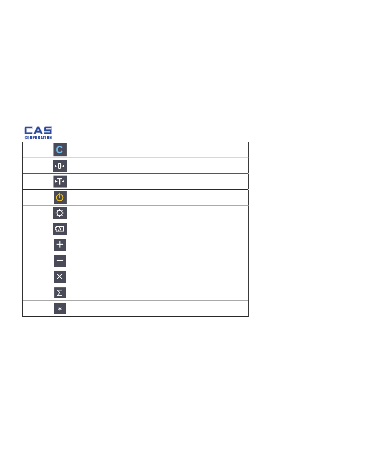
8 2007/06/13
To clear data
To set zero
To set or clear tare value
To turn on & off the scale
To turn on & off the backlight
Display battery voltage(%)
To make several sales transaction by adding up
To make discount transaction
To multiply the same item when making sales transaction
To check total sales amount or finalize sales transaction
To soft key
EB Service Manual
9 2007/06/13
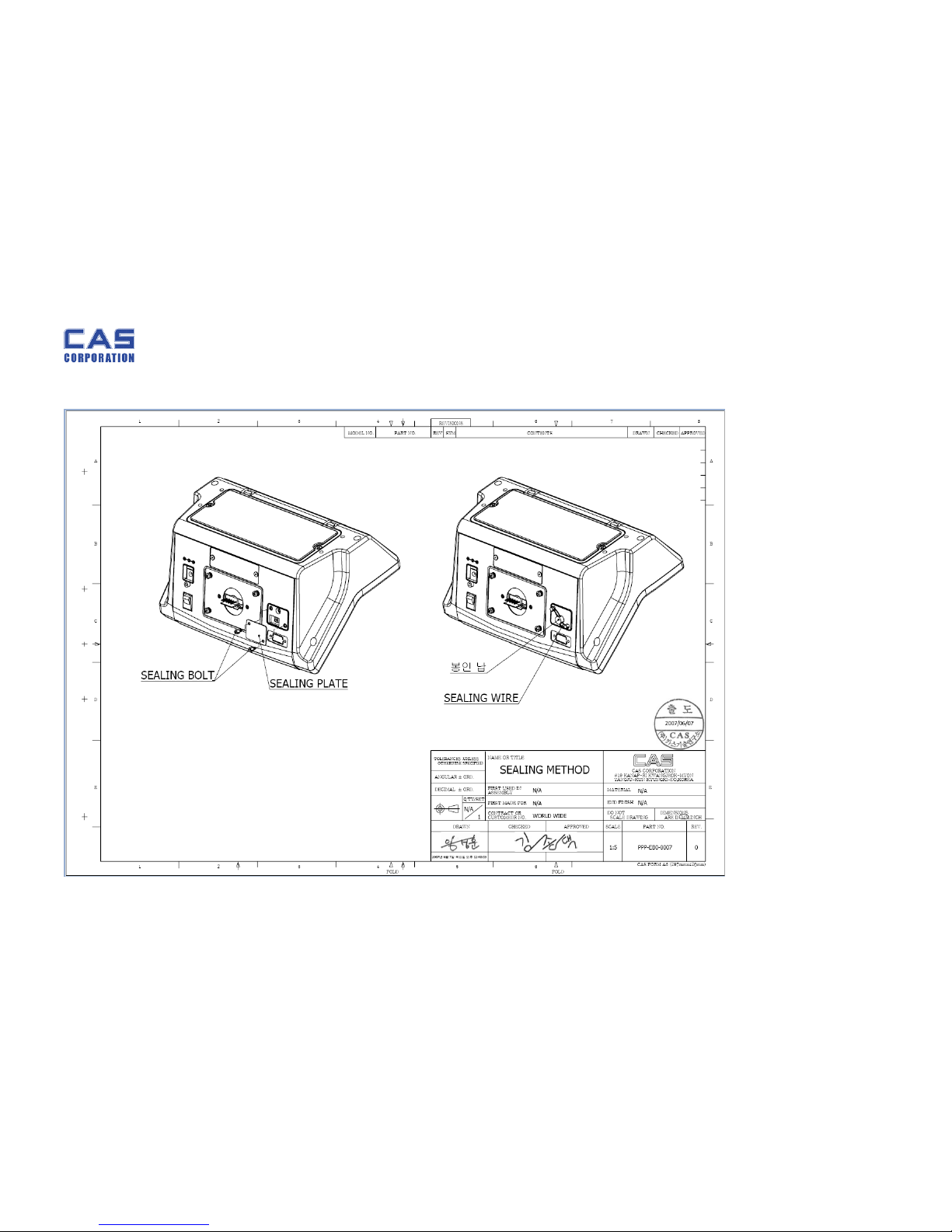
1.6. Sealing Method
[PLATE]
EB Service Manual
10 2007/06/13
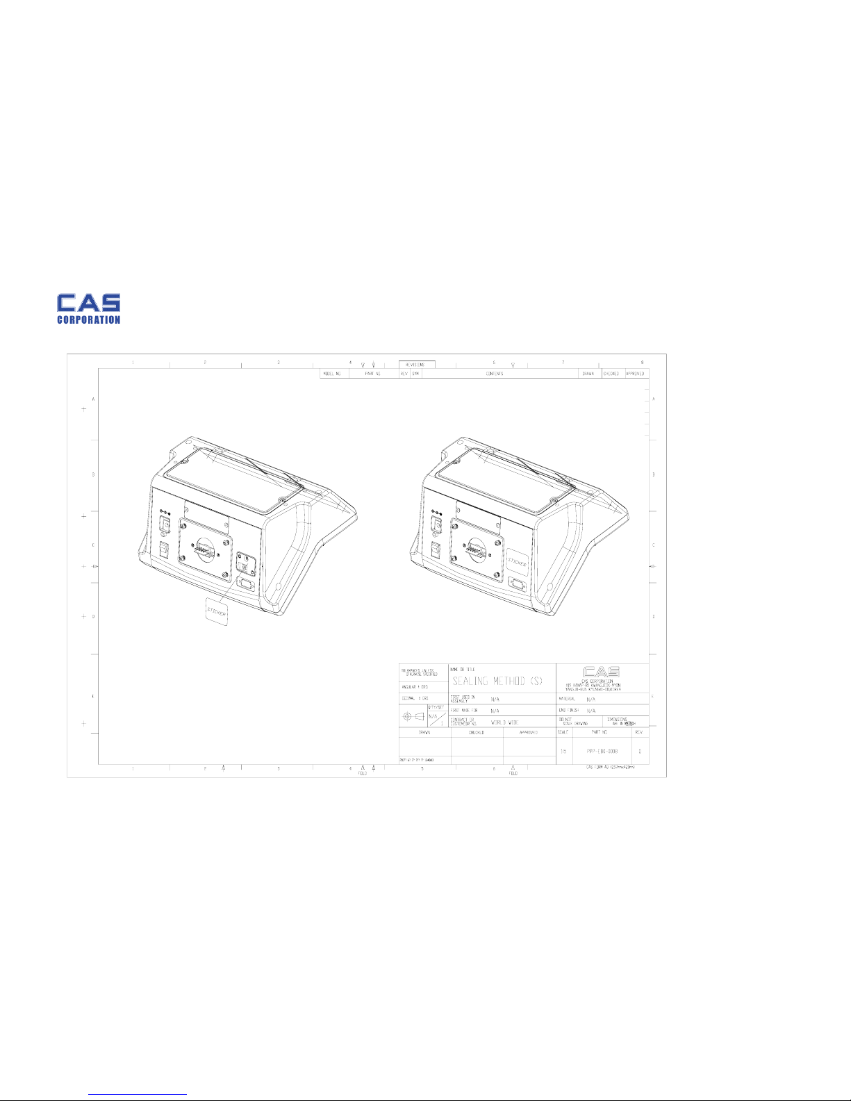
[STICKER]
 Loading...