

CAS DH Owner's Manual
2

3
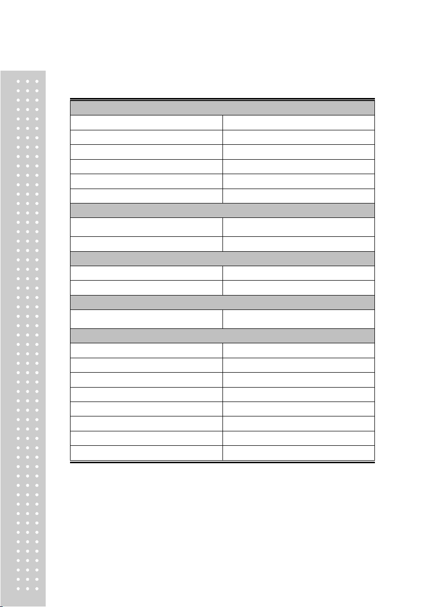
Technical Parameter
CONTENTS
............................................
4
Installation and Connection
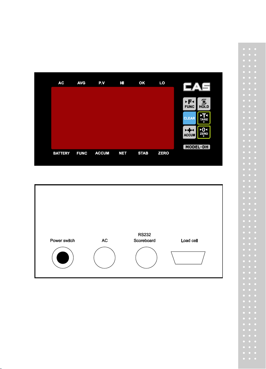
1. Indicator Diagram
2. Loadcell Connection
...............................................
...........................................
.............................
3. Serial Communication interface and Scoreboard
Operation Instruction
1. Serial communication
2. Key Operation
......................................................
3. Weighing Operation
Calibration Description
User Function Setting
Error Indication
Maintenance and attention
...................................................
.........................................
.......................................
............................................
...................................
........................................
............................
* Dear users :
Please read the manual carefully before using this indicator.
....
5
5
6
7
9
9
9
9
11
14
17
17
4
1. Analog part
Class of Accuracy
Class III, n=3000
Input signal range
-19mV ~ 19mV
Conversion speed
10 times/sec
Gain drift
0.03%
Excitation voltage
DC 5V
Loadcell connection
Max. 4ea 350 Ω Loadcell
2. Display part
Display range
-99999 ~ 999999
(decimal point is not considered)
Scale division
1/2/5/10/20/50 optional
3. Serial communication interface
Signal
RS232 signal
Transmission distance
< 20m
4. Score board display interface
Adopts serial output method,
current loop signal, transmission distance
≤ 1000 M
5. Operation environment
Power supply
AC220V; 50, 60Hz (-2% ~ +2%)
Battery life time
Approx. 30 hours
Battery charging time
Approx. 15 hours
Operating temperature
0 ℃ ~ 40 ℃
Storage and transport temperature
- 25 ℃ ~ 55 ℃
Relative humidity
≤ 85%RH
Fuse
500mA
Weight
Approx. 2 kg
Technical Parameter
5
Installation and Connection
1. Indicator Diagram
Front cover
Back cover
6
▲!The connections of Loadcell and indicator must be reliable, and the shielded cable of
Loadcell must be reliably grounded. Connections wires shall not be plugged and pulled when the
indicator is in a Power-up State in order to prevent static electricity damaging to the indicator or
Load cell.
▲!Since both Load cell and indicator are static-sensitive device, anti-static measures must be
practically taken in the use, and welding or other strong-electric operations on weighing platform are
strictly prohibited. In the thunderstorm season, reliable lightning protection measures must be taken to
prevent lightning damaging the senor and instrument and to ensure the operator safety and the safe
operation of weighing equipment and related equipment.
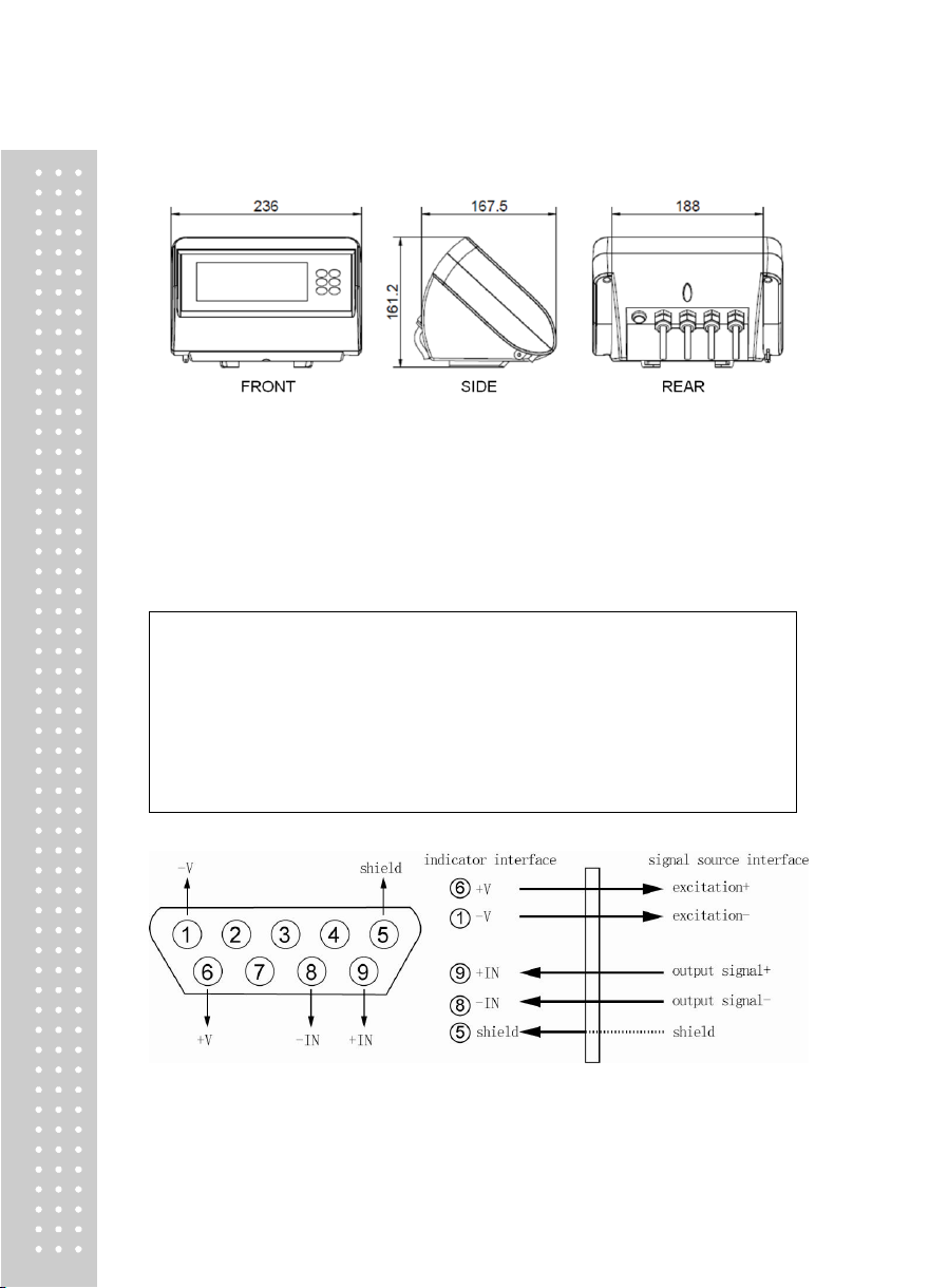
Dimensions
2. Load cell Connection
■ The Load cell is connected through 9-pin plug socket (hole). Figure 2-3 shows the meaning
of each pin.
■ Please use 4-core shielded cable.
7
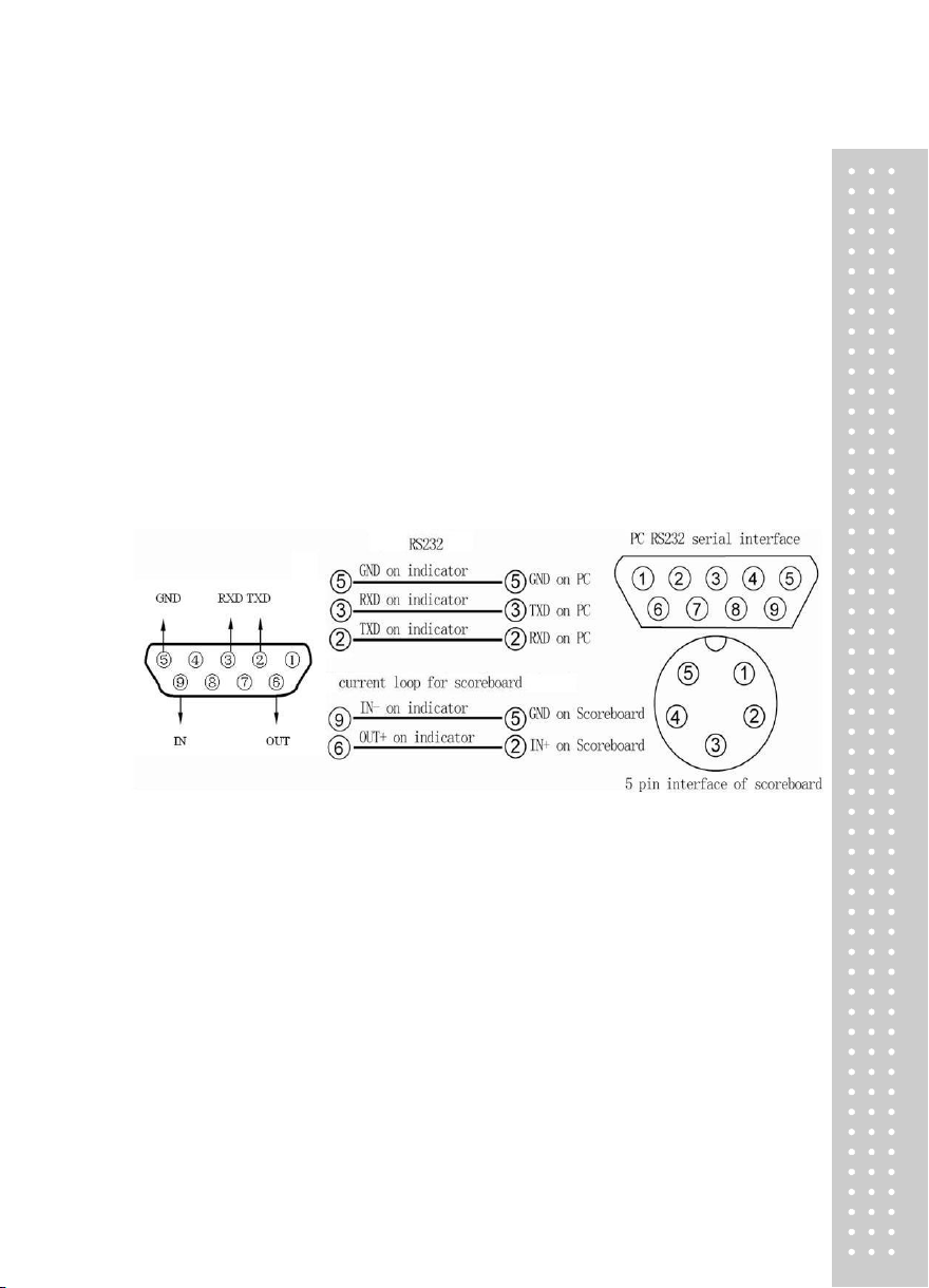
3. Serial Communication interface and Scoreboard
(Note : this function is optional)
Serial communication interface
Communication interface uses 5-pin socket (pin) and all the data is ASCII code, and there are 10 bits
in every data group, and the 1st bit is start bit and the 10th bit is stop bit, and there are 8 bits in the
middle and there is no parity bit.
1. Connection mode
CAS DH communication interface uses 9-pin socket (pin). Lead pin is defined as follows: pin 2 is for
TXD (serial communication data line) and pin 5 is for ground wire; shielded cable is recommended to
be used as connection line. See below Figure details.
Communication for scoreboard and RS232
2. Interface parameter
① Signal : RS232C
② Baud rate : 1200/2400/4800/9600
3. Communication method
Method 1 P5=2 continuous transmission
Transmitted data is weight. (gross weight, net weight or tare weight, decided by parameter P4).
Gross weight format is : ww000.000kg or ww000.000lb
Net weight format is : wn000.000kg or wn000.000lb
Tare weight format is : wt000.000kg or wt000.000lb
Note : Above decimal point position is determined by decimal point position setting of the indicator.
 Loading...