

Page 1
SL24
SL40
SL56
Revision 1
76-00024
SERIES
STUDIO / LIVE
Owners Manual
Page 2
Introduction
Sound Quality and In-Line Flexibility
There are a multitude of considerations that a sound engineer must weigh when choosing the right console. Whether the
console will be used for live sound reinforcement or studio recording, ultimately the choice of a console always focuses on
sound quality and signal routing flexibility. These were primary design considerations for the new S/L series consoles from
Carvin.
Sound
Carvin’s S/L consoles feature the ultimate Analog Devices SSM2017 mic/line preamp (on each
channel). Other major console manufacturers sometimes offer this pre-amp as an
upgrade option. In order to preserve the pristine signal quality of the
S/L’s preamp circuits throughout the signal path, Carvin utilized
surface mount P.C. technology with expensive high quality
surface mount components and high slew rate opamps. The S/L’s ingenious design features extremely
large ground traces, double sided, plated-through
FR4 military spec circuit boards and other design
aspects normally found in only the most expensive world class
consoles. As a result, the S/L series consoles offer some of the finest EIN,
headroom, cross-talk and S/N specs of any console regardless of size or price! The S/L’s 4band EQ section features two semi-parametric mid band and EQ in/out switching, as well as Lo-cut switching. The sweet
sound of this EQ cannot be overstated. Carvin spent a great deal of time and effort to ensure that the delicate subtleties of the
incoming signals are not disturbed by the EQ section, but that the character and flavor of the original signal be enhanced. The
warmth & intensity of the new S/L consoles from Carvin are startling! Respective of any other console you may have been considering (for either live sound or recording), Carvin promises you will not find a better sounding console!
Signal Routing and Capabilities
Like any exceptional recording console, the S/L consoles offer advanced In-Line signal routing. The S/L consoles easily meet
both pre and post production studio requirements, as well as offering additional ruggedness and special routing capabilities
normally reserved for live sound mixing. If you are an experienced sound engineer, we invite you to review the signal routing
and flexibility of this console for either application. Carvin is always eager to answer any questions you may have regarding
the S/L console and how it will solve your specific needs. Even if you are just a novice, be assured the intelligent design and
flexibility of the new S/L series consoles will meet all your sound needs and will allow you to discover aspects of your mixes
you may not have even considered.
The channel format of the S/L consoles offers some unique features and capabilities.
Just a few (for your consideration) are as follows:
1) Phase Switch (per channel): Most mixes neglect the very important aspect of proper phase. When utilizing multiple microphones and signal sources, it is imperative that the final mixed signal be properly “in-phase”. The sound in the room and on
each microphone may be dynamic and lively, but when the final mix is accomplished the sound can become dull and lacking
brilliance. The close proximity of multiple microphones recording the same source can result in a mix that sounds muddy or
boxey. The channel phase switch on each mic channel ensures that your mixes will remain as brilliant and lively as the original
instrument.
2) Channel Tape Switch - This function allows you to quickly configure your console for multi-track mixdown. By pressing the
TAPE switch, your multi-track tape returns signal flow through the normal channel signal path for EQ, effects and basic post
production mixdown.
2
Studio Live Consoles
Page 3

3) Tape Selection for Buses 5 & 6 and 7 & 8 (depending upon the selection of the Input Tape Switch) allows interconnecting
either the tape input signal or the mic input to these buses. Depending upon the configuration of your console, this switch will
allow for individual bus routing for quick overdubbing while simultaneously setting up the stereo control room mix. For most
recording situations, the input tape switch will be routing the mic signal through the channel and then (from the direct output)
to the multi-track tape deck. The output of the multi-track tape deck is then fed back into the tape inputs of the channel and
the tape switches will be depressed for buses 5&6 (for the studio headphone mixes) and for buses 7&8 for tape monitoring
and stereo control room monitoring. In this configuration, punch-ins are a snap and a quick rough tape mix is automatic. The
S/L consoles can accomplish just about any special signal routing requirement you may have. But, there is one aspect of the
tape switch that is not normally considered. On the S/L console, you can use the channel tape input as a line input! You can
then select the tape switch and route the signal to the stereo bus 7&8. From the 7&8 stereo bus output, you can select the L/R
switch to route the signal back to the console’s L/R master faders. This this feature will configure your 24 input console to a
48 input console (more if you have a 40 or 56 channel) with 24 mic pre’s and 24 additional line -ins! Yet another fantastic and
unique feature of the Carvin S/L series consoles!
4) Channel Solo & PFL - The S/L consoles are capable of both solo and PFL (Pre Fader Listen) monitoring. For live applications you may wish to configure your console for PFL (especially while setting up the system). But, you may decide that you
prefer to have the function of the S/L’s “solo-in-place” as you progress with your mix. Solo-in-place means that you can monitor the exact level as it is placed in the stereo field. The ability to quickly configure your console for either type of monitoring is
both unique and yet another advanced feature of the S/L series consoles.
The above features are only a few of the unique options offered by the S/L console yet there are so many advanced capabilities
such as:
Aux send switching to the XLR balanced outputs (for balanced signal sends especially useful for live sound reinforcement)
Stereo Subgroup to L/R interconnects
Control Room to Studio Output selection
Fully isolated power supply utilizing a heavy-duty Speakon™ cable
We simply cannot explain all the configurations and capabilities of these extremely versatile consoles in this short introduction. We encourage you to read the manual and if you have questions call and allow our product experts help direct you to the
advanced features available with the S/L series. Without a doubt Carvin’s new S/L consoles represent a significant advancement in home studio as well as live sound mixing. The fact that they are value priced is just another bonus you receive from
your new Carvin S/L series console.
3
Page 4

RECEIVING INSPECTION—read before getting started
INSPECT YOUR MIXER FOR ANY DAMAGE which may have occurred during shipping. If any damage is found,
please notify the shipping company and CARVIN immediately.
SAVE THE CARTON & ALL PACKING MATERIALS. In the event you have to re-ship your unit, the S/L console
will only be accepted in our factory designed shipping carton or damage could result in which CARVIN and the shipping company are not responsible for.
SAVE YOUR INVOICE. It will be required for warranty service if needed in the future.
SHIPMENT SHORTAGE. If you find items missing, they may have been shipped separately. Please allow several
days for the rest of your order to arrive before inquiring.
RECORD THE SERIAL NUMBER on the enclosed warranty card and on this manual for your records. Keep your
portion of the card and return the portion with your name and comments to us.
For the new owner
Congratulations on your selection of a Carvin product “The Professional's Choice.” Your S/L series console
demonstrates Carvin's commitment to producing the highest quality & most sophisticated engineering in the audio
industry today. Its wide acceptance and use by industry professionals illustrates the basis for Carvin's recognition
as “The Professional's Choice.”
Professionalism can only be measured from the results people achieve through their efforts and knowledge. It is
not something that automatically happens when buying new or more sophisticated equipment. Rather, it's what
you do with the equipment and how well you do it that ultimately makes the point. We are certain your new
CARVlN console will deliver the performance necessary for you to achieve solid results, and ultimately enjoy a high
degree of professionalism.
To compliment your new console and help you acquire that knowledge, we've included this manual. All of the
information you need to be up and running is right here! You'll find using this manual easy and convenient.
We've gone to great lengths to make it so. We've attempted to present the technical aspects of your new console
accurately and in “plain English”. But, if you have any questions that are not answered here, please call us at our
toll free numbers. Our sales staff is well versed in the technical aspects of our products and are waiting to assist
you with any questions you may have. We sincerely wish to ensure your complete satisfaction and enjoyment with
your new console.
If you would like to comment on features or performance of your new console, please feel free to contact us.
Comments from our customers have always helped us improve and further develop our products. We sincerely
welcome any comments or ideas you may have.
Please, send in the warranty card. Although it is not absolutely necessary to ensure warranty protection, it will
allow us to better know how you are using our equipment while keeping a ready reference for our files. Sending in
the warranty card also helps us to mail literature and information that may be of interest to you as a professional
musician. Let us know where you are so we can keep in touch!
In this manual there are diagrams and descriptions to aid you in understanding your new console. So, with this
manual in hand, you hold the key to proper operation and the ability to achieve professional results.
May you enjoy many years of success and fun with your new CARVIN console!
TOLL FREE (800)-854-2235
4
For your records, you may wish to record the following information.
Serial No._____________________ Invoice Date_______________
Page 5
Quick set up - Before power is turned on.
1) Be sure the SLP5600 power supply and AC cord is correct for your region (120 Volt or 230 volt).
2) Use only a grounded (3 prong) power outlet to prevent a shock hazard. This also provides the quietest grounding for your mixer.
3) Zeroing the console knobs and switches insures the current status of your mixer and reduces surprises when initially plugging in instruments and microphones.
Zeroing procedure:
Channel - Turn all EQ gain controls to their center positions.
Turn the mic-pre gain controls to their full counter-clockwise position.
Turn all auxiliary send controls counter-clockwise to “0”.
Place channel faders to the down position.
Place all channel switches to the up position.
Master - Place all master and group faders to the down position.
Turn all control room levels counter clockwise to “0”
Turn all Auxiliary send master levels counter clockwise to “0”.
Turn all stereo return levels counter clockwise to “0”.
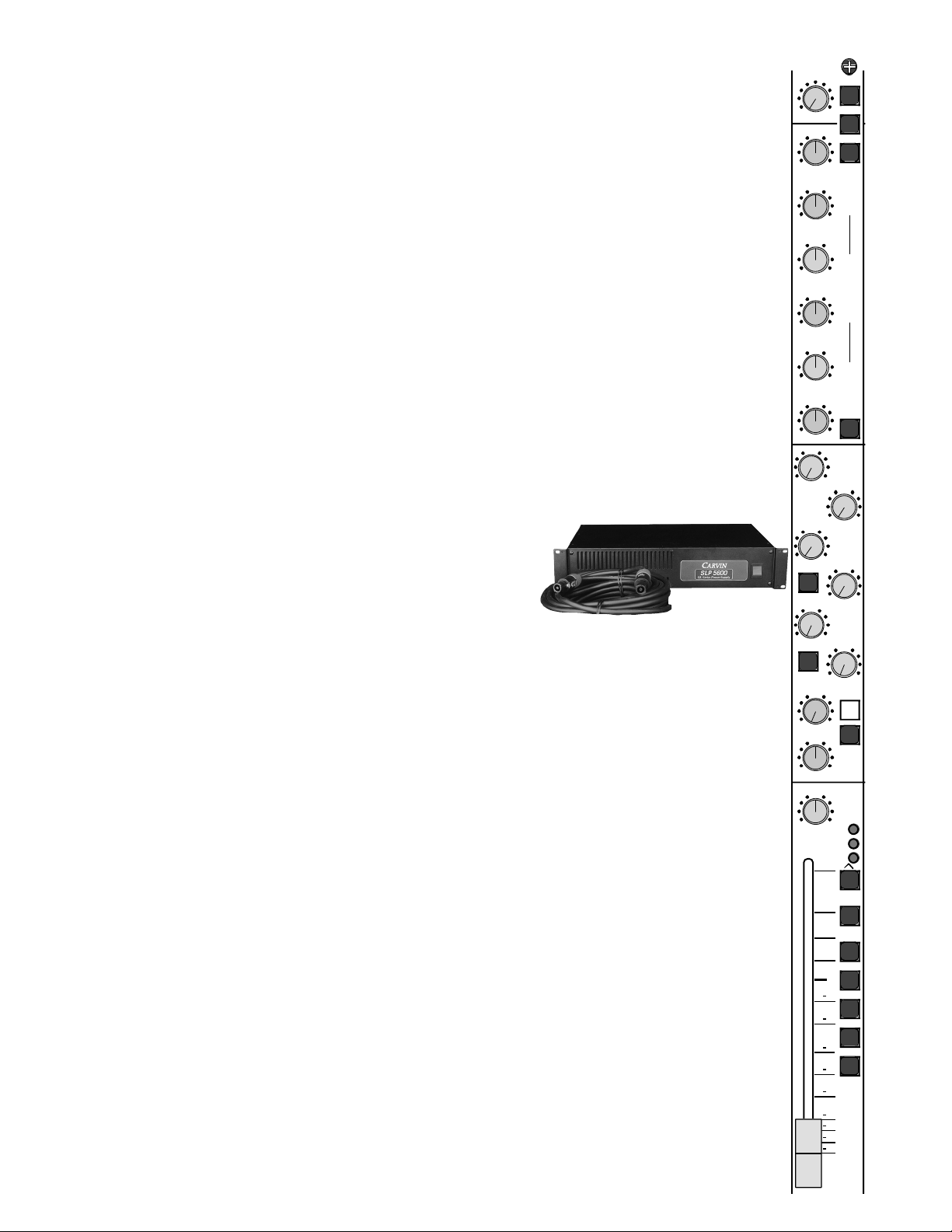
4) The SL mixer series uses an external power supply, the SLP5600.
AC power is connected to the SLP5600 and is in turn connected to
the mixer via a 4 wire Speakon™ cable. If an alternate Speakon™
cable is to be used, be sure it is a 4 wire cable. Not all Speakon™
cables have 4 wires.
5) After connecting your power supply and zeroing the console, turn on the mixer via the red power
switch on the SLP5600 power supply. Test the mixer by plugging a microphone into a channel XLR
input, turn up the gain control at the top of the channel and turn up the channels fader. While talking
into the microphone, the channel meters should be showing signal. Some adjustment to the gain control and fader may be needed to see the signal on the channel meters. Now assign the channel to any
of the master groups or Left-Right via the channel assignment switches 1-2, 3-4, 5-6, 7-8, or L-R.
After adjusting the corresponding master fader, the master meters should be showing signal.
This is a very simple turn on/setup procedure. However, be sure to read the entire manual. Note;
some features or setup connections may help in your situation because most of the S/L console features are not clear cut Studio or Live functions.
5
7/8
GAIN
HIGH
AUX
SOLO
1-2
3-4
5-6
7-8
L-R
PRE
1-2
C
L
R
-
15
0
+
15
1k
2
00 5k
800
2k
FREQ
0
10
5
0
10
5
0
10
5
0
10
5
0
10
5
0
10
5
0
10
5
5
55
-
15
0
+
15
-
15
LOW
0
+
15
HI
MID
500
80 2k
200
1k
-
15
0
+
15
LOW
MID
MUTE
SOLO
LOW
CUT
PK
3
6
5
4
1
2
FREQ
PAN
78
C
PAN
PRE
FAD
w/EQ
E
T
A
P
6-5
E
T
A
P
N
I
Q
E
E
T
A
P
ES
AH
P
P
R
E
43
-
12
+12
+
9
24
+
6
+
3
0
6
18
3
oo
30
40
50
Set your channel controls as shown.
Page 6

TABLE OF CONTENTS
Introduction . . . . . . . . . . . . . . . . . . .pg 2
a) Receiving Inspection
b) For the new owner
c) Before power is turned on
1. Mixer Overview . . . . . . . . . . . . . .pg 7
2. Installation . . . . . . . . . . . . . . . . .pg 7
3. Input Channel Section . . . . . . . . . .pg 8
4. Master Section . . . . . . . . . . . . . .pg 11
Master I/O section
Left, Right, and Groups
Control Masters
Stereo Returns & Tape IN/OUT
Auxiliary Send Masters
5. Standard Studio Mixer Setups . . . .pg 14
6. Standard Live Mixer Setups . . . . .pg 17
7. Using the Inserts . . . . . . . . . . . . .pg 22
Standard Inserting
Insert as Direct Mic-pre Out
8. Meter Bridge . . . . . . . . . . . . . . .pg 23
9. Power Supply . . . . . . . . . . . . . . .pg 24
10. Cable Connections . . . . . . . . . . .pg 25
11. Block Diagram . . . . . . . . . . . . .pg 26
12. General Specifications . . . . . . . .pg 27
Appendixes
B. Schematics . . . . . . . . . . . . .pgs 28-33
C. Console Dimensions . . . . . . . . . .pg 34
D. Glossary of Terms . . . . . . . . .pgs 35-37
6
Page 7

1. Mixer Overview
The S/L series mixing consoles are designed for Studio and Live performances. S/L series consoles allow the user to perform
multi-track recording where the tracks equal the number of channels for the mixer; either 24, 40, or 56. This ability is due to the
Dual In-line channel format used on the S/L series. Dual In-line channels provide a mixing path for the microphones or other
input devices to be recorded, a mixing path for the individual channel outputs to a recording device’s inputs and finally a mixing
path for the output of the recording device. Live performances benefit from the S/L’s AUX sends that can be used for monitor
mixes or effects processing.
The SL consoles are equipped with :
• 24, 40, 56 channel frames.
• Low noise mic-pre amps EIN=128dB min.
• 4 band, dual mid sweep, Channel EQ.
• 8 auxiliary sends: 2 pre, 2 pre/post, 2 post, (stereo) pre/post fader.
• 4 stereo returns w/ Aux 1 & 2 sends, pan and level.
• 8 master groups w/ L-R, assignment and pan, mute and solo.
• Comprehensive master control room section with separate studio controls.
• Specially designed high current headphone outputs.
2. Installations
7
The S/L series console dimensions are in Appendix B for table size and custom installments. A good installation will keep in
mind placement proximity to potential noise sources and positioning the mixer where the sound can be heard clearly from the
audience’s perspective.
The outboard SLP5600 AC power supply is also a consideration when installing a console of this caliber. The AC power for the
mixer and the rest of the sound system needs to first of all, have the capacity to power the system. Be sure power amps and other
high power portions of the system are on large enough and, if possible, separate breakers. It’s possible to lose one or two power
amps in a large system and deal with a 3-6 dB drop in output but if the power amp takes the mixing console with it, you’ve lost
everything. Also, with AC power try to avoid using the same power outlets used by stage lighting. The performance lights typically require large amounts of power and produce heavy AC power spikes when switched on and off. These lights and many banquet room lights can be on solid state dimmer controllers, which produce noisy spikes on their AC power lines. These noises can
only cause headaches for a sound system and nightmares for a recording studios because some of the spikes are emitted and
can’t be taken out by power conditioners.
The placement of the mixing console in live sound situations is often misunderstood. Especially when a promoter or banquet
director sees the console as taking up valuable floor space or as an eye sore at a fancy show. The placement of the mixing console is very important in hearing the performance from the perspective of the listeners. The placement for routing cables is fairly
obvious, avoid large power transformers, air conditioners and lighting rigs! Note: the best sound location in a room will be near
the console because that’s where the mix is created.
Page 8
8
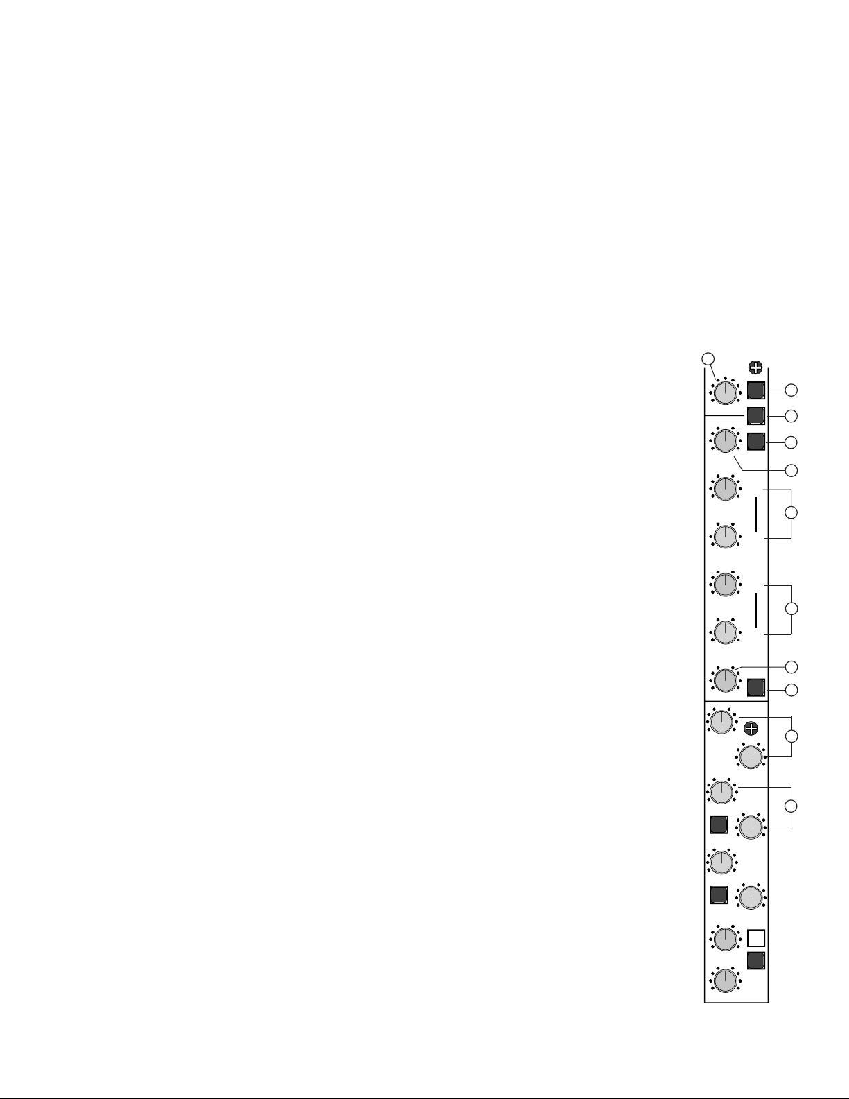
3. Input Channel section
1. 48V PHANTOM POWER SWITCH
This switch provides phantom power for condenser mics in groups of 8 channels. This allows other channel groups to remain
non-powered for instruments and dynamic mics that don’t require phantom power. The 48V switch should not be engaged when
using sources that do not use phantom power.
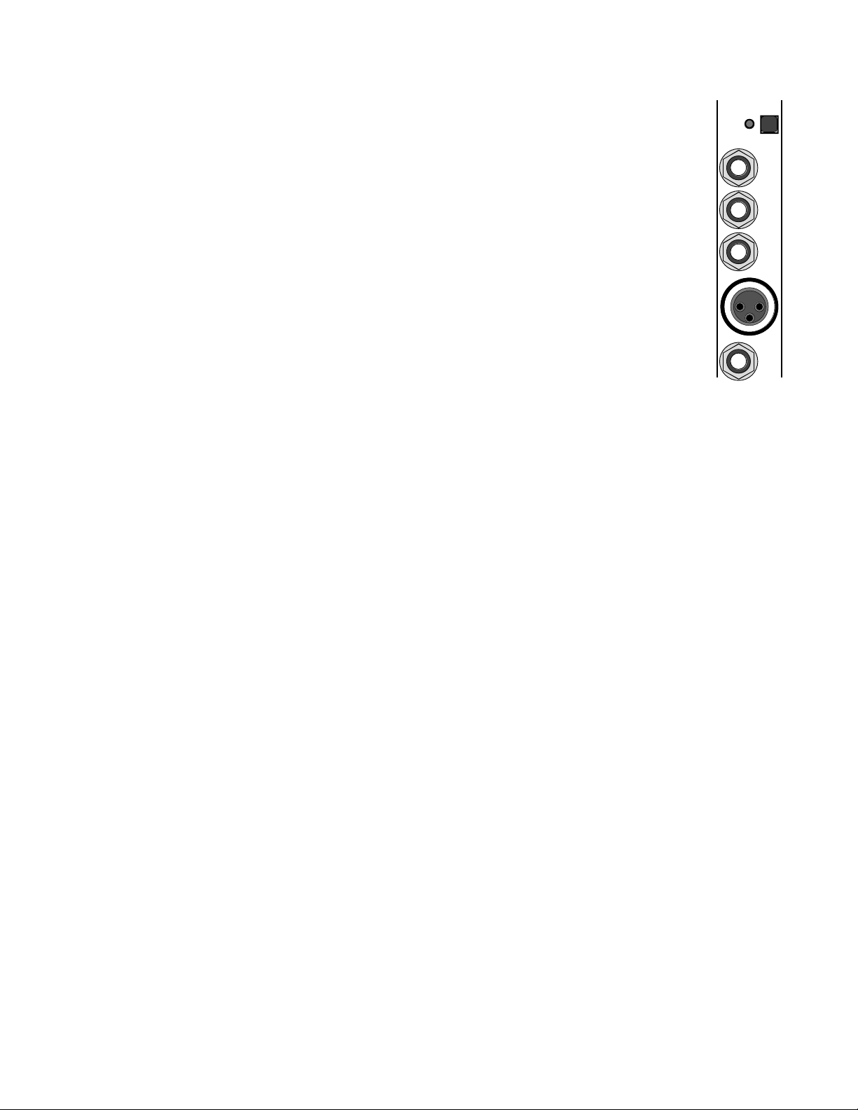
2. CHANNEL DIRECT OUT
The DIRECT OUT is a 1/4” TRS (Tip/Ring/Sleeve) balanced output. The DIRECT OUT provides an output of the channel (post
fader) unaffected by the pan or assignments. This is typically used for multi-track recording where each channel feeds a track
on the recorder. The DIRECT OUT can also be used for sending a channel to an effects unit and to return the effects unit to
another channel for mixing.
3. CHANNEL TAPE IN
The TAPE IN is a 1/4” TRS (Tip/Ring/Sleeve) balanced input. The TAPE IN input jack makes up the alternate input path in the
dual in-line format of the S/L series consoles. This is typically used as a return from a multi-track recorder. The TAPE IN signal
can be accessed via the tape switch, through the Aux 7-8 tape switch or through the Aux 5-6 tape switch.
4. LINE IN
The LINE IN is a 1/4” TRS (Tip/Ring/Sleeve) balanced input. The LINE IN connectors are for connecting balanced and unbalanced instruments, mics and line level sources such as drum machines or keyboards.
5. MIC IN
The MIC IN is an XLR balanced input. These Mic inputs are for connecting professional low impedance microphones. +48V Phantom power is
provided via the grouped phantom power switch for condenser mics requiring phantom power.
6. INSERT
The INSERT is a 1/4” TRS (Tip/Ring/Sleeve) Tip send and a ring return break point. The INSERT jack is typically used for inserting an effects
unit, compressor and/or equalizer at the beginning of the channel’s signal path. In the S/L series, the insert point is located post mic pre-amp
and tape in (depending on the tape switch position) and before the EQ and AUX sends. With an insert cable (1/4” TRS on one end and dual 1/4”
TS “Tip/Sleeve” on the other ends), the TRS end is used at the mixer’s insert jack and the corresponding tip TS (Tip/Sleeve) plug goes to the
units input and the corresponding TS (Tip/Sleeve) plug goes in the units output. To use the INSERT jack as a direct output for an alternate multitrack recording output, use a 1/4” TS (Tip/Sleeve) cable and insert to the first “click” (1/2 insert). Then connect the other end of the cable to an
input on a multi-track recorder. For detailed information on channel insert set up, please see section 7 Using the Insert Jacks on Pg 22
24
PHANTOM
POWER
17-24
TAPE
IN
MIC
LINE
IN
DIRECT
OUT
INSERT
Page 9
3. Input Channel section continued.
9
7. GAIN CONTROL
The GAIN control adjusts the gain of the channels high gain microphone pre-amplifier. This pre-amplifier is designed for professional low
impedance microphones. Monitor the gain level with the PEAK LED. If the LED is constantly lit, decrease the amount of gain. If distortion is
present, decrease your gain until it is eliminated. The GAIN control is also the level control for the LINE IN. Using both MIC IN and LINE IN
inputs at the same time is possible with some deterioration in common mode rejection. To set the gain for optimum signal-to-noise, audition
your audio source and turn the GAIN control up until the PEAK LED starts to flash. The PEAK LED should not be constantly lit but occasional
peaking is OK. Repeat this with each channel. Different mics will require different levels of GAIN.
8. PHASE SWITCH
The PHASE switch reverses the polarity of the input signal to compensate for phase differences due to microphone placement or incorrect wiring
of input cables. This switch should be released (up position) for normal operation.
9. TAPE SWITCH
The TAPE switch provides the Dual In-line channel format. It should be viewed as an input tape switch. In the up position, the MIC and LINE
inputs are feeding the channel’s EQ, sends and fader with assignments. The TAPE IN goes to the TAPE 5-6 and TAPE (AUX 7-8) switches. In
the down position, the routing is “flipped” where the TAPE IN has the EQ, sends and fader with assignments and the mic line inputs are routed
to the TAPE 5-6 and TAPE(AUX 7-8) switches. In a recording situation, the switch up position provides the tracking mode and the down position provides the mix down mode.
10. LOW CUT SWITCH
The LOW CUT switch is a 12dB/Octave high pass filter with a corner frequency of 75Hz. Using the LOW CUT feature helps eliminate unwanted low frequencies. Use the LOW CUT filter to reduce “rumbling” and “boom” noises picked up from mic stands
or hollow body acoustic/electric guitars. This filter can also help tighten bass response by turning up the LOW EQ control while
using the LOW CUT switch.
11. EQ HIGH CONTROL
The High control is an active shelving type of tone control with a corner frequency of 12KHz. The ±15 dB boost and cut provides an overall 30 dB range of powerful EQ control.
12. EQ HI MID LEVEL AND FREQUENCY CONTROLS
The HI MID level and FREQ controls comprise a semi-parametric or sweepable mid equalizer. The level control provides ±15
dB boost and cut with the middle position (center detent) at OdB. The frequency being manipulated is controlled by the frequency control. The FREQ control sets the center frequency for this “bell curve” designed tone control. The HI MID FREQ control ranges from 500Hz to 5KHz. Cutting and boosting frequencies improperly can cause an “un-natural” sound to your vocals
or instruments. Only use these controls to overcome the limitations of the Microphones and room effects to achieve a natural
sound for the entire performance or recording.
13. EQ LOW MID LEVEL AND FREQUENCY CONTROLS
The LOW MID level and FREQ controls comprise a semi-parametric or sweepable mid equalizer. The level control provides ±15
dB boost and cut with the middle position (center detent) at OdB. The frequency being manipulated is controlled by the FREQ
control. The FREQ control sets the center frequency for this for this “bell curve” designed tone control. The LOW MID FREQ
control ranges from 80Hz to 2KHz. Cutting and boosting frequencies improperly can cause an “unnatural” sound to your vocals
or instruments. Only use these controls to overcome the limitations of the microphones and room effects to achieve a natural
sound for the entire performance or recording.
14. EQ LOW
The LOW control is an active shelving type of tone control with a corner frequency of 80Hz. The ±15 dB boost and cut provides
an overall 30 dB range of powerful deep bass EQ control.
15. EQ IN SWITCH
In the down position, the EQ IN SWITCH routes the audio through the channel’s EQ (High, both Mid’s, and the low controls). In
the up position, the EQ IN SWITCH bypasses the EQ section but leaves the LOW CUT switch active in the circuit. The EQ IN
SWITCH is great for comparing the “flat” to EQ sounds.
16. CHANNEL AUX 1 & AUX 2 PRE SENDS
The AUX 1 & AUX 2 controls are pre EQ, pre mute and pre fader sends. These controls are designed as uninterrupted monitoring feeds for stage monitor or in studio tracking. The AUX 1- AUX 2 PRE signal is post INSERT in order to get the benefits
of an inserted channel effect such as a compressor.
17. AUX 3 - 4 PRE SWITCH
The Aux 3 - 4 PRE switch in the up position places AUX 3 and AUX 4 send controls post EQ and post fader (working the same as AUX 5 and
AUX 6). In the down position AUX 3 and AUX 4 send controls, are pre EQ, pre mute and pre fader (working the same as AUX 1 and AUX 2).
7/8
GAIN
HIGH
AUX
PRE
1-2
-
15
0
+
15
1k
2
00 5k
800
2k
FREQ
0
10
5
0
10
5
0
10
5
0
10
5
0
10
5
0
10
5
0
10
5
5
55
-
15
0
+
15
-
15
LOW
0
+
15
HI
MID
500
80 2k
200
1k
-
15
0
+
15
LOW
MID
LOW
CUT
3
6
5
4
1
2
FREQ
78
C
PAN
PRE
FAD
w/EQ
E
T
A
P
6-5
E
T
A
P
N
I
Q
E
E
T
A
P
ES
AH
P
P
R
E
43
-
7
8
9
10
15
11
14
12
13
16
17
Page 10

10
18. CHANNEL AUX 3 AND AUX 4 PRE OR POST SENDS
The AUX 3 and AUX 4 level controls (with the Aux 3 - 4 PRE switch in) provides a total of 4 PRE monitor controls when used with AUX 1 and
AUX 2 (4 monitor mixes). With the Aux 3 - 4 PRE switch out, AUX 3 and AUX 4 can be used with AUX 5 and AUX 6 as effects sends for a total
of 4 post sends.
19. TAPE 5 - 6 SWITCH
The TAPE 5 - 6 switch is linked to the TAPE switch at the top of the channel. Here the alternate input (the input not going to the fader) can be
sourced to AUX 5 and AUX 6. This is used primarily in recording during tracking to provide playback to the studio musicians.
20. CHANNEL AUX 5 AND AUX 6 POST SENDS
The AUX 5 and AUX 6 sends are post EQ and post Fader sends when the TAPE 5-6 switch is up. The AUX 5 and AUX 6 sends are designed for
effects sends or any other fader tracking sends needed. See Tape 5-6 switch for it’s tape input effects on AUX 5 and AUX 6.
21. CHANNEL AUX 7/8 TAPE SWITCH
The 7/8 TAPE switch is linked to the TAPE switch at the top of the channel. Here the alternate input (the input not going to the fader) can be
sourced to the stereo pair of AUX 7 and AUX 8. This is used primarily in recording during tracking to provide playback mixing for the control
room and to the studio musicians.
22. CHANNEL AUX 7/8 PRE FAD W/ EQ SWITCH
The PRE FAD w/ EQ switch in the up position places the stereo pair of AUX 7 and AUX 8 controls post EQ and post fader for use as effects sends.
In the down position, the stereo pair of AUX 7 and AUX 8 controls are post EQ, pre mute and pre fader for stereo in-ear monitor sends or a stereo
drum monitor send. This switch only works when the AUX 7/8 TAPE switch is in the up position.
23. CHANNEL AUX 7-8 PRE OR POST STEREO SENDS
The stereo pair of AUX 7 and AUX 8 level controls are post EQ and post fader sends when the TAPE and PRE FAD w/ EQ switches
are up. The stereo pair is made up of the 7/8 level control and the 7/8 pan control which pans between the two send AUX 7
and AUX 8. The stereo pair of AUX 7 and AUX 8 sends are designed for effects sends or any other fader tracking send needed.
See TAPE switch for its tape input effects on AUX 7 and AUX 8.
24. PAN
This is the channel’s main PAN control. It allows the channel’s signal to be place anywhere in the stereo field from left to right
with the center detent being centered. The PAN control in the studio is typically used for adjusting the stereo field for each
channel, but it is also used for assigning channels to individual buses. The later is typical for live mixing where certain channels are grouped to a single bus for sub group mixing. See Standard Live mixer set-ups for more details on sub mixing.
25. PEAK, SOLO, AND MUTE INDICATORS
The RED PEAK LED indicator is pre-fader and post EQ. A constantly lit LED indicates the signal probably needs a reduction
in the GAIN control to prevent input overloading. The GREEN SOLO LED indicates the solo switch has been pressed on the
channel. The RED MUTE LED indicates the MUTE switch has been pressed on the channel.
26. MUTE SWITCH
The MUTE switch turns off the channel at the fader. Sends 1-2, 3-4 (in pre mode) will be attenuated. This is extremely useful
when you need to mute channels but can’t afford to lose fader settings.
27. SOLO SWITCH
The SOLO switch allows the operator to monitor each channel. The SOLO switch can be set for either “PFL mode” (Pre Fader
Listen) or “SOLO after fader” where the channel’s pan position is heard when soloed. The switch to change the SOLO mode
is found in the CONTROL MASTERS section of the console. See Master Section for more information.
28. ASSIGNMENT SWITCHES
These switches assign the channels’ signal to the group faders (8 buses) for sub-mixing and to the Left & Right faders in the
Master Section. Each channel can be assigned to the 1-2, 3-4, 5-6, 7-8, and L-R Faders in stereo pairs. This feature allows
the operator to group certain channels (such as the channels used to mic an entire drum kit) and assign them to one pair of
the master faders in the 1-2, 3-4 sub group. This sub-mixing feature decreases the number of channel faders that need to be
adjusted. See Standard Live mixer setups for more details on sub mixing.
29. CHANNEL FADER
The channel FADER control is the final level control of the channel before the PAN control. The Fader has a 0dB marker for
nominal setting of the channel. For typical mixing the 0dB position provides the lowest noise and highest headroom for the
channel. The Fader has an added 12dB of gain for signals that need an extra boost in the mix, however pushing the fader
above the 0db marker should be done in moderation. The channels have plenty of headroom but the proper adjustment should
be made at the channel’s input or GAIN control. Be aware of the signals and fader settings so you don’t over-drive the bus or
degrading the channel’s signal by over-driving the faders. The meter bridge and direct outputs are sourced after the fader.
7/8
AUX
SOLO
1-2
3-4
5-6
7-8
L-R
PRE
1-2
C
L
R
0
10
5
0
10
5
0
10
5
0
10
5
0
10
5
0
10
5
0
10
5
MUTE
SOLO
PK
3
6
5
4
1
2
PAN
78
C
PAN
PRE
FAD
w/EQ
E
T
A
P 6
-
5
ETAP
P
R
E 43
-
12
+12
+
9
24
+
6
+
3
0
6
18
3
oo
30
40
50
18
19
21
22
26
27
29
24
20
28
25
23
Page 11
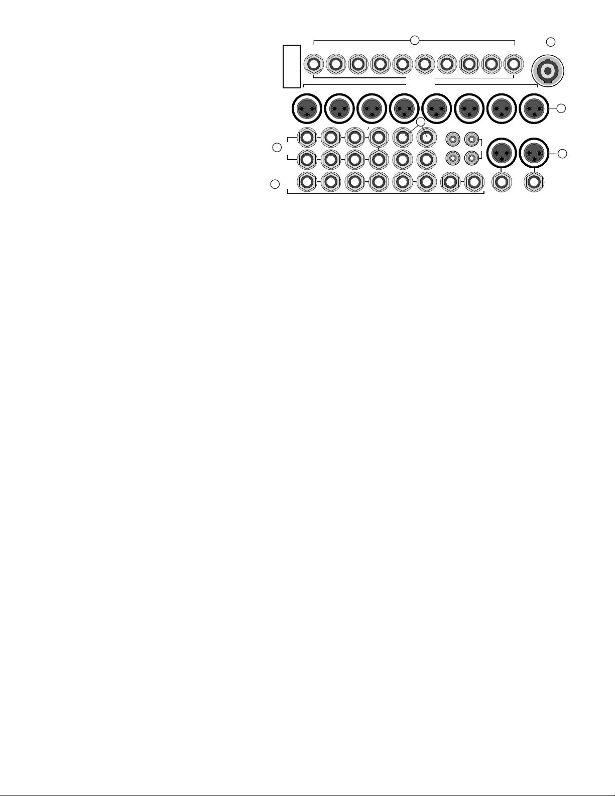
Master I/O Section
Note: All XLR connectors follow the Standard of:
1- Ground 2- Non-inverting (hot) 3- Inverting (cold)
All master 1/4” jacks are unbalanced TS (Tip/Sleeve) with
the exception of the control room and Studio Right jacks used
for PHONES.
1. POWER CONNECTOR
The Speakon™ power connector is used to bring the DC
power into the console from the 2 rack space SLP5600 power
supply. A standard 4 wire Speakon™ cable is required.
2. INSERTS LEFT-RIGHT, GROUPS 1-8
The Master Inserts are 1/4” TRS pre fader inserts. The TRS is the same as the channel inserts with Tip Send-Ring Return. These inserts are
perfect when only a limited number of compressors are available. The Inserts are especially good for unbalanced graphic EQ’s and other unbalanced gear desired on the outputs because it will not effect the XLR balanced outputs.
3. GROUP 1-8 XLR outputs
The Group 1-8 XLR outputs are electronically balanced connectors for the 1-8 Groups. The Group 1-4 XLR’s are also used by AUX 1-4 via the
AUX 1-4 FLIP switches.
4. LEFT and RIGHT XLR and 1/4” CONNECTORS
These XLR connectors are balanced outputs of the Right and Left master outputs. The 1/4” connectors are unbalanced outputs of the same
L-R signals.
5. TAPE IN and OUT RCA’s
Stereo RCA jacks are provided for connecting a tape recorder or CD player. The levels of these jacks are controlled by the corresponding TAPE
IN and TAPE OUT controls in the master section.
6. AUX SEND 1/4” OUTPUTS
Eight 1/4” unbalanced output connectors correspond to the AUX SENDS controls in the master section. Aux 1-4 outputs are also used by the
Group 1-4 masters via the AUX 1-4 Flip switches.
7. STEREO AUX RETURNS 1/4” inputs
Four 1/4” unbalanced stereo pairs (8 inputs) correspond to the 4 STEREO Return controls in the master section. If only one side (right or
left) is used, the jacks are wired so the signal will be supplied to both the right and left path of the stereo return. This allows all the stereo features to work properly with a mono return.
8. CONTROL ROOM 1/4” OUTPUTS (CONTROL L-R, PHONES)
The 1/4” unbalance control room outputs provide individual left and right out for the control room section of the console. The right side is
also configured as a TRS L/R stereo connection for headphones, when nothing is plugged into the left side. The PHONE connection is ideally
suited for live situations. The individual outputs provide an ideal studio monitoring system connection. Both outputs are designed with discrete high current output circuitry for driving headphones and performance studio amplifiers.
9. STUDIO 1/4” OUTPUTS (STUDIO L-R, PHONES)
The 1/4” unbalance STUDIO outputs provide individual left and right out for the STUDIO section of the master. The right side is also configured as a TRS L/R stereo connection for headphones when nothing is plugged into the left side. The PHONE connection is ideally suited for
live situations. The individual outputs provide an ideal studio monitoring system connection. Both outputs are designed with discrete high
current output circuitry for driving headphones and performance studio amplifiers.
Left, Right and Groups
10. POWER LED Verifies power is being supplied to the mixer and the mixer is on.
11. LEFT and RIGHT FADERS
The LEFT and RIGHT FADERS get their signal only from the channel L-R assignment switches, Stereo Returns and the Group 1-8 L-R assignment switches. These faders are post L-R master INSERTS and provide the level adjustments for the left and right XLR and 1/4” outputs.
12. GROUP FADERS
Each GROUP FADER gets its signal from the corresponding channel group assignment switch. These faders are post Group master INSERTS,
and provide the level adjustments for the corresponding Group XLR output.
4. Master Section
1
LEFT
AUX
SEND
5
L
R
IN
OUT
678
1234
AUX
RETURN
POWER
GROUPS
2345678
LR
12LR3
LR
4
LR
INSERTS
1 2345678
L
R
RIGHT
CONTROL
L-R
STUDIO
L-R
PHONES
PHONES
TAPE
11
1
3
4
6
6
7
2
Page 12

12
Control Masters
13. GROUP MUTE’S
The Group MUTE switch mutes the Group signal pre Fader and post insert.
This means the group output and L-R assignment are muted, but not the
send on the insert. The corresponding RED Mute LED indicates the Group
has been muted.
14. GROUP SOLO
The GROUP SOLO is an in place SOLO located after of the group PAN circuit.
15. GROUP L-R AND PAN
The Group L-R Assignment switch is located after the PAN circuit allowing
the group output to be assigned to either the left, the right, or any PAN setting of both masters.
16. GROUP PEAK LED’S
The Group PEAK LED indicates the group is within 3db of clipping. The PEAK
LED is located pre fader post insert in order to indicate the peaking level of
the summing bus or insert return when the group insert is used.
17. SOLO LEVEL
The SOLO level controls the volume of the SOLO bus heard through the control room (and channel PFL when used). The SOLO level also affects
the measured level seen on the L-R meters when something is soloed. This is why the SOLO is center detented to provide a unity gain location
for the solo circuit in order to indicate the desired soloed material correctly on the meters. For normal solos the meters indicate stereo in place
material, when using the channel PFL mode the meters indicate in mono the pre fader material on both meters.
18. SOLO LED
The SOLO led lights up when one or more solo switches have been pressed. The SOLO LED also indicates the control room and master L-R
meters are monitoring the pressed SOLO switches.
19. CHANNEL LISTEN MODE & PFL MODE INDICATOR
The channel listen mode switch provides the option of changing the channel SOLO switches from normally post PAN, stereo in-place solo switches
to pre fader PFL switches used in live applications. The PFL MODE led indicates the channels are in PFL mode.
20. CONTROL ROOM LEVEL
The CONTROL ROOM level adjusts the level of CONTROL ROOM outputs. This
is the master level when using the control room output for studio monitors
or when using the control room right output for PHONES.
21. CONTROL ROOM SELECTION SWITCHES
Use these switches to select what is heard through the control room outputs. When selected these switches
will be heard at the outputs. The switches perform as follows:
AUX 7-8: listens to the final output of the AUX 7-8 masters.
TAPE IN: listens to the post TAPE IN level input.
AUX 1-2: listens to the final output of the AUX 1-2 masters.
MONO: creates a control room left/right summed mono output on the control room outputs.
L-R: listens to the final output LEFT and RIGHT masters.
TO STUDIO: Inputs the control room output to the Studio output.
22. STUDIO LEVEL
The STUDIO level adjusts the level of STUDIO outputs. This is the master level when using the STUDIO outputs for a studio playback system or
when using the STUDIO right output for PHONES.
23. STUDIO SELECTION SWITCHES
Use these switches to select what is heard through the STUDIO outputs. When selected these switches will add together at the outputs.
The switches perform as follows: (Also see TO STUDIO above under the control room selection switches.)
AUX 7-8: listens to the final output of the AUX 7-8 masters.
AUX 1-2: listens to the final output of the AUX 1-2 masters.
L-R: listens to the final output LEFT and RIGHT masters.
PAN PAN PA N PAN PAN PAN PAN PAN
L-R L-R L-R L-R L-R L-R L-R L-R
MUTE MUTE MUTE MUTE MUTE MUTE MUTE MUTE
SOLO SOLO SOLO SOLO SOLO SOLO SOLO SOLO
12345678
L
R
C
L
R
C
L
R
C
L
R
C
L
R
C
L
R
C
L
R
C
L
R
C
L
R
PK PKPK PK PK PK PK PK
R
12345678
L
POWER
oo
0
12
6
+12
+
6
24
30
40
50
oo
0
12
6
+12
+
6
24
30
40
50
oo
0
12
6
+12
+
6
24
30
40
50
oo
0
12
6
+12
+
6
24
30
40
50
oo
0
12
6
+12
+
6
24
30
40
50
oo
0
12
6
+12
+
6
24
30
40
50
oo
0
12
6
+12
+
6
24
30
40
50
oo
12
+12
+
9
30
40
60
+
6
+
3
0
6
20
50
3
oo
12
+12
+
9
30
40
+
6
+
3
0
6
20
50
3
12
+12
+
9
24
+
6
+
3
0
6
18
3
oo
30
40
50
CONTROL MASTERS
STUDIO
AUX 1-2
AUX 7-8
L-R
CHANNEL
LISTEN
MODE
TAPE IN
MONOAUX 1-2
AUX 7-8
L-R
SOLO
PFL MODE
CONTROL
ROOM
SOLO
0
10
5
0
10
5
+6
0
oo
TO
STUDIO
10
15
16
17
18
20
22
21
23
19
14
13
Note:
You can use both the
Control Room outputs and
the Studio outputs for
headphone monitoring.
Page 13

13
Auxiliary Send Masters
24. AUX SENDS 1-6 CONTROLS & PFL
These are the Master levels for Auxiliary Sends. Each has its own PFL switch
to monitor the AUX send buses pre fader.
25. AUX 1-4 FLIP SWITCHES
The AUXiliary FLIP switches on AUX send 1-4 are for the purpose of providing
XLR balanced outputs for these auxiliaries. This is especially useful for balanced
monitor sends. When the switch is down, the output of the auxiliary is sent to
the corresponding group XLR output and meter bridge feed. At the same time, the affected group output is fed to the auxiliaries 1/4” output jack.
No other operation is affected.
26. AUX SENDS 7/8 CONTROL & L-R SWITCH
The AUX SENDS 7/8 CONTROL is a stereo master level for both the AUX Send 7 and 8. The output of AUX 7-8 level can be sent to the L-R masters via the L-R switch providing a route for secondary channel inputs to get to the main L-R mix.
Stereo Returns & Tape IN/OUT
27. STEREO RETURN LEVEL AND PAN
The stereo return level is the main level control for the return. The stereo return PAN works as a balance control for Stereo inputs and as a PAN
control for mono inputs.
28. STEREO RETURN AUX 1 AND AUX 2 SENDS
The Stereo return AUX 1 and AUX 2 send controls allow the returns to be fed to the monitor mixes. These Aux sends are created from summing
the left and right pre-level return signals. Because they are pre-level, they can be controlled independently of the signal going to the main left
right mix.
29. STEREO RETURN MUTE AND SOLO
Each stereo return contains a MUTE and a SOLO switch. The MUTE is equivalent to a L-R assignment on the channels, except it works in the
reverse action. The MUTE switch is post the PAN and LEVEL controls. The SOLO switch is an in-place stereo solo, placed in the same location
as the MUTE (post PAN and LEVEL).
30. TAPE OUT LEVEL AND SOURCE SWITCH.
The TAPE OUT level provides an on board control for the RCA tape output. The level is limited to adding a maximum of +6db to the original
signal going out in order to prevent overdriving the recording equipment used. The L-R or AUX 7-8 source switch is provided to allow the recording of a live performance from the main L-R house mix or an independent mix through the AUX 7-8 sends.
31. TAPE IN LEVEL
This adjusts the level of the signal coming from RCA TAPE IN jacks.
32. TAPE IN L-R AND AUX 1-2 SWITCHES
These switches allow playback of the RCA TAPE IN signal through the main L-R mix and/or the AUX 1-2 monitor mixes.
STEREO RETURNS
4
TAPE
OUT
MUTE
AUX
1-2
TAPE
IN
L-R
AUX 7-8
SOLO
L-R
3
MUTE
SOLO
2
MUTE
SOLO
1
MUTE
PAN
AUX 2
SOLO
AUX 1
0
10
5
0
10
5
0
10
5
0
10
5
0
10
5
0
10
5
0
10
5
0
10
5
0
10
5
0
10
5
0
10
5
0
10
5
C
L
R
C
L
R
C
L
R
C
L
R
PAN
AUX 2
AUX 1
PAN
AUX 2
AUX 1
PAN
AUX 2
AUX 1
+6
0
oo
+6
0
oo
AUX SENDS
6
54321
7/8
L-R
PFL
0
10
5
0
10
5
0
10
5
0
10
5
0
10
5
0
10
5
0
10
5
PFL PFL PFL PFL PFL
FLIP FLIP FLIP FLIP
TO GRP 1
XLR
TO GRP 2
XLR
TO GRP 3
XLR
TO GRP 4
XLR
24
30
27
25
26
31
32
28
Page 14

The following section describes two of the more
common Studio recording setups. These setups
are not the only setups you can use, many of the
connections described here can be combined and
customized to provide the best setup for you.
The first Setup is based on the In-Line recording
method and the second setup is based on the Split
recording method.
In-Line Recording Setup.
The S/L series consoles are designed for In-line
recording. In-line recording is where each mixer channel can handle a mic input, a direct output to a multi-track and a tape return input from
the multi-track. This is due to the dual in-line channel format of the S/L series console. The dual In-line channel is made up of two individual
channel signal paths, a minor path for monitoring and a main, full featured path for tracking and final mix down. These two signal paths are
sourced by two inputs at the MIC input (including LINE IN) and the TAPE IN. With the use of the TAPE switch, either of the two input paths can
flow through either of the two signal paths.
When the TAPE switch is OUT, the MIC/LINE IN goes through the main signal path providing access to: the channel insert, the EQ section, all
the Auxiliaries, the Fader, the DIRECT OUTPUT and Bus assignments. The tape input goes through the minor path, which can be
accessed via the Aux 7-8 “TAPE” switch or the Aux 5-6 “TAPE 5-6” switch. This is the typical setup for tracking (recording instruments to the multi-track unit’s
individual tracks), where a mic is
plugged into the channel’s XLR
MIC input. Then via the channel DIRECT
OUTPUT, the mic is recorded on one track of the
recording unit. At the same time on the channel, the output of the recording unit can be monitored via the tape input and the Aux 7-8 TAPE
switch.
When the TAPE switch is IN the inputs are flipped
and the tape input goes through the main path
and the MIC goes through the
minor path. This is the typical
setup for mix down (where all the
recorded tracks are mixed to a
stereo mix). The MIC input can be used as an
input in the mix down to add more effects
returns and/or midi tracks to the stereo mix.
Figure 5-1 shows a block diagram of the channel and the modes of the TAPE switch. When
the TAPE switch is fully understood, it can
become a very powerful recording tool.
Figure 5-2 shows channel input connections for
the In-line format. Here the mic and line inputs
are both used in the example, but typically one
or the other would be used. In the example the
multi-track recorder is showing the inputs and
outputs of one track. The rest of the tracks would
be setup on the other channels in the same
manner. One of the key points here is that these
connections can be left connected in both the
tracking and mix down modes because the
TAPE switches re-patch the inputs for the two
modes internally.
MULTI-TRACK RECORDER
TAPE
IN
MIC
LINE
IN
DIRECT
OUT
PHANTOM
POWER
INSERT
16
9-16
TRACK
OUTPUT
TRACK
INPUT
TAPE IN
MIC IN
LINE IN
DIRECT OUT
Figure 5-2
TAPE IN
MASTERS
AUXILIARIES
4 BAND
CHANNEL EQ
CONTROLS
PAD
MIC-PRE
FADER
CHANNEL
line pad
(-11dB)
MIC
LINE
AUX
SENDS
TAPE
DIRECT OUT
AUX TAPE
SWITCHS
INSERT
Figure 5-1
5. Standard Studio Mixer Setups
14
Page 15

Split Recording Setup.
The Split recording method has many different looks depending on the mixing consoles setup and features. The basic concept of split recording is simply using a different channel or bus for mixing than was used for tracking. The complication comes with how the features of the
mixer are used. If the mixer has direct outputs, then the channel used for tracking goes direct to the recorder’s inputs and another channel is
used for the recorders playback through the mixer. If the channel does not have direct outputs, then the channel output goes through the
busses to the recorders inputs. If there are more tracks and inputs than channels, then the channels have to be patched for mic and instruments to track. For playback and mixing, the channels are patched for tape outputs.
With S/L consoles, some split recording is done when there are less tracks on the recorder than on the console or multiple channels are
desired to be recorded to one or two tracks. In these cases, the Groups are used to sub-mix banks of channels down to one or two tracks.
The same In-line setup is used, except that the direct outputs going to the desired tracks to get the sub mixed signals are patched to the outputs of the groups being used for sub mixing the channels. Even in this setup patching is greatly reduced with the S/L console because the
tape returns can remain in the channels and only 8 direct outs and 8 recorder inputs need to be going through a patch bay for patching to the
group outputs. The best recording setup has the least possible patching and interconnection.
Figure 5-3 shows a simple combination of in-line and split recording setups using a patch bay like the Carvin PB48 patch bay . The setup
shows a typical 16 channel recording system. The first 8 channels are connected with the in-line method; where the mixer’s TAPE IN’s are
receiving the multi-tracks 1-8 outputs and the mixers DIRECT OUT’s are going directly to the multi-tracks inputs 1-8. Tracks 9-16 are setup
using a patch bay with the normal connection (with nothing plugged in the front ) producing the same setup as with tracks 1-8. Using the
patch bay allows the busses to be used instead of the direct out’s for inputs to the multi-track recorder. This allows multiple channels to be
mixed down to one or two busses using less tracks. With the patch bay, compressors, gates or effects can also be patched (optional to using
the insert jacks) covering multiple channels with one unit. The final channel setup shown in Figure 5-3 shows the same 16 channels with the
inputs from the mics and instruments being recorded.
see figure 5-3 on page 16
15
Page 16

TAPE
IN
MIC
LINE
IN
DIRECT
OUT
PHANTOM
POWER
INSERT
TAPE
IN
MIC
LINE
IN
DIRECT
OUT
INSERT
TAPE
IN
MIC
LINE
IN
DIRECT
OUT
INSERT
TAPE
IN
MIC
LINE
IN
DIRECT
OUT
INSERT
TAPE
IN
MIC
LINE
IN
INSERT
TAPE
IN
MIC
LINE
IN
DIRECT
OUT
INSERT
TAPE
IN
MIC
LINE
IN
DIRECT
OUT
INSERT
TAPE
IN
MIC
LINE
IN
DIRECT
OUT
INSERT
TAPE
IN
MIC
LINE
IN
DIRECT
OUT
PHANTOM
POWER
INSERT
TAPE
IN
MIC
LINE
IN
DIRECT
OUT
INSERT
TAPE
IN
MIC
LINE
IN
DIRECT
OUT
INSERT
TAPE
IN
MIC
LINE
IN
DIRECT
OUT
INSERT
TAPE
IN
MIC
LINE
IN
DIRECT
OUT
INSERT
TAPE
IN
MIC
LINE
IN
DIRECT
OUT
INSERT
TAPE
IN
MIC
LINE
IN
DIRECT
OUT
INSERT
TAPE
IN
MIC
LINE
IN
DIRECT
OUT
INSERT
7654321
8
151413121110
9
16
1
-8
9
-16
DIRECT
OUT
12V
LIGHT
CHANNEL DIRECT OUT
TO MULTI-TRACK INPUT
TAPE
IN
MIC
LINE
IN
DIRECT
OUT
PHANTOM
POWER
INSERT
TAPE
IN
MIC
LINE
IN
DIRECT
OUT
INSERT
TAPE
IN
MIC
LINE
IN
DIRECT
OUT
INSERT
TAPE
IN
MIC
LINE
IN
DIRECT
OUT
INSERT
TAPE
IN
MIC
LINE
IN
INSERT
TAPE
IN
MIC
LINE
IN
DIRECT
OUT
INSERT
TAPE
IN
MIC
LINE
IN
DIRECT
OUT
INSERT
TAPE
IN
MIC
LINE
IN
DIRECT
OUT
INSERT
TAPE
IN
MIC
LINE
IN
DIRECT
OUT
PHANTOM
POWER
INSERT
TAPE
IN
MIC
LINE
IN
DIRECT
OUT
INSERT
TAPE
IN
MIC
LINE
IN
DIRECT
OUT
INSERT
TAPE
IN
MIC
LINE
IN
DIRECT
OUT
INSERT
TAPE
IN
MIC
LINE
IN
DIRECT
OUT
INSERT
TAPE
IN
MIC
LINE
IN
DIRECT
OUT
INSERT
TAPE
IN
MIC
LINE
IN
DIRECT
OUT
INSERT
TAPE
IN
MIC
LINE
IN
DIRECT
OUT
INSERT
7654321
8
151413121110
9
16
1
-8
9
-16
DIRECT
OUT
12V
LIGHT
PATCH FOR GROUPS TO TAPE
MULTI-TRACK RECORDER
TAPE
IN
MIC
LINE
IN
DIRECT
OUT
PHANTOM
POWER
INSERT
TAPE
IN
MIC
LINE
IN
DIRECT
OUT
INSERT
TAPE
IN
MIC
LINE
IN
DIRECT
OUT
INSERT
TAPE
IN
MIC
LINE
IN
DIRECT
OUT
INSERT
TAPE
IN
MIC
LINE
IN
INSERT
TAPE
IN
MIC
LINE
IN
DIRECT
OUT
INSERT
TAPE
IN
MIC
LINE
IN
DIRECT
OUT
INSERT
TAPE
IN
MIC
LINE
IN
DIRECT
OUT
INSERT
TAPE
IN
MIC
LINE
IN
DIRECT
OUT
PHANTOM
POWER
INSERT
TAPE
IN
MIC
LINE
IN
DIRECT
OUT
INSERT
TAPE
IN
MIC
LINE
IN
DIRECT
OUT
INSERT
TAPE
IN
MIC
LINE
IN
DIRECT
OUT
INSERT
TAPE
IN
MIC
LINE
IN
DIRECT
OUT
INSERT
TAPE
IN
MIC
LINE
IN
DIRECT
OUT
INSERT
TAPE
IN
MIC
LINE
IN
DIRECT
OUT
INSERT
TAPE
IN
MIC
LINE
IN
DIRECT
OUT
INSERT
7654321
8
151413121110
9
16
1
-8
9
-16
DIRECT
OUT
12V
LIGHT
CHANNEL TAPE IN FROM MULTI-TRACK OUTPUT
TAPE IN
DIRECT
OUT
LINE IN
MIC IN
1
LEFT
AUX
SEND
5
L
R
IN
OUT
678
1234
AUX
RETURN
POWER
GROUPS
2345678
LR
12LR3
LR4LR
INSERTS
12345678
L
R
RIGHT
CONTROL
L-R
STUDIO
L-R
PHONES
PHONES
TAPE
GROUP 1-8
OUT
BACK OF
PATCH BAY
(normally through)
FRONT OF
PATCH BAY
CHANNEL MICROPHONE AND INSTRUMENT INPUTS
PATCH
CABLE
FIGURE 5-3
For illustration, the connections have been separated into three
parts. This illustration is intended to show the same thing as
figure 5-2 with multiple channels.
16
Page 17

The following section describes aspects of using the S/L console in live sound reinforcement. Because live sound reinforcement is so diverse in set-up requirements and connections, this section will only discuss aspects of a live system setup and
focus on the features of the S/L series console. The features covered in the following are:
Auxiliary sends
Recording a live show to 2 track
Sub mixing with groups
A Live sound system
The Sound Check
AUXILIARY SENDS
The S/L consoles feature 8 auxiliary sends with several switchable routing possibilities. For live sound, the main tasks for the
auxiliary sends are stage monitor sends, effects sends and specialty sub mixes.
For stage monitor sends, the S/L console is capable of having 6 pre-fader sends. This is made up of the pre-fader AUX 1 and
2 sends, the AUX 3 and 4 sends in pre fader mode (via the PRE switch down) and the AUX 7/8 sends in the pre-fader / post EQ
mode (via the PRE w/EQ switch down). In many cases, the AUX 1-2 sends and AUX 3-4 sends in the pre fader mode will provide the typical 4 monitor sends. Here the 4 monitors would break down as 3 individual front-of-stage monitors (center, left and
right) and a monitor mix for the drummer (rear stage). The Auxiliary 1-4 sends are especially designed for this setup with the
PRE switches on the channel and the FLIP switches on the AUX SEND 1-4 masters. The FLIP switches, on the AUX SEND 1-4
masters make the 1-4 Group’s XLR balanced outputs available to these sends. The XLR balanced outputs provide better noise
rejection and better Signal level when
using long cable runs, like with XLR
“snakes” going from the mixer to the
stage. In turn for using these XLR’s for
the SENDs, the Group 1-4 outputs are
now available at the 1-4 send 1/4” outputs.
For effects sends, S/L consoles can provide 6 post fader effects sends. These
are made up of the AUX 3 and 4 sends
in post fader mode (via the PRE switch
up), AUX 5 and 6 post fader sends and
AUX 7/8 send in the post fader mode (via
the PRE w/EQ switch up). In most systems with 4 monitor mixes, AUX 5 and
6 will provide the typical 2 effects sends
with AUX 7/8 open for two more effects
sends.
For specialty sub mixes, the TAPE
inputs can provide additional inputs for
live shows when channeled through the
AUX 7/8 send (via the AUX 7/8 TAPE
switch in the down position) and in the
master section by the AUX 7/8 L-R
switch. These inputs, in this configuration have no EQ, so it is best these
input signals are used with the stereo
returns
.
6. Standard live mixer setups
17
7/87/87/8
AUX
PRE
1-2
C
L
R
0
10
5
0
10
5
0
10
5
0
10
5
0
10
5
0
10
5
0
10
5
-
15
LOW
0
+
15
80 2k
200
1k
PK
3
6
5
4
1
2
FREQ
78
C
PAN
PRE
FAD
w/EQ
E
T
A
P
6-5
E
T
A
P
N
I
Q
E
P
R
E
43
-
AUX
PRE
1-2
C
L
R
0
10
5
0
10
5
0
10
5
0
10
5
0
10
5
0
10
5
0
10
5
-
15
LOW
0
+
15
80 2k
200
1k
PK
3
6
5
4
1
2
FREQ
78
C
PAN
PRE
FAD
w/EQ
E
T
A
P
6-5
E
T
A
P
N
I
Q
E
P
R
E
43
-
AUX
PRE
1-2
C
L
R
0
10
5
0
10
5
0
10
5
0
10
5
0
10
5
0
10
5
0
10
5
-
15
LOW
0
+
15
80 2k
200
1k
PK
3
6
5
4
1
2
FREQ
78
C
PAN
PRE
FAD
w/EQ
E
T
A
P
6-5
E
T
A
P
N
I
Q
E
P
R
E
43
-
AUX 1- MONITOR MIX 1
AUX 2- MONITOR MIX 2
AUX 3- MONITOR MIX 3
AUX 4- MONITOR MIX 4
Power Amp
Power Amp
Power Amp
Power Amp
4 MONITOR MIXES USING AUX 1-4
AUX SENDS
6
54321
7/8
L-R
PFL
0
10
5
0
10
5
0
10
5
0
10
5
0
10
5
0
10
5
0
10
5
PFL PFL PFL PFL PFL
FLIP FLIP FLIP FLIP
TO GRP 1
XLR
TO GRP 2
XLR
TO GRP 3
XLR
TO GRP 4
XLR
AUX MASTER SENDS
Page 18

18
RECORDING A LIVE SHOW TO 2 TRACK WITH AUX 7/8
For specialty sub mixes, like recording a live show to a 2 track recorder, the S/L consoles feature a stereo send pair. The stereo
send pair of AUX 7/8 provides (via the PRE w/ EQ switch down) an independent stereo mix with PAN for live recording. This
independent post EQ send allows a completely separate mix to be sent to a 2-track recorder. Use either the AUX 7/8 Sends or
the RCA TAPE OUT for the connection of a two track recorder. The TAPE OUT switch determins which outputs will receive the
stereo mix. The AUX 7/8 PAN can also be extremely useful to send two discrete submixes to the L-R audio inputs of a video
recorder. Panning hard left and hard right can separate the main speakers and other important channels from background music.
This is useful in video post production.
AUX SENDS
6
54321
STEREO RETURNS
7/8
1
LEFT
4
TAPE
OUT
MUTE
AUX
1-2
TAPE
IN
AUX
SEND
L-R
L-R
AUX 7-8
SOLO
L-R
5
L
R
IN
OUT
CONTROL MASTERS
STUDIO
AUX 1-2
AUX 7-8
L-R
CHANNEL
LISTEN
MODE
TAPE IN
MONOAUX 1-2
AUX 7-8
L-R
SOLO
3
MUTE
SOLO
2
MUTE
SOLO
1
MUTE
PAN
AUX 2
SOLO
AUX 1
PFL
PFL MODE
CONTROL
ROOM
SOLO
6 78
1 234
AUX
RETURN
GROUPS
2345678
LR
1 2
LR
3
LR
4
LR
0
10
5
0
10
5
0
10
5
0
10
5
0
10
5
0
10
5
0
10
5
0
10
5
0
10
5
0
10
5
0
10
5
0
10
5
0
10
5
0
10
5
0
10
5
0
10
5
0
10
5
0
10
5
0
10
5
0
10
5
0
10
5
C
L
R
C
L
R
C
L
R
C
L
R
PAN
AUX 2
AUX 1
PAN
AUX 2
AUX 1
PAN
AUX 2
AUX 1
PFL PFL PFL PFL PFL
+6
0
oo
+6
0
oo
+6
0
oo
INSERTS
FLIP FLIP FLIP FLIP
RIGHT
TO GRP 1
XLR
TO GRP 2
XLR
TO GRP 3
XLR
TO GRP 4
XLR
TO
STUDIO
CONTROL
L-R
STUDIO
L-R
PHONES
PHONES
TAPE
7/8
/
8
GAIN
HIGH
AUX
SOLO
1-2
3-4
5-6
7-8
PRE
1-2
C
L
R
-
15
0
+
15
1k
2
00 5k
800
2k
FREQ
0
10
5
0
10
5
0
10
5
0
10
5
0
10
5
0
10
5
0
10
5
5
55
-
15
0
+
15
-
15
LOW
0
+
15
HI
MID
500
80 2k
200
1k
-
15
0
+
15
LOW
MID
MUTE
SOLO
LOW
CUT
PK
3
6
5
4
1
2
FREQ
PAN
78
C
PAN
PRE
FAD
w/EQ
E
T
AP
6-5
E
T
AP
N
I
Q
E
E
T
AP
ES
AHP
P
RE
43
-
+12
+
9
+
6
+
3
0
6
3
GAIN
HIGH
AUX
SOLO
1-2
3-4
5-6
7-8
PRE
1-2
C
L
R
15
0
+
15
1k
2
00 5k
0
2k
FREQ
0
10
5
0
10
5
0
10
5
0
10
5
0
10
5
0
10
5
0
10
5
5
55
15
0
+
15
15
LOW
0
+
15
HI
MID
500
8
0 2k
0
1k
15
0
+
15
LOW
MID
MUTE
SOLO
LOW
CUT
PK
3
6
5
4
1
2
FREQ
PAN
8
C
PAN
PRE
FAD
w/EQ
E
P
6-5
E
T
AP
N
I
Q
E
E
T
AP
ES
AHP
R
E
43
-
+12
+
9
+
6
+
3
0
6
3
7/8
0
10
5
78
C
PAN
PRE
FAD
w/EQ
E
T
AP
7/8
0
10
5
78
C
PAN
PRE
FAD
w/EQ
E
T
AP
TWO-TRACK
TAPE RECORDER
RCA TAPE OUT
OR AUX 7/8 OUT
Video Recorder
Page 19

SUB MIXING WITH THE GROUPS
For live sound reinforcement, the 8 Groups are mainly used for mixing sub groups of channels and providing alternate master outputs for surround sound mixes, center clusters and extension speakers systems. Sub mixing with the Groups is where several channels with a commonality are assigned on the channel to a Group (or Group pair for stereo). Then the Group is assigned to the L-R masters. The advantage is being
able to adjust the group with one fader (or two faders for stereo). This would be used for a drum set using multiple mics. In sound check, the
4 individual microphones are adjusted for each drum, then adjusted as a group for leveling each drum for a total drum set sound. Later when
the full band is playing, the drum set can be brought up and down with the one Group fader without disturbing the channel faders.
Also, sub-mixing can bring the advantage of one Group insert for control over several channels. This is where one compressor can be inserted
to cover a full drum set reducing the number of compressors needed.
The Groups are also equipped to perform as master outputs. Here is where the Groups help support center clusters, extension speakers for
reaching distant listeners and surround sound speakers for effects when the L-R masters are used for the Left and Right speakers.
A LIVE SOUND SYSTEM.
Figure 6-4 shows a typical live setup with the S/L console. All of the outboard gear is shown here in order to show its integration into the S/L
console. The inputs are mostly mics, but because the console is distant from the stage, these mics and other inputs will be traveling through
a “snake” cable. A snake is a cable carrying all connections to and from the stage to the console. Typically, a snake will only accept XLR balanced connections. This is why the Keyboard is shown connected through a “direct box” (Carvin DB3) which converts the unbalanced 1/4” outputs of the keyboard to balanced XLR outputs for the console. Often the “direct box” will also “ground” isolate the instrument from the console
in order to reduce hum and ground noise.
The next section of Figure 6-4 is the “front-of-house” rack usually containing compressors, effects units and graphic EQ’s. These units are
used at the inserts of the channels and at the master inserts for compressing vocals and drums, adding EQ or gates to background vocals and
drums. Also, in the “front-of-house” rack will be the main graphic EQ’s for room equalization on the house speakers. The 6 XLR outputs connected at the 1-4 XLR GROUP OUTPUTS and LEFT/RIGHT master outputs are for four stage monitor mixes via the AUX 1-4 FLIP switches. The
LEFT and RIGHT master FADERS control the left and right main speaker clusters. The main mix may be in stereo or mono with the left and right
control for room balancing. Typically a room’s seating arrangement cannot be not setup properly for a true stereo performance. But having control over the two sides of the stage and even a separate feed for subwoofers can help the sound engineer control room acoustics and feedback.
The four monitors are pre fader AUX 1-4 stage monitors going through the on-stage rack of graphic equalizes for feedback reduction. Often in
simpler systems, the monitors do not get the attention needed to help the performers do their best on the stage. Whenever possible, test out
the monitors and be sure the power level of the monitors is adequate for the expected stage level of the performance. A good monitor system
makes the performers comfortable and therefore more focused on their best performance.
THE SOUND CHECK
The sound check takes some skill but mostly patience from the performers and especially you the system operator. If you get frustrated during
the sound check, the performers can lose confidence and the sound may suffer due to things missed in the sound check. The basic sound check
follows this format: First test all microphones and other input devices (direct boxes, etc.) before the performers are included in the sound check.
A good thing to also check here is feedback in the monitors from the microphones. Good positioning of the monitors and the use of a graphic
equalizer solves most major monitor feedback problems. Now for a sound check with the performers. First set the level of each performer individually and in cases where a performer has multiple microphones, such as with drummers, set each drum mic individually then the drum set
as a whole. This is also a good time to make some channel tone control adjustments to tailor the sound of the individual performers and instruments. After setting each individual, have the performers run through a song. Don’t hesitate to stop the performers if something needs to be
adjusted or if a performer or microphone needs to be heard solo again. Remember the sound check is not a rehearsal, but a system check. It
is always a good idea for the mixer operator to have a microphone to inform the performers of what is needed during the sound check. If a
monitor system is being used, the mixer operator’s microphone should only be heard through the monitors when addressing the on stage performers, especially if something needs to be checked during the show. If the sound check is allowed to run through its full course, the system
should run smoothly at show time.
19
Page 20

INSERT
TO
PATCH BAY
PHANTOM
POWER
INSERTINSERTINSERTINSERTINSERTINSERTINSERTINSERT
PHANTOM
POWER
INSERTINSERTINSERTINSERTINSERTINSERTINSERTINSERT
7654321
8
1514131211109
16
1-8 9-16
12V
LIGHT
1
225
800
4
G
A
GAIN
TAPE
455455 455
PHASEPHASEPHASE
455
1K
225
4K
800 2K
455
1K
225
4K
800 2K
455
PHASEPHASEPHASE
FREQFREQ
1K
225
4K
800 2K
455
80
1K
225
4K
800 2K
455
PHASEPHASE
FREQFREQ
GAINGAINGAINGAINGAINGAINGAIN
TAPETAPETAPETAPETAPETAPETAPE
8765
87654321
GAIN
TAPE
0
1K
455
0
1K
455
0
1K
455
PHASEPHASEPHASE
0
1K
455
0
1K
455
0
1K
455
PHASEPHASEPHASE
4550455
PHASEPHASE
GAINGAINGAINGAINGAINGAINGAIN
TAPETAPETAPETAPETAPETAPETAPE
11109
161514131211109
CHANNEL MICROPHONE AND INSTRUMENT INPUTS
R600
UNBAL
BAL.
ON
OFF
CGL800
CHANNEL 2
0
-
30
+
6
THRES
20
10
230
120
50RATIO
0
-
30
+
6
OUTPUT
20
10
230
120
50
GATE
TH
6
12
BYPASS
CHANNEL 1
0
-
30
+
6
THRES
20
10
230
120
50RATIO
0
-
30
+
6
OUTPUT
GATE
SOFT
INPUT
CLIP
TH
6
12
RELEASE
10MS
120MS
0
-
30
+
6
THRES
20
10
230
120
50RATIO
0
-
30
+
6
OUTPUT
20
10
230
120
50
GATE
SOFT
TH
6
12
RELEASE
10MS
0
-
30
+
6
THRES
20
10
230
120
50RATIO
0
-
30
+
6
OUTPUT
20
10
230
120
50
GATE
SOFT
TH
6
12
RELEASE
10MS
0
-
30
+
6
THRES
20
10
230
120
50RATIO
0
-
30
+
6
OUTPUT
20
10
230
120
50
GATE
SOFT
TH
6
12
RELEASE
10MS
0
-
30
+
6
THRES
20
10
230
120
50RATIO
0
-
30
+
6
OUTPUT
20
10
230
120
50
GATE
SOFT
TH
6
12
RELEASE
10MS
0
-
30
+
6
THRES
20
10
230
120
50RATIO
0
-
30
+
6
OUTPUT
20
10
230
120
50
GATE
SOFT
TH
6
12
RELEASE
10MS
0
-
30
+
6
THRES
20
10
230
120
50RATIO
0
-
30
+
6
OUTPUT
20
10
230
120
50
GATE
SOFT
TH
6
12
RELEASE
10MS
CHANNEL 3 CHANNEL 4 CHANNEL 5 CHANNEL 6 CHANNEL 7 CHANNEL 8
OUTPUT
CLIP
0
-
30
+
6
BYPASS
INPUT
CLIP
OUTPUT
CLIP
BYPASS
INPUT
CLIP
OUTPUT
CLIP
BYPASS
INPUT
CLIP
OUTPUT
CLIP
BYPASS
INPUT
CLIP
OUTPUT
CLIP
BYPASS
INPUT
CLIP
OUTPUT
CLIP
BYPASS
INPUT
CLIP
OUTPUT
CLIP
BYPASS
INPUT
CLIP
OUTPUT
CLIP
0
-30+
6
THRESHOLD
RATIO
20
10
230
120
50
100
10
200
ATTACK
20
10
230
120
50
GATE
100
10
200
RELEASE
TH
36
BYPASS
INPUT
CLIP
OUTPUT
CLIP
SOFT
RELEASE
10MS
120MS
CHANNEL 1
91215
0
5
10
OUTPUT
GATE
0
-30+
6
THRESHOLD
RATIO
20
10
230
120
50
100
10
200
ATTACK
20
10
230
120
50
GATE
100
10
200
RELEASE
TH
36
BYPASS
INPUT
CLIP
OUTPUT
CLIP
CHANNEL 2
91215
0
5
10
OUTPUT
GATE PWR
ON
OFF
CGL200
ON
INPUT
CLIP
OUTPUT
EFF 1 EFF 2
EFF1 EFF2
BYPASS EFF2EFF1
STEREO
EDIT
VALUE
STEREO
5
4
3
2
1
010
9
8
7
654
3
2
1
010
9
8
7
6
SAVE
(SHIFT)
(COMPARE)
(GLOBAL)
XP2
TWO ENGINE DSP EFFECTS PROCESSOR
ON
INPUT
CLIP
OUTPUT
EFF 1 EFF 2
EFF1 EFF2
BYPASS EFF2EFF1
STEREO
EDIT
VALUE
STEREO
FOUR ENGINE DSP EFFECTS PROCESSOR
XP4
CLIP
EFF 3 EFF 4
EFF3 EFF4
BYPASS EFF4EFF3
EDIT
VALUE
STEREO
1/2
5
4
3
2
1
010
9
8
7
654
3
2
1
010
9
8
7
6
INPUT OUTPUT
3/4
5
4
3
2
1
010
9
8
7
654
3
2
1
010
9
8
7
6
STEREO
SAVE SAVE
(SHIFT)(SHIFT)
(COMPARE)
(GLOBAL)
(COMPARE)
(GLOBAL)
FRONT OF HOUSE RACK WITH PATCH BAY ,
EFFECTS, COMPRESSORS, AND EQ
GROUP AND MASTER INSERT TO PATCH BAY
HOUSE SPEAKERS
LEFT
a
Professional Amplifier Series
SIGNAL
CLIP
1
3
15
17
19
22
30
5
0
1
3
15
17
19
22
30
5
0
1
3
15
17
19
22
30
5
0
Professional Amplifier Series
SIGNAL
CLIP
1
3
15
17
19
22
30
5
0
1
3
15
17
19
22
30
5
0
1
3
15
17
19
22
30
5
0
Professional Amplifier Series
SIGNAL
CLIP
1
3
15
17
19
22
30
5
0
1
3
15
17
19
22
30
5
0
1
3
15
17
19
22
30
5
0
D.I.
BOX
EQ2030
ON
OFF
CHANNEL TWO
0dB
+15
–15
25 31.5 40
–3
+3
–6
+6
50 63 80 100 125 160 200 250 315 400 500 630 800 1K 1.25K 1.6K 2K 2.5K 3.15K 4K 5K 6.3K 8K 10K 12.5K 16K 20K
0dB
+15
–15
25 31.5 40
–3
+3
–6
+6
50 63 80 100 125 160 200 250 315 400 500 630 800 1K 1.25K 1.6K 2K 2.5K 3.15K 4K 5K 6.3K 8K 10K 12.5K 16K 20K
EQ IN
10K
6K
45K
35K
25K
20
10
230
120
50
dB
+6
0
GAIN
PEAK
HI CUT
Hz
LOW CUT
Hz
CHANNEL ONE
EQ IN
10K
6K
45K
35K
25K
20
10
230
120
50
dB
+6
0
GAIN
PEAK
HI CUT
Hz
LOW CUT
Hz
Figure 6-4
20
Page 21

1
LEFT
AUX
SEND
5
LR
IN
OUT
678
1234
AUX
RETURN
POWER
GROUPS
2345678
LR
12LR3
LR4LR
INSERTS
12345678LR
RIGHT
20 21
PHANTOM
POWER
INSERTINSERTINSERTINSERTINSERTINSERTINSERTINSERT
2322191817
24
17-24
12V
LIGHT
CONTROL
L-R
STUDIO
L-R
PHONES
PHONES
TAPE
STEREO RETURNS
4
TAPE
OUT
MUTE
TAPE
IN
L-R
AUX 7-8
SOLO
12345678
3
MUTE
SOLO
2
MUTE
SOLO
1
MUTE
PAN
SOLO
AUX 1
LR
5
010
5
5
010
5
010
5
010
5
010
5
010
5
C
LRCLRCLRCLR
PAN
AUX 1
PAN
AUX 1
PAN
AUX 1
+6
0
oo
+6
0
oo
GAIN
TAPE
455455 455
PHASEPHASEPHASE
1K
455
1K
225
4K
800 2K
455
1K
225
4K
800 2K
455
PHASEPHASEPHASE
1K
4K
2K
55
1K
225
4K
800 2K
455
PHASEPHASE
GAINGAINGAINGAINGAINGAINAIN
TAPETAPETA PETAPETAPETAPETAPE
24
232221
R
12345678
L
2423222120191817
Professional Amplifier Series
POWER
PROTECT
SIGNAL
CLIP
SIGNAL
CLIP
CHANNEL ONE CHANNEL TWO
1
2
3
4
5
6
7
8
911
12
13
15
17
19
22
30
50
0 dB
10
1
2
3
4
5
6
7
8
911
12
13
15
17
19
22
30
50
0 dB
10
CHANNEL ONE CHANNEL TWO
1
2
3
4
5
6
7
8
911
12
13
15
17
19
22
30
50
0 dB
10
1
2
3
4
5
6
7
8
911
12
13
15
17
19
22
30
50
0 dB
10
CHANNEL ONE CHANNEL TWO
1
2
3
4
5
6
7
8
911
12
13
15
17
19
22
30
50
0 dB
10
1
2
3
4
5
6
7
8
911
12
13
15
17
19
22
30
50
0 dB
10
2000 Watt Power Amp
DCM2000
MONITORS
nd RIGHT
4 MONITORS
MAIN AND
MONITOR EQ
POWER
PROTECT
SIGNAL
CLIP
CHANNEL ONE CHANNEL TWO
10
1
2
3
4
5
6
7
8
911
12
13
15
17
19
22
30
50
0 dB
10
CHANNEL ONE CHANNEL TWO
10
1
2
3
4
5
6
7
8
911
12
13
15
17
19
22
30
50
0 dB
10
CHANNEL ONE CHANNEL TWO
10
1
2
3
4
5
6
7
8
911
12
13
15
17
19
22
30
50
0 dB
10
2000 Watt Power Amp
DCM2000
POWER
PROTECT
SIGNAL
CLIP
CHANNEL ONE CHANNEL TWO
10
1
2
3
4
5
6
7
8
911
12
13
15
17
19
22
30
50
0 dB
10
CHANNEL ONE CHANNEL TWO
10
1
2
3
4
5
6
7
8
911
12
13
15
17
19
22
30
50
0 dB
10
CHANNEL ONE CHANNEL TWO
10
1
2
3
4
5
6
7
8
911
12
13
15
17
19
22
30
50
0 dB
10
2000 Watt Power Amp
DCM2000
POWER
PROTECT
SIGNAL
CLIP
CHANNEL ONE CHANNEL TWO
10
1
2
3
4
5
6
7
8
911
12
13
15
17
19
22
30
50
0 dB
10
CHANNEL ONE CHANNEL TWO
10
1
2
3
4
5
6
7
8
911
12
13
15
17
19
22
30
50
0 dB
10
CHANNEL ONE CHANNEL TWO
10
1
2
3
4
5
6
7
8
911
12
13
15
17
19
22
30
50
0 dB
10
2000 Watt Power Amp
DCM2000
EQ2030
ON
OFF
CHANNEL TWO
0dB
+15
–15
25 31.5 40
–3
+3
–6
+6
50 63 80 100 125 160 200 250 315 400 500 630 800 1K 1.25K 1.6K 2K 2.5K3.15K 4K 5K 6.3K 8K 10K 12.5K 16K 20K
0dB
+15
–15
25 31.5 40
–3
+3
–6
+6
50 63 80 100 125 160 200 250 315 400 500 630 800 1K 1.25K 1.6K 2K 2.5K3.15K 4K 5K 6.3K 8K 10K 12.5K 16K 20K
EQ IN
10K
6K
45K
35K
25K
20
10
230
120
50
dB
+6
0
GAIN
PEAK
HI CUT
Hz
LOW CUT
Hz
CHANNEL ONE
EQ IN
10K
6K
45K
35K
25K
20
10
230
120
50
dB
+6
0
GAIN
PEAK
HI CUT
Hz
LOW CUT
Hz
21
Page 22

Half insert
(insert Direct out)
The half insert connection creates a send signal without breaking the channels signal path. The insert in this mode is no longer
used as an insert but it becomes what is called an “insert direct
out”. The advantage of an insert direct out is the signal at this
point has only traveled through one amplifier stage resulting
in the quietest and lowest distortion possible in the console.
This is popular when recording tracks in the studio because the
EQ and fader may not be needed and can be added in the mixdown. If an insert is needed on the same channel, special cabling
is required to perform both functions. The half insertion connects the tip of the plug being inserted to the ring of the jack.
(See the fig.) If the jack is fully inserted to where the tip of the
plug connects to the tip of the jack, the internal jack switch will
open and the channel’s signal path will be broken. The connection will still function as a direct out but the channel’s signal
will stop at the insert and not continue on to the rest of the channel and the masters. The result of the half insert is multiple outputs for use in multi-track recording.
Full insert
The insert jack is a Tip/Ring/Sleeve (TRS) 1/4” phone jack
where the tip is the send, the ring is the return and the sleeve
is the ground. When used as an insert point or in full insert
mode, the channel is opened up to allow an external piece
of equipment to be inserted into the channels signal path.
The channel signal coming from the TAPE switch, whether
it is the MIC (up position) or the TAPE IN (down position),
will be forced to go through the external equipment before
it can continue back through the channel. The signal “reenters” before the low cut filter and continuing on to the channel EQ controls. Most external equipment is not set up for
the TRS plug directly, so a special insert cable is required.
The insert cable will have on one end the TRS (stereo) plug
and two mono (TS) plugs (or jacks) on the other end. The
two plugs each have the ground connected to the sleeve. One
has the return on its tip and the other has the send on its tip.
This allows the send to be connected to the input of the external equipment and the return to its output completing the insert
loop back to the channel. One advantage of using the insert
jack is with compressors. With a compressor at this point
in the channel signal path, the input signal can be compressed
reducing the need to adjust the faders during a show.
MIC Pre-Amp
PIN 2 (+)
PIN 3 (–)
GAIN
FULL INSERT
SEND
TO EFFECTS
STEREO PLUG
INSERT JACK
RETURN
TIP: SEND SIGNAL
SLEEVE: GROUND
RING: RETURN SIGNAL
TAPE
IN
MIC
LINE
IN
DIRECT
OUT
INSERT
15
-
15
0
+
15
1K
225
4K
800
2K
455
-
15
0
+
15
-
15
0
+
15
PHASE
HIGH
FREQ
HI
MID
LOW
MID
GAIN
TAPE
LOW
CUT
PAN
TIP
RING
TIP
RING
TAPE Pre-Amp
TAPE
SWITCH
MONO PLUG
INSERT JACK
TO RECORDER
TIP: SIGNAL
SLEEVE: GROU
N
MIC Pre-Amp
PIN 2 (+)
PIN 3 (–)
GAIN
HALF INSERT
TAPE
IN
MIC
LINE
IN
DIRECT
OUT
INSERT
15
-
15
0
+
15
1K
225
4K
800
2K
455
-
15
0
+
15
-
15
0
+
15
PHASE
HIGH
FREQ
HI
MID
LOW
MID
GAIN
TAPE
LOW
CUT
PAN
TIP
RING
TIP
RING
TAPE Pre-Amp
TAPE
SWITCH
7. Using the inserts
22
Page 23

19
20 21 22 24 23
1 2345678
LR
0 dB
18
12
8
4
-4
-8
-12
-18
-24
-30
0 dB
18
12
8
4
-4
-8
-12
-18
-24
-30
0 dB
18
12
8
4
-4
-8
-12
-18
-24
-30
0 dB
18
12
8
4
-4
-8
-12
-18
-24
-30
0 dB
18
12
8
4
-4
-8
-12
-18
-24
-30
0 dB
18
12
8
4
-4
-8
-12
-18
-24
-30
0 dB
18
12
8
4
-4
-8
-12
-18
-24
-30
0 dB
18
12
8
4
-4
-8
-12
-18
-24
-30
0 dB
18
12
8
4
-4
-8
-12
-18
-24
-30
0 dB
18
12
8
4
-4
-8
-12
-18
-24
-30
0 dB
18
12
8
4
-4
-8
-12
-18
-24
-30
0 dB
18
12
8
4
-4
-8
-12
-18
-24
-30
PEAK
0 dB
18
12
8
4
-4
-8
-12
-18
-24
-30
0 dB
PEAK
18
12
8
4
-4
-8
-12
-18
-24
-30
0 dB
18
12
8
4
-4
-8
-12
-18
-24
-30
0 dB
18
12
8
4
-4
-8
-12
-18
-24
-30
PEAK PEAK PEAK PEAK PEAK PEAK PEAK PEAK PEAK PEAK PEAK PEAK PEAK PEAK
All three of the S/L series consoles feature a full 12-segment meter bridge.
Meter Operation
The S/L series meters are designed to indicate peak signal. This provides an indication of channel or master signal
levels to prevent channel or master overloading.
Meter Sources
Channels
The channel meters are sourced at the direct outputs. The direct output is after the fader and before the PAN circuitry. This location provides a continuous indication of the total channel operation. In live situations this indicatesthe levels going to the buses. In the studio this indicates the levels going to tape. In mixdown the meter indicates
the tape playback coming through the channel.
Masters
The master meters are for the Groups sourced at the XLR outputs. This is why the Group 1-4 meters will flip to the
AUX 1-4 sends when the AUX 1-4 FLIP switches are used. The left and right meters are actually sourced at the control room outputs pre the control room level control. The only thing that can be changed is when a SOLO has been
pressed. In this case the SOLO level can affect the level seen on the left and right meters. This can be corrected to
read true if the SOLO level control is set to the 0dB center detent position.
Meter Connections
The meters are connected to the console through the RJ45 plugs coming out of the back of the meter bridge.
Normally there is no reason these meter plugs should be removed. The power and left right plug is located above
the eight bus plug on the back of the meter. They plug into the mixer master section with the high plug on the meter
going into the farther plug on the master. Should the meter bridge not show any metering when powered up, check
these two plugs.
Removing the meter bridge
The meter bridge can be removed by first removing each of the meter RJ45 connectors. These connectors have a key tab just below the mixer metal surface.
The tab is similar to a telephone connector tab and will need to be pressed flat
against the connector to release it from the mixer. The meter bridge is held on by
six screws on the back of the mixer at each end and two small screws on the
inside of the meter brackets that go into the top side of the mixer on each end.
The mixer will function normally with or without the meter bridge present.
8. Meter Bridge
TA B
MIXER TOP
METER CABLE
INSIDE MIXER
THIN FLAT
SCREW
DRIVER
23
RJ45 meter bridge connector removal
Page 24

.
.
S/L Series Power Supply
S
L
P
-
5
600
.
.
S/L Series Power Supply
S
L
P
-
5
600
.
.
S/L Series Power Supply
S
L
P
-
5
600
A
M
P
10
120VAC 60Hz
300VA
A
M
P
10
The SL series consoles use the SLP5600 external power supply. The SLP5600 power supply is a two space rack
mountable power supply which provides the required DC voltages for the SL series.
Power Requirements
It is best to supply the SLP5600 with its own dedicated circuit. This reduces possible loss of power to the console
if other circuit breakers are over loaded and tripped. The SLP5600 is supplied with a 6 AMP circuit breaker located
on the rear panel. Should this breaker trip, turn off the power switch on the front panel and press in the black and
white tab on the breaker. The circuit breaker is a thermal metal breaker, so it may not turn on immediately after tripping. Continue pressing every few seconds until the breaker latches. Now turn on the power again, if the breaker
trips again, check for the proper cable connections.
Safety Ground
The SLP5600 is supplied with a third wire safety ground connected to the power cord. This should never be
defeated. Along with providing the best grounding for the console, the safety ground prevents the possibility of
electrical shock if a live wire comes into contact with the chassis. If grounds need to be lifted due to ground loop
noises, only lift grounds on signal cables not on the AC power cords.
Mixer Connection
The SLP5600 is supplied with a ten foot four conductor Speakon™ cable. This can be
replaced with any 16 ga. or higher 4 conductor Speakon™ cable 25 ft or under. The
Speakon™ connector is a twist and lock system providing a secure connection at all
times.
Fan Cooling
The SLP5600 is internally fan cooled. The fan cooling system automatically turns on
when needed for cooling. On the larger consoles this fan system may remain on continuously for maximum cooling and uninterrupted operation.
Power Indication
There are three forms of indication that the power supply is on and functioning normally. First is the lighted power switch which lights when turned on. Second is the
green LED in the master section of the mixer labeled “power” which indicates the mixer is being supplied with the
proper voltages. Third is the internal power supply LEDs which can be seen through the front panel vent holes.
These LEDs are Red for ±18V, Green for +48V and Yellow for the fan on mode.
9. SLP5600 power supply
24
SPECIFICATIONS
AC INPUT
Power required 300 VA
Maximum of 3 Amps
120 VAC
DC OUTPUT
+48 Volt .5 Amps
+18 Volt 3 Amps
- 18 Volt 3 Amps
Page 25

10. Cable connections used on the S/L series console
Balanced XLRs are used for the channel MIC
inputs, the group outputs and the master left
right outputs
These all follow the standard:
PIN 1 is ground
PIN 2 is positive (in phase)
PIN 3 is negative (out of phase or inverting)
Balanced 1/4” TRS phone jacks are used for the
channel direct outputs, the channel tape inputs,
and the channel line inputs.
These follow the standard of:
TIP is positive (in phase)
RING is negative (out of phase or inverting)
SLEEVE is ground
Unbalanced 1/4” TS phone jacks are used for
the master auxiliary send outputs, the left control room outputs, left studio output, the left
and right return inputs and the master left and
right 1/4” outputs.
These follow the standard of:
TIP is positive (in phase)
SLEEVE is ground
1/4” TRS phone jacks are used for the channel
inserts and the master/Group inserts.
These follow the standard of:
TIP is send (mixer output)
RING is return (mixer input)
SLEEVE is ground
1/4” TRS phone is used for the control room
right output and the studio right output. If the
left output is in use these right outputs will
function normal as TS outputs like the left outputs. If the left has nothing plugged into the
jack then these right jacks operate as headphones with:
TIP is right
RING is left
SLEEVE is ground
SLEEVE
RING TIP
SLEEVE
RING
TIP
SLEEVE
TIP
SLEEV
TIP
SLEEVE
RING TIP
SLEEVE
RING
TIP
SLEEVE
RING
TIP
SLEEVE
RING
TIP
PIN 1
PIN 2
PIN 3
25
Page 26

MASTER
TAPE IN
RIGHT
LEFT
INSERT
TIP-SEND
BUSS 2-4-6-8
AUX 2
LEFT
RIGHT
SOLO LEFT
SOLO RIGHT
AUX 3-4
AUX 5-6
AUX 7
AUX 8
PFL
CONTROL
RM
LEVEL
CONTROL RM.
SWITCHES
L - R
METERS
CHAN
LISTEN
MODE
SOLO
LEVEL
ZERO METER @ CENTER
MONO
SWITCH
PFL
INTERRUPT
LEFT
RIGHT
TAPE OUT
SOURCE
SWITCH
STUDIO
LEVEL
RIGHT
(PHONES)
LEFT
CONTROL
RM
OUT
RIGHT
(PHONES)
LEFT
STUDIO
SWITCHES
STUDIO
OUT
CONTROL RM.
TO STUDIO
AUX 1
INSERT
TIP-SEND
BUSS 1-8
FADERS
Unbal OUT
BAL OUT
LEFT FADER
PEAK
LED
METERS
BAL OUT
Unbal OUT
AUXS 1-4
GROUP 1-4
ONLY
FLIP SWITCH
FLIP EXHANGES
OUTPUT WITH
AUX (1-4)
PAN
L - R
A
A
CNTRL-STDO
SWITCH 7-8
7-8
L-R
Unbal OUT
SND 8
Unbal OUT
SND 7
L - R
AUX 7-8
LEVEL
SOLO
PFL
Unbal OUT
AUXS
AUX 1-4
ONLY
FLIP SWITCH
FLIP EXHANGES
OUTPUT WITH
GROUP (1-4)
BAL OUT GRPS 1 - 4
( METERED )
A
AUX 1-6
LEVEL
PFL
A
INSERT
TIP-SEND
Unbal OUT
BAL OUT
RIGHT FADER
CNTRL-STDO
SWITCH L-R
A
L
R
L
R
BUSS 1-8
SOLO
CNTRL-STDO
SWITCH 1-2
BUSS 1-3-5-7
LEFT
RIGHT
SOLO LEFT
SOLO RIGHT
AUX 1
AUX 2
AUX 3-4
AUX 5-6
AUX 7
AUX 8
BUSS 1-3-5-7
PFL
BUSS 2-4-6-8
SOLO
PFL
PFL MODE
LED
4 BAND
CHANNEL EQ
CONTROLS
CHANNELS
DIRECT OUT
GAIN
PAD
line pad
(-11dB)
MIC
PRE
MIC
LINE
TAPE
IN
TAPE
INSERT
TIP-SEND
LO
CUT
EQ IN
MUTE
PEAK
LED
FADER
PAN
LEFT
RIGHT
1-8
SOLO
PHASE
SSM
2017
7-8
LEVEL
PRE
FADER 7-8
TAPE
7-8
L-R
LEVELS
5 & 6
LEVELS
3 & 4
TAPE
5-6
LEVELS
1 & 2
PRE
3-4
PAN
MUTE
L-R
1-2
RETURN
LEFT
RETURN
RIGHT
RETURN
LEVELS
1-4
PAN
MASTER
RETURNS
1-4
AUX2AUX
2
AUX
1
L-R
SOLO
GROUPS
1-8
METERS
SL BLOCK DIAGRAM
26
11. Block Diagram
Page 27

12. Studio / Live series consoles specs & accesories
All specs measured on (56 Channels Frame)
20-20kHz, Rs=150Ω, RL=600Ω.
unless otherwise noted.
_
Total Harmonic Distortion
Channel Fader @ nominal
Master Output = +14Dbu
Frequency 20 - 20kHz @ 1kHz
+10DBu Mic Input <.006 % .002 %
0 DBu Mic Input <.006 % .002 %
-20 DBu Mic Input <.008 % .003 %
+10DBu Tape Input <.006 % .006 %
0 DBu Tape Input <.015 % .015 %
MIC IN to Direct out +14Dbu <.003 % .002 %
_
Frequency Response
Channel mic in to
Master out = 10Hz - 60kHz ±1DB
Master out > 10Hz - 100kHz +1DB -3DB
_
Hum and Noise
(input gain @ maximum, input sensitivity -55DB)
Equivalent input noise <-128 DBu
Residual output noise < -106 DBu
Master fad nom. one ch nom. < -70 DBu
Common mode rejection < -76 DBu @1kHz
Crosstalk
Adjacent channels < -80DBu @ 1kHz
Mic - master output L to R < -65DBu @ 10kHz
Voltage Gain
Mic in to master output > 84DB
Tape in to master output > 30DB
Mic in to direct out > 77DB
Channel EQ
Low Cut 12DB /octave75Hz
HIGH: Shelving ±15DB @ 12kHz
HI MID: Peaking ±15DB @ 200 - 5kHz, Q = 0.67
LO MID: Peaking ±15DB @ 80 - 2kHz, Q = 0.67
LO : Shelving ± 15DB @ 75Hz
Channel Peak indicators
Full brightness @ -3DB < clip
Phantom Power
+48V available at all balance XLR microphone inputs
Accesories
AN24 Touring case
AN40 Touring case
AN56 Touring case
G12V 12V XLR light
SLP5600 120v Spare Power Supply
SP10 10’ Speakon™ power cable
SP25 25’ Speakon™ power cable
SL-88001 8 channel input card
SL-88004 main output card
SL-88005 main meter bridge card
SL-88006 channel meter bridge card
27
contact Carvin at 800-854-2235 to order, or visit www.carvin.com
Page 28

5.62K smt 1/4w
5.62K smt 1/4w
5.62K smt 1/4w
MIC-PRE GAIN
GEORGE DREYER
GEORGE DREYER
aux 7-8 level
470
Ω
smt 1/4w
2.21K smt 1/4w
470
Ω
smt 1/4w
10K smt 1/4w
10K smt 1/4w
10K smt 1/4w
10K smt 1/4w
10K smt 1/4w
10K x7 Comm
10K x7 Comm
15K smt 1/4w
15K smt 1/4w
10K smt 1/4w
10K smt 1/4w
10K smt 1/4w
10K smt 1/4w
5.62K smt 1/4w
10K smt 1/4w
22K smt 1/4w
22K smt 1/4w
PFL CONTROL
PFL CONTROL
PHAN PWR IN
PHAN PWR IN
LINE GAIN
DIRECT OUT
(CHANNEL)
TAPE
Red small
MID SWEEP
MID SWEEP
5.5dB min
PHAN PWR
AUX PRE
TAPE IN0
TAPE IN0
PHAN PWR
MET DIR0
MET DIR0
MET DIR2
MET DIR3
MET DIR4
MET DIR1
MET DIR5
CHANNEL
MET DIR7
MET DIR6
30-88001
80-88001
58dB max
46dB max
-8dB min
TAPE IN
LINE IN
TAPE IN
phantom
19FEB99
+15VDC
-15VDC
+15VDC
-15VDC
+15VDC
-15VDC
+15VDC
+15VDC
INSERT
MIC IN
LO CUT
B50Kx2
10C10K
SOLO R
SOLO L
SOLO R
SOLO L
-15 IN
+15 IN
HI MID LO MID
1jan99
LEVEL
AUX 4
AUX 4
RIGHT
AUX 3
AUX 1
AUX 2
AUX 2
AUX 1
BUSS2
BUSS1
BUSS4
BUSS3
AUX 8
AUX 7
BUSS6
BUSS5
BUSS8
BUSS7
AUX 6
AUX 5
P13.B
P13.A
S12.B
S13.A
S10.A
BUSS1
BUSS2
AUX 8
AUX 2
AUX 1
AUX 3
AUX 5
AUX 4
AUX 6
H1b.A
H1b.B
H1b.C
H1b.D
H1b.E
H1b.F
H1b.G
H1b.H
H2b.A
H2b.B
H2b.C
H2b.D
H2b.E
H2b.F
H2b.G
H2b.H
RIGHT
BUSS7
BUSS8
BUSS5
BUSS6
BUSS3
BUSS4
H5B.D
H5B.C
H3B.C
H5B.A
H3B.D
H5B.B
H3B.B
H3B.A
H4b.A
H4b.B
H4b.C
H4b.D
H4b.E
H4b.F
H4b.G
H4b.H
AUX 6
S14.B
S15.A
S15.B
.022U
.047U
PHASE
S11.A
S11.B
GREEN
SLED0
SLED0
S16.A
.022U
light
.047u P5.A
P5.B
A5.A
AUX3
A2.B
LEFT
A2.A
PEAK
GAIN
MUTE
A3.B
A1.A
TAP0
DIR0
S9.A
S9.B
S8.B
S8.A
S6.B
S6.A
S5.B
S5.A
S4.B
S4.A
S2.B
S2.A
S3.B
S3.A
S1.B
S1.A
S6.D
S6.C
PFL0
H1.A
H1.B
H1.C
H1.D
H1.E
H1.F
H1.G
H1.H
H2.A
H2.B
H2.C
H2.D
H2.E
H2.F
H2.G
H2.H
H5.D
H5.C
H3.C
H5.A
H3.D
H5.B
H3.B
H3.A
H4.A
H4.B
H4.C
H4.D
H4.E
H4.F
H4.G
H4.H
S7.B
S7.A
phan
LEFT
AUX5
mute
H6.A
H6.B
H6.F
H6.D
H6.E
H6.C
H6.G
H6.H
A1.B
P3.A
P3.B
A3.A
SOLO
A4.B
A4.A
A7.B
A5.B
TAP0
.047
135
Ω
PFL0
A7.A
DIR0
R17.D
R19.D
R17.B
R17.C
.01
R17.G
R22
R19.B
R19.C
R72
R23
R19.G
R17.E
R62
R19.E
R17.A
R19.A
R60
R61
R58
R57
R64
R63
R10
R59
R20 R25
R41
R49
R47
R51
R56
R34
.01
C13
C12
R54
C10
50K
50K
50K
50K
50K
39P
50K
50K
R12
R42
R66
PFL
R24
P11
50K
R39
PAN
R16
R15
C23
50K
C24
R36
R13
R31
P14
P10
R21
C16
P12
PAN
R28
R30
PFL
RED
R43
C15
R50
R11
50K
50K
P16
P15
C25
C32
R40
RED
R48
QC1
Ref
C19
C11
C26
.1u
C22C21C20
R32
C17
50K
C18
P17
R53
R81
R29
C27
C31
C33
R27
R35
R37
C28
R38
C29
R46
R65
C34
R80
C35
470
R52
C30
C36
R17.F
R19.F
R14
R26
R33
R55
C42
C43
39P
C49
82P
C50
82P
R82
R18
R83
C37
R84
R1
R4
R5
C2
R3
LO
P7
P8
P1
J1
J2
P4
cw
HI
P2
cw
cw
P9
cwcw
C3
C4
C9
22
22u
22u
C1
22
22
cw
cw
cw
D1
cw
D2
D3
C6
22
cw
cw
P6
cw
cw
cw
J3
J4
22
cw
R6
D6
C7
10
10
R9
cwcw
82p
39p
D4
V-
V+
A6
C8
C5
10
10
10
10
.1
.1.1
J5
R8
R7
cw
cw
cw
39
39p
39p
R2
D5
22u
22
22
J6
22
22
82p
!-
+
!-
+
1
2
3
+
+
+
+
+
+
+
+
!-
+
+
8
!-
+
!-
+
+
++
+
+
2
!-
3
+
1
8
4
5
6
7
!-
+
+
+
+
+
+
+
+
+
!-
+
+
+
+
!-
+
!-
+
!-
+
!-
+
+
+
+
+
1
2
3
+
+
+
+
!-
+
+
C41
.1u
C40C39C38
.1
.1.1
+
+
+
+
C46C45C44
.1
.1.1
+
+
+
C51C48C47
.1
.1.1
+
+
+
C54C53C52
.1
.1.1
+
+
+
C57C56C55
.1
.1.1
+
+
+
.047u
C14
+
R44
R45
2.4
Ω
2.4
Ω
AUX 7
Q1
C58
22
+
.047u
C60
+
.047u
C59
+
.01
C61
+
.047
C62
+
.022U
C63
.01
C64
+
.047U
C65
.022U
C66
SL Series
C
C
2.21K
2.21K
15C50Kx2
2.21K
15C50Kx2
10K
10K
10K
10K
47K
2.21K
47K
1.5K
10K
10K
10Ω
47K
22K
47K
TAP0
22K
5.61K
5.62K
22K
22.1K
22.1K
10.5K
10.5K
22.1K
5.62K
5.62K
10Ω
5.62K
5.62K
5.62K5.62K
10.5K
10.5K
47.5K
H1b and H1H2 and H2b
H3, H5 and H3b, H5b
10Ω
5.62K
10K
1.51K
5.62K
12340 World Trade Drive
San Diego, CA 92128
(619) 487-1600
FAX 487-6629
REVISED BY:
APPROVED:
DRAWN BY:
DATE:
DATE:
ASSY.
DATE:
ARVIN
REV:
REV:
NO:
PCB
NO:
C
B. Schematics
28
S/L Channel Schematic
Page 29

12340 World Trade Drive
MASTER CONTROL PANEL
San Diego, CA 92128
(619) 487-1600
Speakon 4-Pole
BUSS 1 INSERT
ERIC PETERSEN
ERIC PETERSEN
FAX 487-6629
8 BUSS MIXER
GROUP 1 FADER
REVISED BY:
LEFT INSERT
Green small
SEND LEVEL
LEFT FADER
SEND LEVEL
SEND LEVEL
SEND LEVEL
AUX SND 1
AUX SND 5
AUX SND 7
AUX SND 8
AUX SND 1
AUX SND 2
AUX SND 3
AUX SND 4
AUX SND 5
AUX SND 6
AUX SND 8
AUX SND 7
PFL CNTRL
470µF 25V
470µF 25V
PFL CNTRL
APPROVED:
DRAWN BY:
PFL CNTRL
PFL CNTRL
470µF 25V
470µF 25V
4.7Ω 1/2W
4.7Ω 1/2W
AUX 7 OUT
AUX 8 OUT
AUG 25 98
LEFT OUT
TIP-SEND
TIP-SEND
30-88004
80-88004
+18VDC IN
-18VDC IN
RIGHT
G
RIGHT G
PHANTOM
-18VDC IN
+18VDC IN
PHANTOM
-18VDC IN
+18VDC IN
AUX 8 P
AUX 7 P
BUSS 1
50KBx2
BUSS 8
BUSS 7
BUSS 6
BUSS 5
BUSS 4
BUSS 3
BUSS 2
BUSS 1
SOLO L
SOLO R
-18VDC
+18VDC
+18VDC
+18VDC
LEFT G
LEFT G
-18VDC
+18VDC
-18VDC
JUMPER
LEFT G
A GND
A GND
A GND
A GND
A GND
A GND
A GND
A GND
A GND
A GND
A GND
A GND
PFL L
PFL R
A16.A
A16.B
A53.A
A53.B
A11.B
A24.B
P21.A
P21.B
A15.A
A15.B
S11.A
GROUP 1
A10.A
A10.B
A14.A
A17.A
A14.B A17.B
RIGHT
P17.B
P17.A
DATE:
DATE:
ASSY.
DATE:
ARVIN
S11.B
S21.A
S31.B
S21.B
S31.C
H10.A
A29.B
H16.A
H16.B
H17.G
H17.H
S31.D
H11.B
H11.C
H11.D
H11.A
H11.G
H11.H
H11.F
H11.E
A GND
A GND
A11.A
INV L
INV R
INV L
INV R
POWER
POWER
A3.B
H5.B
H5.C
H5.D
H5.A
H5.G
H5.H
H5.F
H5.E
R163
R167
R168
LEFT
LEFT
LEFT
R434
R271
R112
R115
MUTE
5.6K
5.6K
R259
H1.B
H1.C
H1.D
H1.A
H1.G
H1.H
H1.F
H1.E
C117
C121
H4.B
H4.C
H4.D
H4.A
H4.G
H4.H
H4.F
H4.E
H2.B
H2.C
H2.D
H2.A
H3.B
H3.D
H3.C
H3.A
LEFT
C109
H6.A
H6.B
REV:
REV:
C139
C141
S8.A
S8.B
H7.G
H7.H
MUTE
4.7K
R286
R287
R288
PEAK
4.7K
R304
S1.B
S1.A
S5.B
S5.A
330P
R335
R381
C170
C171
R391
R390
R412
330P
C184
R416
R417
A3.A
R124
C192
4.7K
R433
R436
R438
SND1
R317
R365
R454
R166
4.7K
S7.B
FLIP
SUB1
S7.A
FLIP
BUS1
SND1
BUS1
4.7K
A4.B
C130
4.7K
R102
C154
10K
10K10K
10K
39P
C58
C61
39P
C60
50K
P11
12K
39P
C50
50K
39P
C51
C52
J28
J27
39P
C86
R12
R10
R13
R11
39P
C40
39P
C46
50K
10K
R83
C41
C35
PAN
10K
10K
22K
R68
R87
R59
R61
R62
39P
C17
C22
39P
C21
50K
12K
R75
R76
R77
R80
39P
C27
39P
C28
C30
39P
C29
50K
R82
R84
R85
R88
39P
C31
39P
C32
C34
39P
C33
50K
10K
P15
PFL
J31
NO:
PCB
NO:
39P
39P
J41
C43
22K
R95
22K
R96
D21
D31
47K
10K
10K
J44
10K
39P
10K
R45
24K
24K
24K
24K
GND
QC1
R66 10K
10K
J18
J17
J15
C14
6.8K
10K
10K
6.8K
OS1
J11
10K
10K
R18
22K
47Ω
47Ω
47Ω
47Ω
47Ω
47Ω
47Ω
47Ω
47Ω
47Ω
47Ω
C90
C91
R35
47K
R39
47K
C96
R63
39P
R67
22K
C39
R74
47K
10K
39P
R2
P9
P1
10
cw
cw
10
R4
R5
R9
cw
22µ F
cw
cw
J1
22µF
cw
10
cw
10
cw
10
22µ F
Q1
1K
2+
2-1+1-
R8
C2
10
C7
10
B5 B6
10
D9
10
10
22µ F
10
–
+
+
+
–
+
+
–
+
+
+
1
2
3
–
+
–
+
–
+
–
+
–
+
+
+
–
+
–
+
1
2
3
–
+
+
+
–
+
+
–
+
+
+
+
–
+
+
–
+
+
+
+
–
+
+
+
+
+
C
+
+
+
–
+
+
–
+
+
+
+
+
+
+
+
–
+
+
+
C
39P
C176
+
39P
C197
+
R106
C199
10K
39P
6.8K
6.8K
PFL
L-R
AUX 5 OUT
SENDS 1 - 4 IDENTICAL
BUSSES 1 - 8 ARE IDENTICAL
SND 6 IDENTICAL
-18VDC
+18VDC
RIGHT BUSS IS IDENTICAL
NOT ON 5 - 8
EXCEPT 5-8 ( NO FLIP SW. )
D
15OCT99
29
S/L Master Section Schematic
Page 30

STUDIO OUT R ( PHONES )
CNTRL OUT R
STUDIO OUT LEVEL
CTRL.RM-STUDIO
CNTRL LEVEL
CNTRL LEVEL
CNTRL OUT L
10K x6 Comm
10K x6 Comm
STUDIO LEFT
TAPE OUT R
SOLO LEVEL
SOLO LEVEL
TAPE OUT L
TAPE IN R
AUX 8 OUT
AUX 7 OUT
RIGHT OUT
RTN LEVEL
RTN LEVEL
AUX SND 1
AUX SND 2
AUX 8 OUT
AUX 7 OUT
RIGHT OUT
PFL CNTRL
AUX SND 2
AUX SND 1
TAPE IN L
PFL CNTRL
RIGHT OUT
TAPE OUT
TAPE OUT
LEFT OUT
LEFT OUT
PFL MODE
PFL MODE
LEFT OUT
TAPE IN
TAPE IN
RTN 1 L
RTN 1 R
CNTRL L
CNTRL R
CNTRL L
CNTRL R
RIGHT G
RIGHT G
AUX 8 P
AUX 7 P
-18VDC IN+18VDC IN
TAPE L
TAPE R
+18VDC
B50Kx2
LEFT G
LEFT G
-18VDC
+18VDC
-18VDC
SOLO L
SOLO R
.001µ F
-18VDC
-18VDC
+18VDC
-18VDC
+18VDC
TAPE L
TAPE R
-18VDC
+18VDC
-18VDC
+18VDC
+18VDC
-18VDC
+18VDC
-18VDC
+18VDC
-18VDC
A52.B
A52.A
P29.A
P29.B
J43.C
A45.A
P30.A
P30.B
J43.A
P19.A
P19.B
A57.B
A20.B
A20.A
P20.A
P20.B
A44.A
A44.B
RETURN TO AUX SND 2
P31.A
P31.B
50KX2
P18.B
50KX2
P18.A
S50.A
S49.A
S49.B
LIS L LIS R
S50.D
S48.B
S10.A
S41.A
S41.B
A45.B
S19.B
S29.A
S19.A
S29.B
S51.B
S45.BS46.B
S47.B
S52.B
S53.B
S54.B
S51.A
S52.A
S53.A
S54.A
S45.AS46.A
S47.A
P35.A
P35.B
S10.C
S10.D
PFL L
H20.B
H20.A
A19.A
A99.A
A19.B
A54.B
R97.F
R98.F
R97.E
R98.E
R97.A
R98.A
R16.F
R17.F
R16.A
R17.A
R16.C
R17.B
S48.A
J43.B
J43.D
A56.A
A56.B
S50.B
A58.A
A58.B
PFL R
PFL L
A99.B
A GND
.047u
A57.A
PFL R
S50.C
INV L
INV R
H20.C H20.F
H20.D
H20.E
H20.G
H20.H
SND2
SND1
SND2
SND1
PFL+
PFL+
C137
C138
C126
C127
R222
R223
C128
C129
A2.A
A5.A
A2.B
A5.B
C132
C133
R100
R218
R339
RETURN TO AUX SND 1
C116
C118
C119
C120
R250 R251
R248R247
R264
R265
R249
4.7K
M O N O
S9.A
S9.B
5.6K
5.6K
R202
R201
R212
R213
100K
R227
C157
C158
R326
R338
R352
C159
R369
C166
R111
C172
22µ F
C173
22µ F
R396
C179
R397
C180
R103
R104
R268
R405
R406
R407
R408
R400
C182
R409
C183
R410
R411
PFL+
R315
4.7K
360k
R269
R270
R312
R313
R314
C194
C195
100k
470Ω
C196
R404
A9.B
A9.A
R192
R209
R235
R236
100K
C114
22µ F
C115
22µ F
C131
22µ F
C134
22µ F
C135
22µ F
C136
22µ F
C174
C175
R32
10K
50K
50K
R52
R33 22K
R34 22K
39P
50K
50K
39P
39P
39P
C12
R15
50K
39P
C13
R42
50K
39P
C18
R43
R44
10K
R27
10K
R29
39P
C20
C44
C45
47Ω
47Ω
50K
50K
R99
22K22K
10K
39P
50K
10K
39P
50K
50K
10K
50K
10K
P36 P37
22K
22K
J10
J40
39P
C36
39P
C37
D40
R30
Q11
Q12
Q13
Q14
PAN
22K
22K
22K
39P
10K
12K
R60
PFL
39P
10K
22K
22K
39P
10K
12K
39P
47K
10K
R64
10K
39P
10K
39P
10K
10K
10K
10K
10K
10K
39P
10K
39P
10K
10K
47K
D42
D43
D45
D39
PFL
10Ω
R79
39P
10K
10K
R26
10K
R28
470
470
22K
22K
10K
10K
47Ω
47Ω
R25
R19
Q10
Q15
Q16
10K
10K
39P
C19
39P
C24
J25
10K
R23
10K
R24
R31
R41
J45
R56
J26
Q17
Q18
Q19
Q20
R58
R72
47K
47K
47Ω
47Ω
R40
47K
22K
10K
10K
C71
C81
J9
cw
cw
10
10
cw
cw
10
10
C8
cw
cw
10
10
cw
cw
10
10
10
10
cw
cw
cw
cw
cw
cw
R6
R7
cw
cw
R1
R3
Q9
1K
1K
1K
1K
10
10
10
10
–
+
–
+
+
+
–
+
+
+
+
+
–
+
+
–
+
+
–
+
+
–
+
+
+
+
–
+
+
–
+
–
+
+
+
+
+
–
+
–
+
+
+
–
+
–
+
–
+
+
–
+
–
+
++
–
+
+
–
+
+
–
+
+
–
+
+
–
+
–
+
+
–
+
–
+
+
+
++
++
++
+
+
+
+
TO METER
TO METER
TO METER BRIDGE
( PHONES )
RETURNS 1 - 4 ARE IDENTICAL
30
Page 31

1
µ
F 35V
1
µ
F 35V
10K
µ
F 63V
10K
µ
F 63V
7918
7818
C6
C5
C2
C1
D4
D5
D2
D3
Q2
Q1
++
+
+
J1
2+
2-
1+
1-
H1.A
H1.D
H1.B
4.7K
+18VDC
-18VDC
±
18V
R3
D1
PHANTOM PWR
H1.C
PHANTOM PWR
22
µ
F 160V
470
µ
F 50V
C12
C11
R9
1K
+
TIP31C NPN Flat
Q3
22
µ
F 160V
C9
+
MJL21194 NPN
Q4
Q6
Q7
TIP31C NPN Flat
Q5
0.22
Ω
3WR4
R1 R2
0.22
Ω
3W
R7
R5 R6
470
µ
F 50V
C8
+
470
Ω
R8
D9
22
µ
F 50v
C7
D8
470
µ
F 50V
C10
+
QC1
H2.A
H2.D
H2.B
H2.C
H3.A
H3.D
H3.B
H3.C
+18VDC
-18VDC
5.6K
PHANTOM
R10
D12
Darlington NPN
1000
µ
F 35V
10
Ω
.5W
-18VDC
0.047
H4.B
H4.A
100V
4.7K
R17
R18
Q9
D14
22K
R20R16
R19
FAN
C15
C16
R21
R11
Q8
1K
+
+
D15
D16
+18VDC
-18VDC
5.6K
FAN LED
R12
D17
C4
C3
+
+
QC2
QC3
QC4
C14
+
.047u
.047u
.047u
PL1
N
E
L
D6
R13
MJL21194 NPN
Q10
MJL21193 PNP
Q11
TIP32C
2N5550 NPN
Q12
2N5400 PNP
Q13
R24
1K
R25
1K
Z1
Z2
Z3
Z4
12340 World Trade Drive
San Diego, CA 92128
(858) 487-1600
FAX 487-6629
REVISED BY:
APPROVED:
DRAWN BY:
DATE:
DATE:
ASSY.
DATE:
ARVIN
REV:
REV:
NO:
PCB
NO:
C
SLP 5600
GEORGE DREYER
30-88008
80-88008
ERIC PETERSEN
POWER SUPPLY S/L MIXER SERIES
29APR99
470
µ
F 50V
C18
+
470
µ
F 50V
C19
+
A1.A
2
–
3
+
1
8
4
NEG
POS
R28 R29
R30 R31
0.22
Ω
3W
R32
0.22
Ω
3W
R33
22
µ
F 50V
C13
22
µ
F 50V
C17
QC5
A
13AUG99
A
A1.B
6
–5+
7
Zener 47V
Z5
15V-7915
1 Ω 1 Ω
1 Ω 1 Ω
1 Ω
1 Ω
1 Ω 1 Ω
LIGHT
NEUT
GND
LIVE
22KΩ
N/U
Zener 9.1V
Zener 13V
Zener 9.1V
Zener 13V
680Ω 100Ω
31
SLP5600 Power Supply Schematic
Page 32

12340 World Trade Drive
MASTER AND 8 CHANNELS
San Diego, CA 92128
LED METER BRIDGE
(619) 487-1600
FAX 487-6629
Yellow small
Yellow small
Yellow small
Yellow small
Yellow small
Yellow small
Yellow small
Yellow small
Yellow small
Yellow small
Yellow small
Yellow small
Yellow small
Yellow small
Yellow small
Yellow small
Yellow small
Yellow small
Yellow small
Yellow small
Yellow small
Yellow small
Yellow small
Yellow small
REVISED BY:
E. PETERSEN
E. PETERSEN
Green small
Green small
Green small
Green small
Green small
Green small
Green small
Green small
Green small
Green small
Green small
Green small
Green small
Green small
Green small
Green small
Green small
Green small
Green small
Green small
Green small
Green small
Green small
Green small
Green small
Green small
Green small
Green small
Green small
Green small
Green small
Green small
Green small
Green small
Green small
Green small
Green small
Green small
Green small
Green small
Green small
Green small
Green small
Green small
Green small
Green small
Green small
Green small
Green small
Green small
Green small
Green small
Green small
Green small
Green small
Green small
APPROVED:
DRAWN BY:
Red small Red small Red small Red small Red small Red small Red small Red small
30-88005
28SEP98
METER L
METER R
METER 11 METER 12 METER 13 METER 14 METER 15 METER 16 METER 17 METER 18
+15VDC
-15VDC
-15VDC
-15VDC
-15VDC
-15VDC
-15VDC
-15VDC
-15VDC
-15VDC
-15VDC
-15VDC
-15VDC
-15VDC
-15VDC
-15VDC
-15VDC
-15VDC
-15VDC
-15VDC
DATE:
DATE:
ASSY.
DATE:
ARVIN
H3.A
H3.D
H3.C
H3.B
H3.E
H3.F
H3.G
H3.H
A55.C
A55.D
A55.B
A55.A
A58.A
A58.B
A58.C
A58.D
A59.D
A59.B
A59.A
A59.C
A49.B
A49.A
A49.C
A49.D
A50.B
A50.A
A50.C
A50.D
A51.B
A51.A
A51.C
A51.D
A52.B
A52.A
A52.C
A52.D
A53.B
A53.A
A53.C
A53.D
A54.B
A54.A
A54.C
A54.D
47Ω
A4.A
A4.B
A4.D
A4.C
A5.B
A5.A
A5.D
A5.C
A6.B
A6.A
A6.C
A6.D
A7.A
A7.B
A7.D
A7.C
A8.A
A8.B
A8.D
A8.C
A9.A
A9.B
A9.D
A9.C
A10.A
A10.B
A10.D
A10.C
A11.A
A11.B
A11.D
A11.C
A12.A
A12.B
A12.D
A12.C
A13.A
A13.B
A13.D
A13.C
A14.A
A14.B
A14.D
A14.C
A15.A
A15.B
A15.D
A15.C
A16.A
A16.B
A16.D
A16.C
A17.A
A17.B
A17.D
A17.C
A18.A
A18.B
A18.D
A18.C
A19.A
A19.B
A19.D
A19.C
A20.A
A20.B
A20.D
A20.C
A21.A
A21.B
A21.D
A21.C
A22.A
A22.B
A22.D
A22.C
A23.A
A23.B
A23.D
A23.C
A24.A
A24.B
A24.D
A24.C
REV:
REV:
22
µ
F
22
µ
F
22
µ
F
R49
22
µ
F
R50
22
µ
F
R51
22
µ
F
R52
22
µ
F
R79
22
µ
F
R80
22
µ
F
R81
22
µ
F
R82
22
µ
F
R83
22
µ
F
R84
22
µ
F
R85
22
µ
F
R86
22
µ
F
R87
22
µ
F
R88
22
µ
F
H2.A
H2.D
H2.E
H2.C
H2.F
H2.B
H2.G
H2.H
A56.C
A56.D
A56.B
A56.A
A57.B
A57.A
A57.D
A57.C
CLIP CLIP
REF1
REF1
A1.B
A1.A
A1.C
A1.D
A2.B
A2.A
A2.C
A2.D
A3.B
A3.A
A3.C
A3.D
CLIP 2
1.0K
560Ω
330Ω
270Ω
150Ω
100Ω
47Ω
22Ω
REF2
REF2 REF2
D10
D11
D12
D22
D15
D16
D17
D18
D19
D20
D21
D13
D14
D23
D24
D34
D27
D28
D29
D30
D31
D32
D33
D25
D26
D35
D36
D46
D39
D40
D41
D42
D43
D44
D45
D37
D38
D47
D48
D58
D51
D52
D53
D54
D55
D56
D57
D49
D50
D59
D60
D70
D63
D64
D65
D66
D67
D68
D69
D61
D62
D71
D72
D82
D75
D76
D77
D78
D79
D80
D81
D73
D74
D83
D84
D94
D87
D88
D89
D90
D91
D92
D93
D85
D86
D95
D96
D3
D4
D5
D6
D7
D8
D9
D1
D2
CLIP 2 CLIP 2 CLIP 2 CLIP 2 CLIP 2 CLIP 2 CLIP 2
REF2 REF2 REF2
REF2
REF2
NO:
PCB
NO:
Q10
MML
MMR
MM7
MM8
MM5
MM6
MM3
MM4
MM2
MM1
CM7
CM8
CM4
CM3
CM1
CM2
CM5
CM6
R45
100K smt 1/4w
METER 11
C32
R46
100K smt 1/4w
METER 12
C33
R47
100K smt 1/4w
METER 13
C34
R48
100K smt 1/4w
METER 14
C35
100K smt 1/4w
METER 15
C36
100K smt 1/4w
METER 16
C37
100K smt 1/4w
METER 17
C38
100K smt 1/4w
METER 18
C21
100K smt 1/4w
METER 1
C22
100K smt 1/4w
METER 2
C23
100K smt 1/4w
METER 3
C24
100K smt 1/4w
METER 4
C25
100K smt 1/4w
METER 5
C26
100K smt 1/4w
METER 6
C27
100K smt 1/4w
METER 7
C28
100K smt 1/4w
METER 8
C29
100K smt 1/4w
METER L
C30
100K smt 1/4w
METER R
MM1
MM2
MM3
MM4
MM6
MM5
MM7
MM8
MML
MMR
CM4
CM1
CM2
CM3
CM8
CM7
CM6
CM5
+18
+12
-12
-18
-24
-30
+18
+12
-12
-18
-24
-30
R10R11
2+18
2+12
2-12
2-18
15K
6.8K
3.3K
1.5K
R12R13
2-24
2-30
R1R2R3R4R5R6R7R8R9
Q11
Q12 Q13 Q14 Q15 Q16 Q17 Q18
2+18
2+12
2+18
2+12
2-12
2-18
2-24
2-30
2+18
2+12
2-12
2-18
2-24
2-30
2+18
2+12
2-12
2-18
2-24
2-30
2+18
2+12
2-12
2-18
2-24
2-30
2+18
2+12
2-12
2-18
2-24
2-30
2+18
2+12
2-12
2-18
2-24
2-30
Q9
13
14
10
11
13
14
10
11
1
2
6
7
2
1
4
5
14
1
8
9
-4
-8
1
2
1
2
1
2
+8
6
7
6
7
6
7
+4
-4
-8
1
2
1
2
1
2
+8
6
7
6
7
6
7
+4
2-4
2-8
1
2
1
2
1
2
2+8
6
7
6
7
6
7
2+4
2-4
2-8
2
1
1
2
1
2
2+8
4
5
6
7
6
7
2-4
2-8
2
1
2
1
2
1
2+8
4
5
4
5
4
5
2+4
2-4
2-8
2
1
2
1
2
1
2+8
4
5
4
5
4
5
2+4
2-4
2-8
2
1
2
1
2
1
2+8
4
5
4
5
4
5
2+4
2-4
2-8
2
1
2
1
2
1
2+8
4
5
4
5
4
5
2+4
2-4
2-8
2
1
2
1
2
1
2+8
4
5
4
5
4
5
2+4
2-4
2-8
2
1
2
1
2
1
2+8
4
5
4
5
4
5
2+4
C
+
+
+
+
+
+
+
+
+
+
+
+
+
+
+
+
+
1
2
6
7
8
9
4
5
–
+
–
+
–
+
–
+
1
2
6
7
8
9
4
5
–
+
–
+
–
+
–
+
14
13
8
9
4
5
10
11
–
+
–
+
–
+
–
+
13
14
10
11
6
7
8
9
–
+
–
+
–
+
–
+
2
13
4
5
6
7
10
11
–
+
–
+
–
+
–
+
0
13
14
10
11
4
5
4
5
4
5
8
9
–+–
+
10
–
11
+
13
8
–9+14–+–
+
10
–
11
+
13
8
–9+14–+–+–+–
+
0
13
14
10
11
4
5
4
5
4
5
8
9
–+–
+
10
–
11
+
13
8
–9+14–+–
+
10
–
11
+
13
8
–9+14–+–+–+–
+
2-0
13
14
10
11
4
5
4
5
4
5
8
9
–+–
+
10
–
11
+
13
8
–9+14–+–
+
10
–
11
+
13
8
–9+14–+–+–+–
+
13
14
10
11
6
7
4
5
4
5
8
9
–+–
+8–9+
14
10
–
11
+
13
–+–
+
8
–9+
14
10
–
11
+
13
–+–
+
–+–
+
2-0
14
13
8
9
6
7
6
7
6
7
10
11
–+–
+8–9+
14
10
–
11
+13–+–
+8–9+
14
10
–
11
+13–+–+–+–
+
2-0
14
13
8
9
6
7
6
7
6
7
10
11
–+–
+8–9+
14
10
–
11
+13–+–
+8–9+
14
10
–
11
+13–+–+–+–
+
2-0
14
13
8
9
6
7
6
7
6
7
10
11
–+–
+8–9+
14
10
–
11
+13–+–
+8–9+
14
10
–
11
+13–+–+–+–
+
2-0
14
13
8
9
6
7
6
7
6
7
10
11
–+–
+8–9+
14
10
–
11
+13–+–
+8–9+
14
10
–
11
+13–+–+–+–
+
2-0
14
13
8
9
6
7
6
7
6
7
10
11
–+–
+8–9+
14
10
–
11
+13–+–
+8–9+
14
10
–
11
+13–+–+–+–
+
2-0
14
13
8
9
6
7
6
7
6
7
10
11
–+–
+8–9+
14
10
–
11
+13–+–
+8–9+
14
10
–
11
+13–+–+–+–
+
R14
68Ω smt 1/4w
R15
68Ω smt 1/4w
R16
68Ω smt 1/4w
R17
68Ω smt 1/4w
R18
68Ω smt 1/4w
R19
68Ω smt 1/4w
R20
68Ω smt 1/4w
R21
68Ω smt 1/4w
+15VDC
H1.D
H1.E
H1.C
H1.F
H1.G
H1.H
+15VDC
-15VDC
-15VDC
+15VDC
+15VDC
+15VDC
+15VDC
+15VDC
+15VDC
+15VDC
+15VDC
+15VDC
+15VDC
+15VDC
+15VDC
+15VDC
+15VDC
+15VDC
+15VDC
+15VDC
+15VDC
H1.A
H1.B
H4.B
H4.C
H4.A
H4.D
H4.E
H4.F
H5.B
H5.C
H5.A
H5.D
H5.E
H5.F
D219 D220
R91
+15VDC
-15VDC
D217 D218
R92
+15VDC
-15VDC
REF1 REF2
2+4
2-0
2-12
2-18
2-24
2-30
GND
GND
80-88005
R90R89
1K
1K
Z1
9V
10K smt 1/4wR57
10K smt 1/4wR58
10K smt 1/4wR59
10K smt 1/4wR60
10K smt 1/4wR69
10K smt 1/4wR70
10K smt 1/4wR71
10K smt 1/4w
R72
10K smt 1/4wR73
10K smt 1/4wR74
10K smt 1/4wR75
10K smt 1/4wR76
0.1
µ
F
C11
+
0.1
µ
F
C12
+
0.1
µ
F
C13
+
0.1
µ
F
C14
+
0.1
µ
F
C15
+
0.1
µ
F
C16
+
0.1
µ
F
C17
+
0.1
µ
F
C18
+
-15VDC
-15VDC
22
µ
F
C31
+
10K smt 1/4w
R53
10K smt 1/4w
R54
10K smt 1/4w
R55
10K smt 1/4w
R56
10K smt 1/4w
R78
10K smt 1/4w
R77
22K 22K
Yellow small
Yellow small
Yellow small
Yellow small
Yellow small
Yellow small
Yellow small
Yellow small
Yellow small
Yellow small
Yellow small
Yellow small
Yellow small
Yellow small
Yellow small
Yellow small
Yellow small
Yellow small
Yellow small
Yellow small
Yellow small
Yellow small
Yellow small
Yellow small
Green small
Green small
Green small
Green small
Green small
Green small
Green small
Green small
Green small
Green small
Green small
Green small
Green small
Green small
Green small
Green small
Green small
Green small
Green small
Green small
Green small
Green small
Green small
Green small
Green small
Green small
Green small
Green small
Green small
Green small
Green small
Green small
Green small
Green small
Green small
Green small
Green small
Green small
Green small
Green small
Green small
Green small
Green small
Green small
Green small
Green small
Green small
Green small
Green small
Green small
Green small
Green small
Green small
Green small
Green small
Green small
Red small Red small Red small Red small Red small
METER 1 METER 2 METER 3 METER 4 METER 5 METER 6 METER 7 METER 8
-15VDC
47Ω
A28.B
A28.A
A28.C
A28.D
A29.A
A29.B
A29.C
A29.D
A30.A
A30.B
A30.D
A30.C
A31.B
A31.A
A31.C
A31.D
A32.B
A32.A
A32.C
A32.D
A33.B
A33.A
A33.C
A33.D
A34.A
A34.C
A34.D
A35.B
A35.A
A35.C
A35.D
A36.B
A36.A
A36.C
A36.D
A37.A
A37.C
A37.D
A38.B
A38.A
A38.C
A38.D
A39.B
A39.A
A39.C
A39.D
A40.B
A40.A
A40.C
A40.D
A41.B
A41.A
A41.C
A41.D
A42.B
A42.A
A42.C
A42.D
A43.B
A43.A
A43.C
A43.D
A44.B
A44.A
A44.C
A44.D
A45.B
A45.A
A45.C
A45.D
A46.B
A46.A
A46.C
A46.D
A47.B
A47.A
A47.C
A47.D
A48.B
A48.A
A48.C
A48.D
A25.B
A25.A
A25.C
A25.D
A26.B
A26.A
A26.C
A26.D
A27.B
A27.A
A27.C
A27.D
CLIP
1.0K
560Ω
330Ω
270Ω
150Ω
100Ω
47Ω
22Ω
REF1
REF1 REF1
D106
D107
D108
D118
D111
D112
D113
D114
D115
D116
D117
D109
D110
D119
D120
D130
D123
D124
D125
D126
D127
D128
D129
D122
D131
D132
D142
D135
D136
D137
D138
D139
D140
D141
D134
D143
D144
D154
D147
D148
D149
D150
D151
D152
D153
D146
D155
D156
D166
D159
D160
D161
D162
D163
D164
D165
D157
D158
D167
D168
D178
D171
D172
D173
D174
D175
D176
D177
D169
D170
D179
D180
D190
D183
D184
D185
D186
D187
D188
D189
D181
D182
D191
D192
D99
D100
D101
D102
D103
D104
D105
D97
D98
CLIP CLIP CLIP CLIP CLIP
REF1
REF1 REF1
REF1
REF1
R31R32
+18
+12
-12
-18
15K
6.8K
3.3K
1.5K
R33R34
-24
-30
R22R23R24R25R26R27R28R29R30
Q1
Q2 Q3 Q4 Q5 Q6 Q7 Q8
+18
+12
+18
+12
-12
-18
-24
-30
+18
+12
-12
-18
-24
-30
+18
+12
-12
-18
-24
-30
+18
+12
-12
-18
-24
-30
+18
+12
-12
-18
-24
-30
+18
+12
-12
-18
-24
-30
-4
-8
1
2
1
2
1
2
+8
6
7
6
7
6
7
+4
-4
-8
1
2
2
1
2
1
+8
6
7
4
5
4
5
-4
-8
1
2
1
2
1
2
+8
6
7
6
7
6
7
+4
-4
-8
2
1
2
1
2
+8
6
7
6
7
+4
-4
-8
2
1
2
1
2
+8
6
7
6
7
+4
-4
-8
1
2
1
2
1
2
+8
6
7
6
7
6
7
+4
-4
-8
1
2
1
2
1
2
+8
6
7
6
7
6
7
+4
-4
-8
1
2
1
2
1
2
+8
6
7
6
7
6
7
+4
0
13
14
10
11
4
5
4
5
4
5
8
9
–+–
+
10
–
11
+
13
8
–9+14–+–
+
10
–
11
+
13
8
–9+14–+–+–+–
+
14
13
8
9
4
5
6
7
6
7
10
11
–+–
+
10
–
11
+
13
8
–9+
14
–+–
+
10
–
11
+
13
8
–9+
14
–+–
+
–+–
+
0
13
14
10
11
4
5
4
5
4
5
8
9
–+–
+
10
–
11
+
13
8
–9+14–+–
+
10
–
11
+
13
8
–9+14–+–+–+–
+
0
13
14
10
11
4
5
4
5
4
5
8
9
–
+
10
–
11
+
13
8
–9+14–+–
+
10
–
11
+
13
8
–9+14–+–+–+–
+
0
13
14
10
11
4
5
4
5
4
5
8
9
–
+
10
–
11
+
13
8
–9+14–+–
+
10
–
11
+
13
8
–9+14–+–+–+–
+
0
13
14
10
11
4
5
4
5
4
5
8
9
–+–
+
10
–
11
+
13
8
–9+14–+–
+
10
–
11
+
13
8
–9+14–+–+–+–
+
0
13
14
10
11
4
5
4
5
4
5
8
9
–+–
+
10
–
11
+
13
8
–9+14–+–
+
10
–
11
+
13
8
–9+14–+–+–+–
+
0
13
14
10
11
4
5
4
5
4
5
8
9
–+–
+
10
–
11
+
13
8
–9+14–+–
+
10
–
11
+
13
8
–9+14–+–+–+–
+
R3568Ω smt 1/4w
R36
68Ω smt 1/4w
R37
68Ω smt 1/4w
R38
68Ω smt 1/4w
R39
68Ω smt 1/4w
R40
68Ω smt 1/4w
R41
68Ω smt 1/4w
R42
68Ω smt 1/4w
-15VDC
+4
0
-12
-18
-24
-30
GND
Z2
9V
0.1
µ
F
C1
+
0.1
µ
F
C2
+
0.1
µ
F
C3
+
0.1
µ
F
C4
+
0.1
µ
F
C5
+
0.1
µ
F
C6
+
0.1
µ
F
C7
+
0.1
µ
F
C8
+
Yellow small
Yellow small
Yellow small
Green small
Green small
Green small
Green small
Green small
Green small
Green small
Red small
D202
D195
D196
D197
D198
D199
D200
D201
D193
D194
D203
D204
Yellow small
Yellow small
Yellow small
Green small
Green small
Green small
Green small
Green small
Green small
Green small
Red small
D214
D207
D208
D209
D210
D211
D212
D213
D205
D206
D215
D216
0.1
µ
F
C9
+
0.1
µ
F
C10
+
R43
68Ω smt 1/4w
R44
68Ω smt 1/4w
Red small
D121
Red small
D133
Red small
D145
A34.B
1
6
7
–
+
A37.B
1
6
7
–
+
CLIP CLIP
10K smt 1/4w
R94
10K smt 1/4w
R93
H7.A
H7.B
H7.C
H7.D
-15VDC
+15VDC
GND
TEST
F
F
30SEP99
CLIP
CLIP 2
32
S/ L Meter Bridge Schematic
Page 33

12340 World Trade Drive
San Diego, CA 92128
LED METER BRIDGE
(619) 487-1600
FAX 487-6629
Yellow small
Yellow small
Yellow small
Yellow small
Yellow small
Yellow small
Yellow small
Yellow small
Yellow small
Yellow small
Yellow small
Yellow small
Yellow small
Yellow small
Yellow small
Yellow small
Yellow small
Yellow small
Yellow small
Yellow small
Yellow small
Yellow small
Yellow small
Yellow small
REVISED BY:
E. PETERSEN
E. PETERSEN
Green small
Green small
Green small
Green small
Green small
Green small
Green small
Green small
Green small
Green small
Green small
Green small
Green small
Green small
Green small
Green small
Green small
Green small
Green small
Green small
Green small
Green small
Green small
Green small
Green small
Green small
Green small
Green small
Green small
Green small
Green small
Green small
Green small
Green small
Green small
Green small
Green small
Green small
Green small
Green small
Green small
Green small
Green small
Green small
Green small
Green small
Green small
Green small
Green small
Green small
Green small
Green small
Green small
Green small
Green small
Green small
APPROVED:
DRAWN BY:
Red small Red small Red small Red small Red small Red small Red small Red small
28SEP98
METER 11 METER 12 METER 13 METER 14 METER 15 METER 16 METER 17 METER 18
+15VDC
-15VDC
-15VDC
-15VDC
-15VDC
-15VDC
-15VDC
-15VDC
-15VDC
-15VDC
-15VDC
-15VDC
-15VDC
-15VDC
-15VDC
-15VDC
-15VDC
-15VDC
DATE:
DATE:
ASSY.
DATE:
ARVIN
H3.A
H3.D
H3.C
H3.B
H3.E
H3.F
H3.G
H3.H
A55.C
A55.D
A55.B
A55.A
A58.C
A58.D
A58.B
A58.A
47Ω
A4.A
A4.B
A4.D
A4.C
A5.B
A5.A
A5.D
A5.C
A6.B
A6.A
A6.C
A6.D
A7.A
A7.B
A7.D
A7.C
A8.A
A8.B
A8.D
A8.C
A9.A
A9.B
A9.D
A9.C
A10.A
A10.B
A10.D
A10.C
A11.A
A11.B
A11.D
A11.C
A12.A
A12.B
A12.D
A12.C
A13.A
A13.B
A13.D
A13.C
A14.A
A14.B
A14.D
A14.C
A15.A
A15.B
A15.D
A15.C
A16.A
A16.B
A16.D
A16.C
A17.A
A17.B
A17.D
A17.C
A18.A
A18.B
A18.D
A18.C
A19.A
A19.B
A19.D
A19.C
A20.A
A20.B
A20.D
A20.C
A21.A
A21.B
A21.D
A21.C
A22.A
A22.B
A22.D
A22.C
A23.A
A23.B
A23.D
A23.C
A24.A
A24.B
A24.D
A24.C
REV:
REV:
22
µ
F
22
µ
F
22
µ
F
R49
22
µ
F
R50
22
µ
F
R51
22
µ
F
R52
22
µ
F
R79
22
µ
F
R80
22
µ
F
R81
22
µ
F
R82
22
µ
F
R83
22
µ
F
R84
22
µ
F
R85
22
µ
F
R86
22
µ
F
H2.A
H2.D
H2.E
H2.C
H2.F
H2.B
H2.G
H2.H
A56.C
A56.D
A56.B
A56.A
A57.B
A57.A
A57.D
A57.C
A1.B
A1.A
A1.C
A1.D
A2.B
A2.A
A2.C
A2.D
A3.B
A3.A
A3.C
A3.D
2CLIP
1.0K
560Ω
330Ω
270Ω
150Ω
100Ω
47Ω
22Ω
REF2
REF2 REF2
D10
D11
D12
D22
D15
D16
D17
D18
D19
D20
D21
D13
D14
D23
D24
D34
D27
D28
D29
D30
D31
D32
D33
D25
D26
D35
D36
D46
D39
D40
D41
D42
D43
D44
D45
D37
D38
D47
D48
D58
D51
D52
D53
D54
D55
D56
D57
D49
D50
D59
D60
D70
D63
D64
D65
D66
D67
D68
D69
D61
D62
D71
D72
D82
D75
D76
D77
D78
D79
D80
D81
D73
D74
D83
D84
D94
D87
D88
D89
D90
D91
D92
D93
D85
D86
D95
D96
D3
D4
D5
D6
D7
D8
D9
D1
D2
2CLIP 2CLIP 2CLIP 2CLIP 2CLIP 2CLIP 2CLIP
REF2 REF2 REF2
REF2
REF2
NO:
PCB
NO:
MM7
MM8
MM5
MM6
MM3
MM4
MM2
MM1
CM7
CM8
CM4
CM3
CM1
CM2
CM5
CM6
R45
100K smt 1/4w
METER 11
C32
R46
100K smt 1/4w
METER 12
C33
R47
100K smt 1/4w
METER 13
C34
R48
100K smt 1/4w
METER 14
C35
100K smt 1/4w
METER 15
C36
100K smt 1/4w
METER 16
C37
100K smt 1/4w
METER 17
C38
100K smt 1/4w
METER 18
C21
100K smt 1/4w
METER 1
C22
100K smt 1/4w
METER 2
C23
100K smt 1/4w
METER 3
C24
100K smt 1/4w
METER 4
C25
100K smt 1/4w
METER 5
C26
100K smt 1/4w
METER 6
C27
100K smt 1/4w
METER 7
C28
100K smt 1/4w
METER 8
MM1
MM2
MM3
MM4
MM6
MM5
MM7
MM8
CM4
CM1
CM2
CM3
CM8
CM7
CM6
CM5
R10R11
2+18
2+12
2-12
2-18
15K
6.8K
3.3K
1.5K
R12R13
2-24
2-30
R1R2R3R4R5R6R7R8R9
Q11
Q12 Q13 Q14 Q15 Q16 Q17 Q18
2+18
2+12
2+18
2+12
2-12
2-18
2-24
2-30
2+18
2+12
2-12
2-18
2-24
2-30
2+18
2+12
2-12
2-18
2-24
2-30
2+18
2+12
2-12
2-18
2-24
2-30
2+18
2+12
2-12
2-18
2-24
2-30
2+18
2+12
2-12
2-18
2-24
2-30
13
14
10
11
13
14
10
11
1
2
6
7
13
14
10
11
2-4
2-8
1
2
1
2
1
2
2+8
6
7
6
7
6
7
2+4
2-4
2-8
2
1
1
2
1
2
2+8
4
5
6
7
6
7
2-4
2-8
2
1
2
1
2
1
2+8
4
5
4
5
4
5
2+4
2-4
2-8
2
1
2
1
2
1
2+8
4
5
4
5
4
5
2+4
2-4
2-8
2
1
2
1
2
1
2+8
4
5
4
5
4
5
2+4
2-4
2-8
2
1
2
1
2
1
2+8
4
5
4
5
4
5
2+4
2-4
2-8
2
1
2
1
2
1
2+8
4
5
4
5
4
5
2+4
2-4
2-8
2
1
2
1
2
1
2+8
4
5
4
5
4
5
2+4
C
+
+
+
+
+
+
+
+
+
+
+
+
+
+
+
1
2
6
7
8
9
4
5
–
+
–
+
–
+
–
+
1
2
6
7
8
9
4
5
–
+
–
+
–
+
–
+
14
13
8
9
4
5
10
11
–
+
–
+
–
+
–
+
1
2
6
7
8
9
4
5
–
+
–
+
–
+
–
+
2-0
13
14
10
11
4
5
4
5
4
5
8
9
–+–
+
10
–
11
+
13
8
–9+14–+–
+
10
–
11
+
13
8
–9+14–+–+–+–
+
13
14
10
11
6
7
4
5
4
5
8
9
–+–
+8–9+
14
10
–
11
+
13
–+–
+
8
–9+
14
10
–
11
+
13
–+–
+
–+–
+
2-0
14
13
8
9
6
7
6
7
6
7
10
11
–+–
+8–9+
14
10
–
11
+13–+–
+8–9+
14
10
–
11
+13–+–+–+–
+
2-0
14
13
8
9
6
7
6
7
6
7
10
11
–+–
+8–9+
14
10
–
11
+13–+–
+8–9+
14
10
–
11
+13–+–+–+–
+
2-0
14
13
8
9
6
7
6
7
6
7
10
11
–+–
+8–9+
14
10
–
11
+13–+–
+8–9+
14
10
–
11
+13–+–+–+–
+
2-0
14
13
8
9
6
7
6
7
6
7
10
11
–+–
+8–9+
14
10
–
11
+13–+–
+8–9+
14
10
–
11
+13–+–+–+–
+
2-0
14
13
8
9
6
7
6
7
6
7
10
11
–+–
+8–9+
14
10
–
11
+13–+–
+8–9+
14
10
–
11
+13–+–+–+–
+
2-0
14
13
8
9
6
7
6
7
6
7
10
11
–+–
+8–9+
14
10
–
11
+13–+–
+8–9+
14
10
–
11
+13–+–+–+–
+
R14
68Ω smt 1/4w
R15
68Ω smt 1/4w
R16
68Ω smt 1/4w
R17
68Ω smt 1/4w
R18
68Ω smt 1/4w
R19
68Ω smt 1/4w
R20
68Ω smt 1/4w
R21
68Ω smt 1/4w
+15VDC
-15VDC
+15VDC
+15VDC
+15VDC
+15VDC
+15VDC
+15VDC
+15VDC
+15VDC
+15VDC
+15VDC
+15VDC
+15VDC
+15VDC
+15VDC
+15VDC
+15VDC
H4.B
H4.C
H4.A
H4.D
H4.E
H4.F
H5.B
H5.C
H5.A
H5.D
H5.E
H5.F
D219 D220
R91
+15VDC
-15VDC
D217 D218
R92
+15VDC
-15VDC
REF1
REF2
2+4
2-0
2-12
2-18
2-24
2-30
GND
80-88006
30-88006
R90
R89
1K
1K
Z1
9V
GND
10K smt 1/4wR57
10K smt 1/4wR58
10K smt 1/4wR59
10K smt 1/4wR60
10K smt 1/4wR69
10K smt 1/4wR70
10K smt 1/4wR71
10K smt 1/4w
R72
10K smt 1/4wR73
10K smt 1/4wR74
10K smt 1/4wR76
10K smt 1/4wR75
0.1
µ
F
C11
+
0.1
µ
F
C12
+
0.1
µ
F
C13
+
0.1
µ
F
C14
+
0.1
µ
F
C15
+
0.1
µ
F
C16
+
0.1
µ
F
C17
+
0.1
µ
F
C18
+
-15VDC
-15VDC
22
µ
F
C31
+
10K smt 1/4w
R53
10K smt 1/4w
R54
10K smt 1/4w
R55
10K smt 1/4w
R56
22K
22K
Yellow small
Yellow small
Yellow small
Yellow small
Yellow small
Yellow small
Yellow small
Yellow small
Yellow small
Yellow small
Yellow small
Yellow small
Yellow small
Yellow small
Yellow small
Yellow small
Yellow small
Yellow small
Yellow small
Yellow small
Yellow small
Yellow small
Yellow small
Yellow small
Green small
Green small
Green small
Green small
Green small
Green small
Green small
Green small
Green small
Green small
Green small
Green small
Green small
Green small
Green small
Green small
Green small
Green small
Green small
Green small
Green small
Green small
Green small
Green small
Green small
Green small
Green small
Green small
Green small
Green small
Green small
Green small
Green small
Green small
Green small
Green small
Green small
Green small
Green small
Green small
Green small
Green small
Green small
Green small
Green small
Green small
Green small
Green small
Green small
Green small
Green small
Green small
Green small
Green small
Green small
Green small
Red small Red small Red small Red small Red small
METER 1 METER 2 METER 3 METER 4 METER 5 METER 6 METER 7 METER 8
-15VDC
47Ω
A28.A
A28.B
A28.D
A28.C
A29.B
A29.A
A29.D
A29.C
A30.B
A30.A
A30.C
A30.D
A31.B
A31.A
A31.C
A31.D
A32.B
A32.A
A32.C
A32.D
A33.B
A33.A
A33.C
A33.D
A34.A
A34.C
A34.D
A35.B
A35.A
A35.C
A35.D
A36.B
A36.A
A36.C
A36.D
A37.A
A37.C
A37.D
A38.B
A38.A
A38.C
A38.D
A39.B
A39.A
A39.C
A39.D
A40.B
A40.A
A40.C
A40.D
A41.B
A41.A
A41.C
A41.D
A42.B
A42.A
A42.C
A42.D
A43.B
A43.A
A43.C
A43.D
A44.B
A44.A
A44.C
A44.D
A45.B
A45.A
A45.C
A45.D
A46.B
A46.A
A46.C
A46.D
A47.B
A47.A
A47.C
A47.D
A48.B
A48.A
A48.C
A48.D
A25.B
A25.A
A25.C
A25.D
A26.B
A26.A
A26.C
A26.D
A27.B
A27.A
A27.C
A27.D
CLIP
1.0K
560Ω
330Ω
270Ω
150Ω
100Ω
47Ω
22Ω
REF1
REF1 REF1
D106
D107
D108
D118
D111
D112
D113
D114
D115
D116
D117
D109
D110
D119
D120
D130
D123
D124
D125
D126
D127
D128
D129
D122
D131
D132
D142
D135
D136
D137
D138
D139
D140
D141
D134
D143
D144
D154
D147
D148
D149
D150
D151
D152
D153
D146
D155
D156
D166
D159
D160
D161
D162
D163
D164
D165
D157
D158
D167
D168
D178
D171
D172
D173
D174
D175
D176
D177
D169
D170
D179
D180
D190
D183
D184
D185
D186
D187
D188
D189
D181
D182
D191
D192
D99
D100
D101
D102
D103
D104
D105
D97
D98
CLIP CLIP CLIP CLIP CLIP
REF1 REF1 REF1
REF1
REF1
R31R32
+18
+12
-12
-18
15K
6.8K
3.3K
1.5K
R33R34
-24
-30
R22R23R24R25R26R27R28R29R30
Q1
Q2 Q3 Q4 Q5 Q6 Q7 Q8
+18
+12
+18
+12
-12
-18
-24
-30
+18
+12
-12
-18
-24
-30
+18
+12
-12
-18
-24
-30
+18
+12
-12
-18
-24
-30
+18
+12
-12
-18
-24
-30
+18
+12
-12
-18
-24
-30
-4
-8
1
2
1
2
1
2
+8
6
7
6
7
6
7
+4
-4
-8
2
1
1
2
1
2
+8
4
5
6
7
6
7
-4
-8
1
2
1
2
1
2
+8
6
7
6
7
6
7
+4
-4
-8
2
1
2
1
2
+8
6
7
6
7
+4
-4
-8
2
1
2
1
2
+8
6
7
6
7
+4
-4
-8
1
2
1
2
1
2
+8
6
7
6
7
6
7
+4
-4
-8
1
2
1
2
1
2
+8
6
7
6
7
6
7
+4
-4
-8
1
2
1
2
1
2
+8
6
7
6
7
6
7
+4
0
13
14
10
11
4
5
4
5
4
5
8
9
–+–
+
10
–
11
+
13
8
–9+14–+–
+
10
–
11
+
13
8
–9+14–+–+–+–
+
13
14
10
11
6
7
4
5
4
5
8
9
–+–
+8–9+
14
10
–
11
+
13
–+–
+
8
–9+
14
10
–
11
+
13
–+–
+
–+–
+
0
13
14
10
11
4
5
4
5
4
5
8
9
–+–
+
10
–
11
+
13
8
–9+14–+–
+
10
–
11
+
13
8
–9+14–+–+–+–
+
0
13
14
10
11
4
5
4
5
4
5
8
9
–
+
10
–
11
+
13
8
–9+14–+–
+
10
–
11
+
13
8
–9+14–+–+–+–
+
0
13
14
10
11
4
5
4
5
4
5
8
9
–
+
10
–
11
+
13
8
–9+14–+–
+
10
–
11
+
13
8
–9+14–+–+–+–
+
0
13
14
10
11
4
5
4
5
4
5
8
9
–+–
+
10
–
11
+
13
8
–9+14–+–
+
10
–
11
+
13
8
–9+14–+–+–+–
+
0
13
14
10
11
4
5
4
5
4
5
8
9
–+–
+
10
–
11
+
13
8
–9+14–+–
+
10
–
11
+
13
8
–9+14–+–+–+–
+
0
13
14
10
11
4
5
4
5
4
5
8
9
–+–
+
10
–
11
+
13
8
–9+14–+–
+
10
–
11
+
13
8
–9+14–+–+–+–
+
R35
68Ω smt 1/4w
R36
68Ω smt 1/4w
R37
68Ω smt 1/4w
R38
68Ω smt 1/4w
R39
68Ω smt 1/4w
R40
68Ω smt 1/4w
R41
68Ω smt 1/4w
R42
68Ω smt 1/4w
+4
0
-12
-18
-24
-30
GND
Z2
9V
GND
0.1
µ
F
C1
+
0.1
µ
F
C2
+
0.1
µ
F
C3
+
0.1
µ
F
C4
+
0.1
µ
F
C5
+
0.1
µ
F
C6
+
0.1
µ
F
C7
+
0.1
µ
F
C8
+
Red small
D121
Red small
D133
Red small
D145
A34.B
1
6
7
–
+
A37.B
1
6
7
–
+
CLIP CLIP
+15VDC
-15VDC
GND
16 CHANNELS
H7.B
H7.C
H7.A
H7.D
+15VDC
-15VDC
GND
TEST
F
F
29SEP99
33
S/ L Meter Bridge Schematic
Page 34

71.75
54.25
36.75
22.70
8.00
34
C. Console Dimensions
S/L56
S/L40
S/L24
Page 35

AFL (After Fade Listen)
A function that allows the operator to monitor the post-fade signal in a
channel independently of the main mix.
Assign
To route a signal to a particular signal path or combination of signal paths.
Attenuate
To reduce signal level.
Auxiliary Send
An output from the console comprising a mix of signals from the channels derived independently of the left, right and group mixes.
Balanced
A method of connecting audio signals using 3 wires. Two of the wires
carry the audio signal out of phase from each other allowing common
mode rejection of in phase noise that may be picked up on each wire.
The third wire is the ground. The common use is with the XLR connectors on mics and mixer outputs. Also the 1/4” phone TRS
(Tip/Ring/Sleeve) system is used for making balanced connections.
Bandwidth
The band of frequencies that pass through a device with a loss of less
than 3dB, expressed in Hertz.
Cardioid
Cardioid refers to the heart-shape sensitivity pattern of some directional
microphones.
Chorusing
An effect available in some digital delay effects units and reverbs.
Chorusing involves a number of moving delays and pitch shifting, usually panned across a stereo field.
Clipping
The onset of distortion in the signal path, usually caused by the peak
signal voltage being limited by the circuit’s power supply voltage.
Condenser
Another term for the electronic component generally known as a capacitor. In audio, condenser usually refers to a type of microphone that uses
a capacitor as the sound pickup element. Condenser microphones require
electrical power to run internal amplifiers and maintain an electrical charge
on the capacitor. They are typically powered by internal batteries or “phantom power” supplied by an external source, such as a mixing console.
Console
A term for a sound mixer, usually a large desk-like mixer.
Cueing
In broadcast, stage and post-production work to “cue up” a sound source
(a record, a sound effect on a CD, a song on a tape) means to get it
ready for playback by making sure you are in the right position on the
“cue,” or making sure the level and EQ are set properly. This requires
a special monitoring circuit that only the mixing engineer hears. It does
not go out on the air or to the main mixing busses. This “cueing” circuit is the same as the PFL feature on a mixer.
DAT
Digital Audio Tape, a tape-based digital recording format.
dB (see decibel)
A ratio of two voltages or signal levels, expressed by the equation
dB=20Log 10 (V 1 /V 2 ).
dBm
A unit of measurement of audio signal level in an electrical circuit
expressed in decibel referenced to 1 milliwatt. The “m” in dBm stands
for “milliwatt.” In a circuit with an impedance of 600 ohms, this reference (0dBm) corresponds to a signal voltage of 0.775 VRMS (because
0.775 V across 600 ohms equals 1mw).
dBu
A unit of measurement of audio signal level in an electrical circuit,
expressed in decibel referenced to 0.775 VRMS into any impedance.
Commonly used to describe signal levels within a modern audio system.
dBv
A unit of measurement equal to the dBu but no longer in use. It was
too easy to confuse a dBv with a dBV, to which it is not equivalent.
dBV
A unit of measurement of audio signal level in an electrical circuit,
expressed in decibel referenced to 1 VRMS across any impedance.
Commonly used to describe signal levels in consumer equipment. To
convert dBV to dBu, add 2.2dB.
Decibel (see dB)
The dB is a ratio of quantities measured in similar terms using a logarithmic scale. Many audio system parameters measure over such a large
range of values that the dB is used to simplify the numbers. A ratio of
1000V:1V=60dB. When one of the terms in the ratio is “an agreed upon
standard value” such as 0.775V, 1V or 1mw, the ratio becomes an absolute
value, i.e., +4dBu, –10dBV or 0dBm.
Delay
In sound work, delay usually refers to an electronic circuit or effects
unit whose purpose it is to delay the audio signal for some short period
of time. Delay can refer to one short repeat, a series of repeats or the
complex interactions of delay used in chorusing or reverb. When
delayed signals are mixed back with the original sound, a great number
of audio effects can be generated, including phasing and flanging, doubling, Haas-effect positioning, slap or slap back, echo, regenerative echo,
chorusing and hall-like reverberation. Signal time delay is central to many
audio effects units.
Detent
A point of slight physical resistance (a click) in the travel of a knob or
slide control.
DI(direct injection)
The practice of connecting an electric musical instrument directly to the
input of the mixing console rather than using a microphone into the console.
Direct output
A post fader line level output from the input channel, bypassing the summing amplifiers, typically for sending to individual tape tracks during
recording.
Doubling
A delay effect, where the original signal is mixed with a medium (20 to
50 msec) delay.
Dry
Usually means without reverberation or without some other applied effect
like delay or chorusing.
Dynamic Microphones
Refers to the class of microphones that generate electrical signals by
the movement of a coil in a magnetic field. Dynamic microphones do
not require external power.
Dynamic range
The range between the maximum and minimum sound levels that a sound
system can produce. It is usually expressed in decibels as the difference between the level at just before peak clipping and the level of the
noise floor.
D. Glossary
35
Page 36

Echo
The reflection of sound from a surface. Reverberation and echo are terms
that can be used interchangeably, but in pro audio a distinction is usually made: echo is considered to be a distinct, recognizable repetition
(or series of repetitions) of a word, note, phrase or sound, whereas reverberation is a diffuse, continuously smooth decay of sound.
Effects unit
An external signal processors used to add reverb, delay, spatial or psychoacoustic effects to an audio signal.
EIN (Equivalent Input Noise)
A specification that helps measure the noise generation of a gain stage.
Equalizer (EQ)
A device that allows the boosting or cutting of selected bands of frequencies in the signal path. In the form of tone controls or sliders.
Fader
A linear control providing level adjustment
Feedback
The “howling” sound caused by bringing a microphone too close to its
associated loudspeaker.
Flanging
A modulation effect. Before digital delay effects units, the flanging effect
could be accomplished by playing two tape machines in synchronization, then causing one tape to become slightly out of synch by rubbing
a finger on the tape reel.
FOH
An acronym for Front Of House. Refers to the main stage to audience
sound system.
Frequency
The number of times an event repeats itself in a given period. Frequency
is measured in units called Hertz (Hz). One Hertz is one repetition or
cycle per second.
Gain
The measure of how much a circuit amplifies a signal.
Gain stage
An amplification point in a signal path, either within a system or a single
device.
Graphic EQ
A graphic equalizer uses slide pots for its boost/cut controls with its
frequencies evenly spaced through the audio spectrum.
Ground
Also called earth. Ground is defined as the point of zero voltage in a circuit or system, the reference point from which all other voltages are measured. In electrical systems, ground connections are used for safety
purposes to keep equipment chassis and controls at zero voltage and
to provide a safe path for errant currents. This is called a safety ground.
Maintaining a good safety ground is always essential to prevent electrical shock. Follow manufacturer’s suggestions and good electrical practices to ensure a safely grounded system. Never disable the safety ground
to reduce ground loop noise problems.
Ground loop
A ground loop occurs when the technical ground within an audio
system is connected to the safety ground at more than one place. Two
or more connections will allow tiny currents to flow in the loops created, possibly inducing noise (hum) in the audio system. If you have
noise in your system due to ground loops, check your manual for wiring
tips or call technical support. Never disable the safety ground to reduce
noise problems.
Haas effect
A psychoacoustic effect in which the time of arrival of a sound to the
left and right ears affects our perception of direction. If a signal is presented to both ears at the same time at the same volume, it appears to
be directly in front of us. But if the signal to one ear, still at the same
volume, is delayed slightly (0 to 5 msec), the sound appears to be coming
from the earlier (non-delayed) side.
Headroom
The available signal range above the nominal level before clipping
occurs.
Hertz (Hz)
Unit of measure for frequency of oscillation, equal to 1 cycle per
second.
Highpass filter
A filter that rejects low frequencies.
Impedance
The A.C. resistance/capacitance/inductance in an electrical circuit.
Impedance may not be purely resistance but is mesaured in ohms and
is usually indicated by the omega symbol (Ω).
Insert
A break point in the signal path to allow the connection of external
devices, for instance signal processors.
Line level
A signal whose level falls between –10dBu and +30dBu.
Master
A control affecting the final output of a mixer. A mixer may have several master controls, which may be slide faders or rotary controls.
Mic level
The typical level of a signal from a microphone. A mic level signal is
generally below –30dBu.
Mic preamp (mic-pre)
Short for microphone preamplifier. An amplifier that functions to bring
the very low signal level of a microphone (approximately –50dBu) up
to line level (approximately 0dBu). Mic preamps often have their own
gain control to properly set the volume for a particular source. Setting
the mic preamp gain correctly is an essential step in establishing good
noise and headroom for your mix.
Monaural (MONO)
Monaural has to do with a signal which, for purposes of communicating- audio information, has been confined to a single channel. One microphone is a mono pickup; many microphones mixed to one channe is a
mono mix; a mono signal played through two speakers is still mono,
since it only carries one channel of information. Several monaural sources,
however, can be panned into a stereo mix. Monaural sound reinforcement is common for environments where stereo sound reinforcement
would provide an uneven reproduction to the listener.
Monitor
In sound reinforcement, monitor speakers (or monitor headphones or
in-the-ear monitors) are those speakers used by the performers to hear
themselves. Monitor speakers are also called foldback speakers. In recording, the monitor speakers are those used by the production staff to listen
to the recording as it progresses.
Monitor send, also (foldback)
A feed sent from the mixer back to the artist via loudspeakers or headphones to enable them to monitor the sounds they are producing.
Noise floor
The residual level of noise in any system. In a well designed mixer, the
36
Page 37

Noise floor will be a quiet hiss, which is the thermal noise generated
by bouncing electrons in the transistor junctions. The lower the noise
floor and the higher the headroom the more usable dynamic range a
system has.
Parametric EQ
A “fully” parametric EQ is an extremely powerful equalizer that allows
smooth, continuous control of each of the primary EQ parameters (frequency, gain, and band-width) in each section independently. “Semi”
parametric EQs allow control of fewer parameters. Usually frequency
and gain (as they have a fixed bandwidth, but variable center frequency
and gain).
Pan (pot)
Abbreviation of “panorama” controls levels sent to left and right outputs.
Phantom power, +48V
The phantom power supply, available at the channel mic inputs, for
condenser microphones and active DI boxes that require power.
Peaking
An equalizer response curve affecting only a band of frequencies
(i.e. based on a bandpass response).
PFL (pre-fade listen)
A function that allows the operator to monitor the pre-fade signal in
a channel independently of the main mix.
Phase
A term used to describe the relationship of two audio signals.
In-phase signals reinforce each other, out-of-phase signals result in
cancellation.
Polarity
A term used to describe the orientation of the positive and negative
poles of an audio connection. Normally connections are made with
positive to positive, negative to negative. If this is reversed, the result
will be out-of-phase signals
Post-fader
The point in the signal path after the fader and therefore, affected by
fader level.
Pre-fader
The point in the signal path before the master fader position and therefore, unaffected by the fader level.
Q
A way of stating the bandwidth of a filter or equalizer section. An EQ
with a Q of .5 is broad and smooth, while a Q of 10 gives a narrow,
pointed response curve. To calculate the value of Q, you must know
the center frequency of the EQ section and the frequencies at which the
upper and lower skirts fall 3dB below the level of the center frequency.
Q equals the center frequency divided by the difference between the upper
and lower –3dB frequencies. A peaking EQ centered at 10kHz whose
–3dB points are 7.5kHz and 12.5kHz has a Q of 2.
RCA phono jack
An RCA phono jack is an inexpensive connector (female) introduced
by RCA and originally used to connect phonographs to radio receivers
and phono preamplifiers. The phono jack was (and still is) widely used
on consumer stereo equipment and video equipment but is not generally used in the professional and semiprofessional sound world.
Reverberation (reverb)
The sound remaining in a room after the source of sound is stopped.
It’s what you hear in a large room immediately after you’ve clapped your
hands. Reverberation and echo are terms that can be used interchangeably, but by professional audio definitions a distinction is usually made: reverberation is considered to be a diffuse, continuously
smooth decay of sound, whereas echo is a distinct, recognizable repetition of a note, phrase or sound.
RMS
An acronym for root mean square, a conventional way to measure AC
voltage and audio signal voltage. Most AC voltmeters are calibrated to
read RMS volts. Other types of measurements include average volts,
peak volts and peak-to-peak volts.
Send
A term used to describe a secondary mix and output of the input signals, typically used for foldback monitors, headphone monitors, or effects
devices. Often mixers use the term Aux Send for Auxiliary Send.
Shelving
An equalizer response affecting all frequencies above or below the
break frequency (i.e. a highpass or lowpass derived response.)
Solo
A solo circuit allows the engineer to listen to individual channels, buses
or other circuits singularly or in combination with other soloed signals.
Stereo return
An input specifically designed to receive the output of effects or
other external processing devices
Sweep EQ
An equalizer that allows you to “sweep” or continuously vary the frequency with a fixed Q.
Talkback
The operator speaking to the artists or to tape via the auxiliary or
group outputs.
Tinnitus
The ringing in the ears that is produced with prolonged exposure to high
volumes. BE AWARE OF YOUR EXPOSURE OR PERMANENT EAR
DAMAGE WILL RESULT!
Transient
A momentary rise in the signal level.
TRS
Acronym for Tip-Ring-Sleeve, a scheme for connecting three conductors through a single plug or jack. This would include 1 ⁄4" and 1 ⁄8"
mini phone plugs and jacks. Since the plug or jack can carry two signals and a common ground, TRS connectors
are often referred to as stereo or balanced plugs or jacks. Another
common TRS application is for insert jacks, used for insert an external processor into the signal path. Typically, the tip is send, ring is return,
and sleeve is ground.
TS
Acronym for Tip-Sleeve, a scheme for connecting two conductors through
a single plug or jack. This would include 1 ⁄4" and 1 ⁄8" mini phone plugs
and jacks. Sometimes called mono or unbalanced plugs or jacks. A 1⁄4”
TS phone plug or jack is also called a standard phone plug or jack.
Unbalanced
A method of audio connection which uses a single wire and the
conductive shielding as the signal return. This method does not provide the noise immunity of a balanced input.
Unity gain
A circuit or system that has its voltage gain adjusted to be equal one
or unity. A signal will leave a unity gain circuit at the same level at which
it entered.
volume
Electrical or sound level in an audio system.
37
Page 38

NOTES
Page 39

NOTES
Page 40

12340 World Trade Drive, San Diego, CA 92128
(858) 487-1600 (800) 854-2235
www.carvin.com
 Loading...