

Page 1
Congratulations on your purchase of the StageMate™. We’ve included all the great
features of a full PA system into the compact portable size of the StageMate™. Then
we added BATTERY POWER to make the StageMate™ work anywhere. Plus, with the
“D” option model you get 256 24-BIT Digital Effects from chorus to reverb to echoes.
The StageMate™ is well suited for set-up anywhere. Use it at events like parties, picnics,
club meetings, weddings, church gatherings, company functions, auctions, parades,
county fairs, aerobics clubs, soccer, baseball, football, camping & beach events for quality announcements & music.
RECEIVING INSPECTION—read before getting started
INSPECT YOUR UNIT FOR ANY DAMAGE which may have occurred during shipping.
If any damage is found, please notify the shipping company and CARVIN immediately.
SAVE THE CARTON & ALL PACKING MATERIALS. In the event you have to re-ship your
unit, always use the original carton and packing material. This will provide the best possible protection during shipment. CARVIN and the shipping company are not liable for
any damage caused by improper packing.
SAVE YOUR INVOICE. It will be required for warranty service if needed in the future.
SHIPMENT SHORTAGE. If you find items missing, they may have been shipped separately. Please allow several days for the rest of your order to arrive before inquiring.
RECORD THE SERIAL NUMBER on the enclosed warranty card or below on this manual
for your records. Keep your portion of the card and return the portion with your name
and comments to us.
SERVICE: In the USA, please call 800-854-2235 for a RMA # (return authorization
number). Write this number on the box and enclose a description of the problem. Prepay
to Carvin 12340 World Trade Drive, SD, CA 92128.
Outside the USA, contact your dealer or go to http://www
.carvinworld.com for your
nearest service center. Include a written description of the problem with serial number
and date of purchase.
STAGEMATE™ SPECIFICATIONS:
Frequency Response: Mic or Line Inputs: 20Hz-20KHz ±2dB
Total Harmonic Distortion: Less than 1%
Output Power: 60 Watts RMS @ 8ohms
100 Watts RMS @ 4ohms (with 8 ohm extension speaker)
Channel 1: 3 band active
LOW: 80Hz ±15dB
MID: 750Hz ±15dB
HI: 10KHz ±15dB
Channel 2-4: 2 band active,
LOW: 80Hz ±15dB
HI: 10kHz ±15dB
Effects loop send & return: 1/4” Phone Jack
Tape / CD inputs: Dual RCA jacks
Cabinet Freq Resp: 85 -16.5k Hz
Power Requirements: 150VA @ 120VAC, 12VDC @ 8 amps
Size & Weight: 12.75Wx11.5Dx18.5H, 34lbs.
76-00400 C 0705
For your records, you may wish to record the following information.
Serial No._____________________ Invoice Date_______________
CONNECTING AND USING AC POWER
• Connect the StageMate™ to a standard AC power outlet.
• Use only a grounded (3 prong) power outlet to prevent a shock hazard. This also gives
the quietest grounding.
OPERATING IN BATTERY MODE
• The StageMate™ charges its battery using AC power. If the Battery Status LED indicates
a low or dead battery, plug the StageMate™ into AC power and turn the power switch
“ON”. Usual charging time is approximately 8 hours (with dual batteries 16 hours).
CONNECTING INPUTS TO YOUR STAGEMATE™
• Channel 1 is designed for acoustic and electric guitars using a 1/4” phone shielded cable.
• Channels 2 through 4 are microphone & instrument inputs. Plug a microphone into the
balanced XLR MIC input using an XLR shielded microphone cable and a 1/4” shielded
cable from your instruments. Both can be used at the same time.
TURNING ON YOUR STAGEMATE™
• Adjust all channel level controls to their off position (full counter clockwise).
• Adjust all “EQ” tone controls to their center detent position.
• Adjust all channel EFF controls to their off position.
• Turn the StageMate™ on by the power switch and watch for the power LED to come on.
• Plug in your instruments and microphones into the appropriate channels, and adjust the
level controls to the desired playing volumes. (For detail on the individual channel tone
controls and battery charging, see the appropriate sections in this manual.)
CARVIN ENGINEERING DATA OPERATING MANUAL
S400 & S400D StageMate™ Battery PA
THREE BAND
CHANNEL TONE
CONTROLS
MID LOW
LEVEL
EFFECTS 1
SEND
TAPE /CD
CHANNEL 1
RIGHT
LEFT
HI
EFF
INST
ACOUSTIC
INTERNAL
POWER
AMP
MASTER LEVEL
INTERNAL
DIGITAL
EFFECTS
MASTER
EFF
LIMITER
INTERNAL
SPEAKERS
HEADPHONE
OUTPUT
PAD
LINE OUT
RETURN
EXT
SPK
CHANNEL TONE
CONTROLS
PAD
LOW
MIC
PRE
LEVEL
CHANNELS 2 4
line pad
(-11dB)
HI
EFF
MIC
LINE
EFFECTS
LEVEL
EFFECTS
FOOTSWITCH
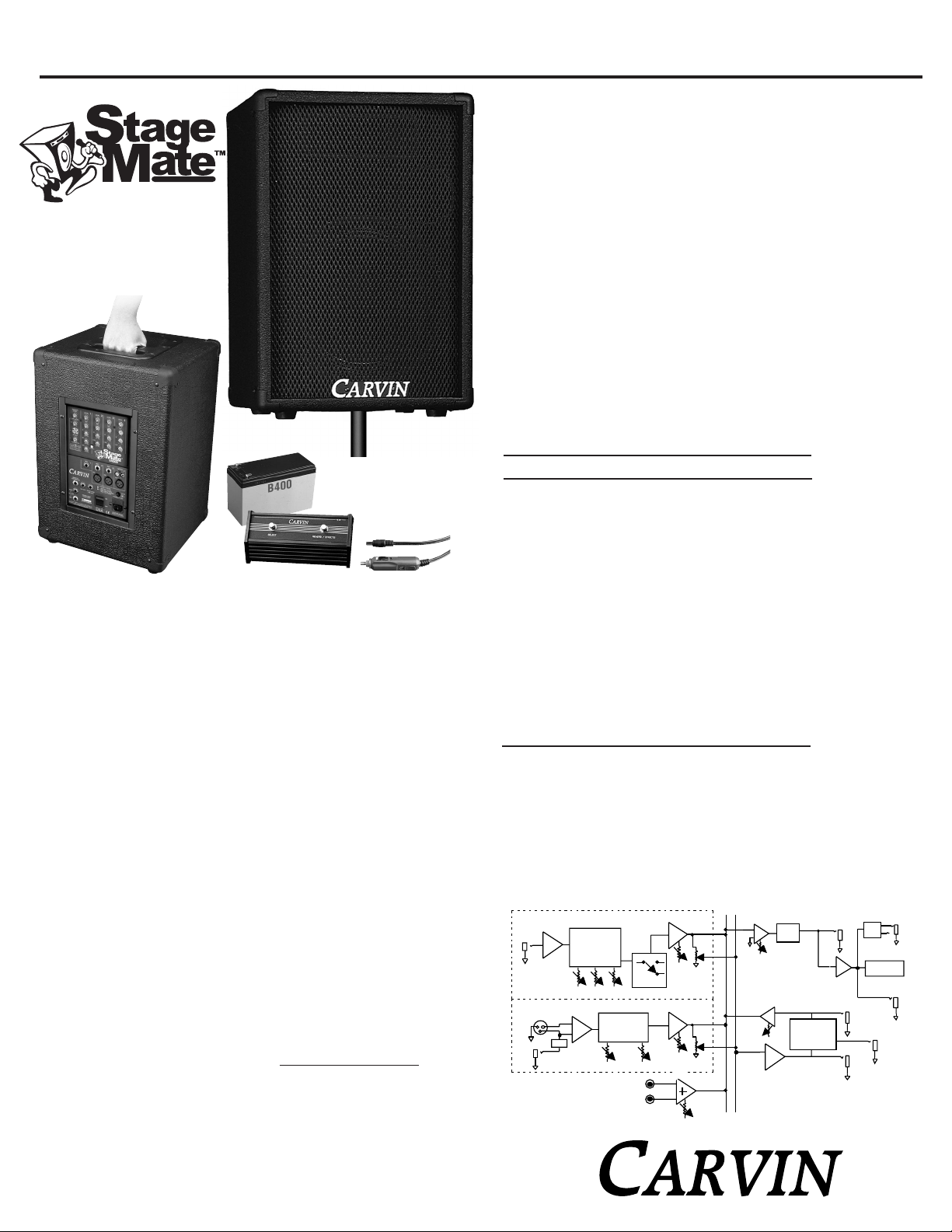
StageMate™ Block Diagram
• 100 Watts
• Battery Powered
• AC Powered
S400
S400D (with sound effects)
Note: Unit must be charged before use.
If unit is intermittent,recharge for 8 hours.
810 8Ω 200W extension speaker
FS22 Remote footswitch for effects
SS20 Speaker Stand
CM50
Professional mic
MS12 Mic Stand
C25 25’ 12V auto power cable
CV400 S400 vinyl cover
B400
To double your battery time, install a
second B400 (use as replacement)
OPTIONS:
B400
Replacement battery
FS22
Footswitch for effects
C25
25’ 12V auto cable
OPTIONS:
Page 2
1. CHANNEL CONTROL FUNCTIONS
LEVEL CONTROL
To start, turn the CHANNEL LEVEL control to 3 and the MASTER LEVEL to 3. As you require
more or less volume, turn the master up and down along with the channel level. If you need
more gain (sensitivity), you can turn the master and channel levels up to 10 together. However,
the channel should not be set at 10 and the master at 3 or distortion could result within the
pre-stages of your S400. Because all instrument and mics have different output levels, achieving full power from your S400 could happen at 5 or 10 on the levels controls.
EFFECTS SEND CONTROL
The EFF control on each channel is the “send” to add sound effects (built-in on the S400D
model). Normally you will set this control at 5 and the master EFF LEVEL at 5. Adjust accordingly to what sounds best. You should never have to run the channel send and the master
effects to 10. Do not set the channel effects at 10 & the master effects at 3 or distortion could
result within the effect processing circuits. These levels should be set about equal.
TONE CONTROLS - HI & LOW ( PLUS MID ON CH 1)
Tone controls are used to shape your sound. To start, set all tone controls to their center
0 position where no tone corrections are made. Generally for microphones you’ll want to
set the HI and LO controls to 3 o’clock (+6 db). This will add more depth and crispness
to your voice. You will want to do this for your instruments too. Channel 1 provides a MID
control for your guitar. Along with adding +6 db to the HI and LO controls, set the MID
control at 9 o’clock (-6db). This takes out the unwanted 750Hz mids which have a tendency to dull the sound of your guitar.
CHANNEL 1 ACOUSTIC SWITCH
The ACOUSTIC SWITCH is a high frequency boost set at 11K Hz for adding shimmering
highs for an acoustic instrument. Push this switch in when using acoustic instruments.
2. CHANNEL INPUT CONNECTORS
CHANNELS 2-4 MIC INPUTS
The MIC XLR connectors are designed for professional low impedance microphones. The
instrument jacks 2-3 may also be used at the same time providing the mic doesn’t have
an ON/OFF switch set to OFF. If a mic with an ON/OFF switch is used, such as Carvin’s
CM50, simply leave the switch in the ON position.
CHANNEL 1 INSTRUMENT JACK
The INST. 1 jack is designed for instruments such as an acoustic or electric guitar.
CHANNELS 2-4 INSTRUMENT JACK
The INST. jacks 2-4 are designed for instruments or line level inputs such as a drum machine,
tape deck, bass guitar, keyboard, an unbalanced mic, etc.. The sensitivity of these jacks
are lower than CH 1 so LEVELS 2-4 will have to be turned higher in some cases.
CHANNEL 4 L-R TAPE/CD RCA JACKS
The L-R TAPE / CD jacks are for connecting a tape deck or CD player to the StageMate™.
The jack is configured to combine the L and R inputs from your player. Adjust the level
with the Channel 4 LEVEL control. Some CD or tape players may have high output levels
and the Channel 4 LEVEL control must be kept very low. The XLR MIC input and RCA TAPE/CD
inputs may also be used simultaneously providing the mic doesn’t have an ON/OFF switch
set to OFF. If a mic with an ON/OFF switch is used, such as Carvin’s CM50, leave the switch
in the ON position.
3. MASTER FEATURES
MASTER LEVEL CONTROL
The MASTER LEVEL control adjusts the over all volume of the StageMate™, including the
Tape/CD, EFFects level and channels. Use this control to make overall adjustments. The
MASTER LEVEL should not be set much lower than the highest channel LEVEL.
EFFECTS LEVEL CONTROL
(EFFECTS RETURN LEVEL)
The EFF LEVEL control is the return volume for the effects loop and the internal DSP processor on the S400D model. To use your external effects processor, use the SEND and RETURN
jacks. To ensure that the effects processor is not being overdriven by the channel SEND
controls, the EFF LEVEL MASTER control should be not much lower than any of the channel EFF send levels. A normal setting for both the send and the master return effects should
be about 5.
EFFECT SELECT AND PARAMETER CONTROLS (S400D model)
The 24-BIT processor provides a host of great sounding effects including FLANGE,
REVERB, ECHO, & CHORUS. Turn up the LEVEL control to 5 as a starting position. Turn
the LEVEL higher if more effect signal is desired. The adjacent PK LED will flash if the EFF
LEVEL is set too high. To avoid distortion, lower the EFF LEVEL. Use the SELECT and the
ADJUST controls to get the desired effect (more details are below). Note: An audible noise
will be heard while adjusting the effects.
EFFECT PARAMETERS
Each of the four effects has a variable parameter that can be easily adjusted. Each “SELECT” &
“PARAMETER” is described below.
A) ECHO: SELECT the amount of the regeneration (repeating). Now select the ADJUST control for the shortest or longest delay time between the original signal and the echo.
B) REVERB: SELECT the amount of presence (high frequencies) in the reverb. Now turn the
ADJUST control to provide the minimum or maximum decay.
C) CHORUS: SELECT the amount of reverb with your chorus. Now turn the ADJUST control
to increase the depth.
D) FLANGE: SELECT the amount of speed with your flange (phasing effect). Now turn the
ADJUST control to increase the depth.
4. MASTER INPUT/OUTPUT CONNECTORS
EFFECTS FOOTSWITCH JACK
The EFFECTS FOOTSWITCH jack uses a normal 1/4” plug footswitch to turn off the effects
loop remotely. Use the Reverb/Effects switch on th optional Carvin FS22 footswitch.
EXTERNAL SPEAKER JACK
For additional coverage and output, connect the Carvin 810 speaker or any quality 8
ohm speaker system. NOTE: A 4 ohm extension speaker is not recommended or lower
battery time and distortion will result. Also, the added extension speaker will result
in lower battery time due to higher power demands delivered by the StageMate™. We
recommend installing the optional second “B400” battery to double your battery time.
HEADPHONE/LINE OUT JACK
This jack is a dual mono output for headphones or to feed the StageMate™ audio to an
external sound system. Use headphones with a STEREO 1/4” plug. Connecting headphones
or a cable does not mute the internal speaker. Use the MASTER LEVEL to adjust the volume
of this output.
EFFECTS SEND JACK
To use your outboard effects processor, connect this jack into the “input” of your effects
processor. The EFF level on each channel sends the signal to the processor from jack.
EFFECTS RETURN JACK
Connect the RET jack into the “output” of your external effects processor.
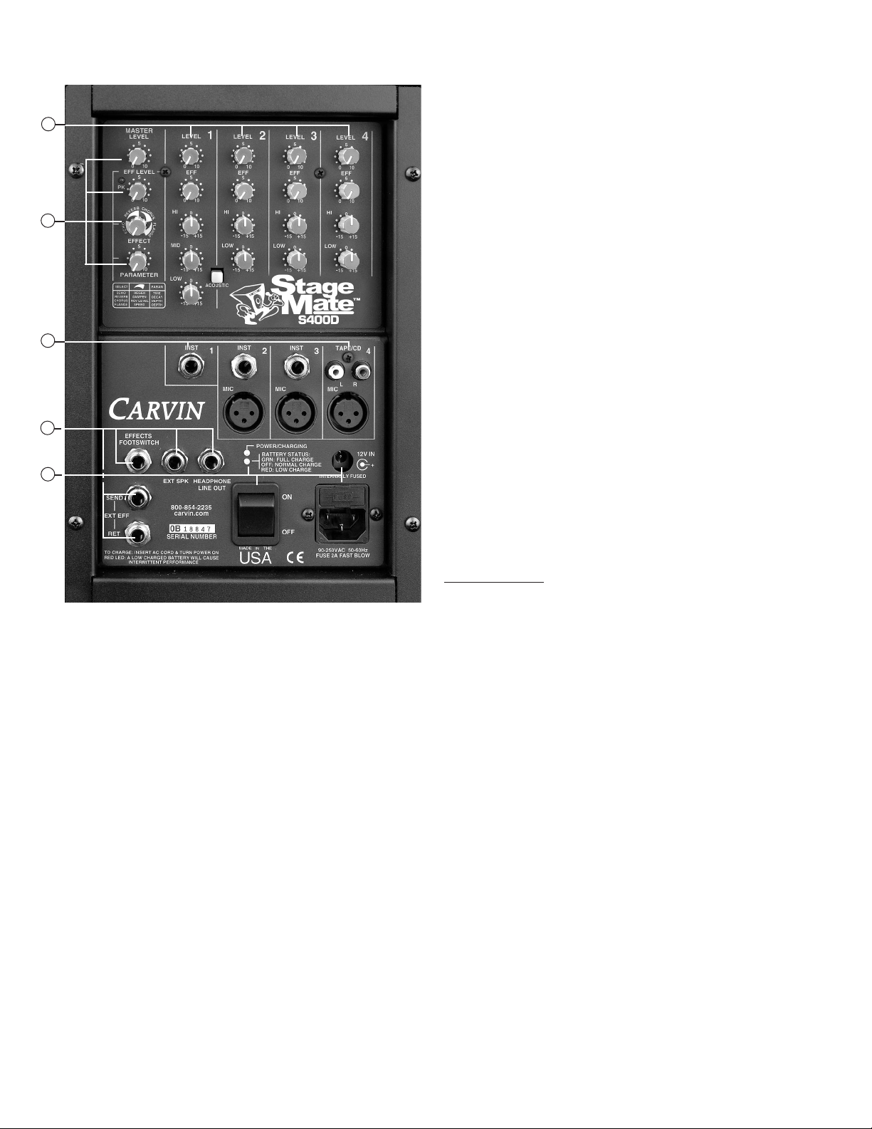
STAGEMATE™ REAR PANEL CONTROLS
1
3
2
4
5
Page 3

5. POWERING YOUR STAGEMATE™
AC POWER CORD
A detachable AC POWER CORD supplied is designed to operate and charge your
StageMate™. Securely insert the cord. Use only a grounded “3” prong” power source.
No attempt should ever be made to defeat or use the amp without the ground connected.
POWER SWITCH
The power switch is to be utilized as the master ON/OFF switch. To charge the internal
battery, plug the unit in and turn this switch “ON”.
CHARGING THE INTERNAL BATTERY
While using the StageMate™ on AC power, the battery is being charged. To charge while
not using be sure to leave the power switch in the “ON” position and turn the MASTER
LEVEL to 0. You may leave your StageMate™ on overnight. However, it is not recommended
to keep on for extended periods. The power LED indicates when the StageMate’s power
is on or charging. For battery operation, be sure that the battery is fully charged. It can
take up to 8 hours to recharge a dead battery (with dual batteries up to 16 hours). The maintenance-free lead acid battery does not have memory conditioning. However, if the battery is kept discharged, it can shorten the battery’s life.
BATTERY STATUS LED
The BATTERY STATUS LED is a two color LED indicating the battery voltage level. When
the LED is “GREEN”, the battery is at or very near full charge. When the LED is “off” the
battery has a normal charge. When the LED is “RED” the battery will need to be recharged.
Reducing volume levels will extend battery time. The unit may become intermittent in operation when the battery has a low charge.
12V DC JACK
The 12V jack is for connecting an external 12 volt DC power source such as an automo-
bile cigarette lighter to power and partially recharge the StageMate™. We recommend Carvin’s
C25 12V 25 ft cable adapter. Other adapters may be used, however, they must be at least
16 gauge wire and fused at 10 amps. Your car’s 12 volt battery will not fully charge the
StageMate™ unless you are running your engine–charging at 14 volts. Do not use this jack
if the DC voltage is over 14 volts. Do not use a “wall-wart” type supply to charge the
StageMate™. Instead use the StageMate's own internal charger by plugging the StageMate™
into AC power and turning the power switch “ON”.
AC FUSE REPLACEMENT
To check or replace the fuse, always turn off the power switch. To examine the fuse, remove
the power cord & place a screwdriver under the “FUSE” cap and pull the fuse holder out.
The fuse type is a 250V Slow Blow SB 5 x 20mm rated at 2A for 120V. Only a SLOW BLOW
(SB) type fuse will work. The fuse holder has room to store a spare fuse.
OPTIONS &
USAGE TIPS
Options
The bottom of the StageMate™ has a built in
stand insert and is ready to use with Carvin’s
SS20 Speaker Stand. The optional B400
battery kit is used as a battery replacement
or to double your battery running time. CV400
Cover is designed to protect against dust and
moisture. The C25 adapter allows you to connect to your 12 volt auto’s cigarette lighter.
FS22 footswitch remotely switches the effects
loop off & on. For hands free speech or
singing, use one of Carvin’s mic stands:
MS15 or MS12 (pictured).
The Optional 810 Extension Speaker
The optional 810 matching extension
speaker can be used to increase audience coverage. For performances
where the person(s) on stage needs to
hear and monitor their sound, the
StageMate™ and 810 extension speaker
can be slightly rotated to face inward at
the performer for onstage monitoring.
SS20
SPEAKER
STAND
MS12
MIC
STAND
Outdoor Events
The battery powered StageMate™ is ideal
for outdoor events including little league
games, beach parties and camping. The
Tape/CD inputs allows for the StageMate™
to become a portable Karaoke system.
The cabinet features Carvin’s durable
Duratex™ coating. The StageMate™
should be kept free from dirt and moisture to preserve proper function. Keep
the entire cabinet covered when not in
use. The optional CV400 is ideal for
protecting the StageMate™ from dust
when not in use.
ADD A SECOND BATTERY TO DOUBLE YOUR OPERATION TIME
The optional second B400 battery is recommended for longer operation at high
volume levels and when adding the 810 extension speaker.
1. To add the second battery, remove the 4 screws from the StageMates™ rear chassis and carefully remove the chassis from the cabinet. FIG 1
2. Observe the empty slot on the right bottom side of the cabinet and place the battery
into position and install the L bracket that comes with the B400 kit to hold the battery
in place.
3. The original battery on the left has spare terminals for connecting the second battery. Simply connect the supplied B400 battery wires to the negative and positive terminals on the original battery. Always match negative (-) to negative and positive (+)
to positive. Black is used for negative (-) and red for positive (+). Never allow a negative wire or terminal to touch a positive wire or terminal or “sparks will fly” with possible damage to the battery. If in doubt, please call our service department Mon. - Fri.
at 800-854-2235.
REPLACING THE BATTERY
After a few years of use, if you notice your operation time has been greatly reduced,
you will need to replace the battery as the cells may have weakened with age. The
B400 battery kit is shipped with connecting wires for use as a second battery. If you
are replacing your old battery, discard these wires as you will not need them.
A) To replace your battery, remove the 4 screws from the StageMate’s™ rear chassis
and carefully remove the chassis from the cabinet. FIG 1
B) Locate the battery mounted on the left side of the cabinet FIG 2 and remove the L
bracket. Simply pull the wires from the positive and negative battery terminals on the
old battery and reconnect your new battery (B400). Be sure to match negative (-) to
negative and positive (+) to positive. Black is used for negative (-) and red for positive
(+). Be sure not to short the battery terminals with a screwdriver or “sparks will fly” with
possible damage to the battery.
FIG 2 Cutaway view
-
+
-
+
b
l
a
c
k
r
e
d
b
la
c
k
r
e
d
black
re
d
-
+
-
+
b
la
c
k
re
d
black
red
black
red
FIG 1 Cutaway view
second battery
L bracket
L bracket
Controlling Feedback
Keep the mic away from the speaker to avoid
feedback. If feedback occurs, move your
speakers forward and your mic back so the
amplified sound isn’t picked up by the mic.
battery connection
wires (shipped with
B400 kit)
Page 4

CAUTION
RISK OF ELECTRIC SHOCK
DO NOT OPEN
SAFETY INSTRUCTIONS (EUROPEAN)
The conductors in the AC power cord are colored in accordance with the following code.
GREEN & YELLOW—Earth BLUE—Neutral BROWN—Live
U.K. MAIN PLUG WARNING: A molded main plug that has been cut off from the cord is
unsafe. NEVER UNDER ANY CIRCUMSTANCES SHOULD YOU INSERT A DAMAGED
OR CUT MAIN PLUG INTO A POWER SOCKET.
IMPORTANT! FOR YOUR PROTECTION, PLEASE READ THE FOLLOWING:
WATER AND MOISTURE: Appliance should not be used near water (near a bathtub, washbowl,
kitchen sink, laundry tub, in a wet basement, or near a swimming pool, etc). Care should be taken
so that objects do not fall and liquids are not spilled into the enclosure through openings.
POWER SOURCES: The appliance should be connected to a power supply only of the type described
in the operating instructions or as marked on the appliance.
GROUNDING OR POLARIZATION: Precautions should be taken so that the grounding or polarization means of an appliance is not defeated.
POWER CORD PROTECTION: Power supply cords should be routed so that they are not likely
to be walked on or pinched by items placed upon or against them, paying particular attention
to cords at plugs, convenience receptacles, and the point where they exit from the appliance.
SERVICING: The user should not attempt to service the appliance beyond that described in the
operating instructions. All other servicing should be referred to qualified service personnel.
FUSING: If your unit is equipped with a fuse receptacle, replace only with the same type fuse.
Refer to replacement text on the unit for correct fuse type.
REFER SERVICING TO QUALIFIED SERVICE PERSONNEL! THIS UNIT CONTAINS HIGH VOLTAGE INSIDE!
CAUTION
RISK OF ELECTRIC SHOCK
Ref. Des.
Carvin P/N Description
A1 60-45580 Op Amp MC4558
A10 60-45580 Op Amp MC4558
A2 60-45580 Op Amp MC4558
A3 60-45580 Op Amp MC4558
A4 60-45580 Op Amp MC4558
A5 60-45580 Op Amp MC4558
A6 60-45580 Op Amp MC4558
A7 60-45580 Op Amp MC4558
A8 60-45580 Op Amp MC4558
A9 60-45580 Op Amp MC4558
C1 45-82052 82PF 500V
C10 47-22051 22µF 50V
C100 46-10412 0.1µF 100V
C101 45-39052 39PF 500V
C102 47-22051 22µF 50V
C103 46-10212 0.001µF 100V
C104 46-10212 0.001µF 100V
C105 46-22312 0.022µF 100V
C106 47-22051 22µF 50V
C107 46-33212 0.0033µF 100V
C108 45-12152 120PF 500V
C109 47-22051 22µF 50V
C11 47-22051 22µF 50V
C110 45-39052 39PF 500V
C12 45-12152 120PF 500V
C13 45-12152 120PF 500V
C14 48-01031 1µF 35V
C15 47-10225 1000µF 25V
C16 47-22151 220µF 50V
C17 46-10312 0.01µF 100V
C18 47-22151 220µF 50V
C19 45-10551 0.1µF 50V
C2 47-22051 22µF 50V
C20 47-10225 1000µF 25V
C200 46-10412 0.1µF 100V
C201 45-82052 82PF 500V
C202 45-82052 82PF 500V
C203 47-22051 22µF 50V
C204 47-22051 22µF 50V
C205 45-27052 27PF 500V
C206 45-27052 27PF 500V
C207 47-22051 22µF 50V
C208 46-10412 0.1µF 100V
C209 46-10312 0.01µF 100V
C21 47-10225 1000µF 25V
C210 47-22051 22µF 50V
C211 45-39052 39PF 500V
C212 47-22051 22µF 50V
C213 45-12152 120PF 500V
C214 45-39052 39PF 500V
C23 42-47251 4700µF 50V
C24 42-47251 4700µF 50V
C25 46-10312 0.01µF 100V
C26 47-10061 10µF 63V
C27 47-10061 10µF 63V
C28 47-10061 10µF 63V
C29 45-10551 0.1µF 50V
C3 45-56152 560PF 500V
C30 45-10551 0.1µF 50V
C300 46-10412 0.1µF 100V
C301 45-82052 82PF 500V
C302 45-82052 82PF 500V
C303 47-22051 22µF 50V
C304 47-22051 22µF 50V
C305 45-27052 27PF 500V
C306 45-27052 27PF 500V
C307 47-22051 22µF 50V
C308 46-10412 0.1µF 100V
C309 46-10312 0.01µF 100V
C31 45-10551 0.1µF 50V
C310 47-22051 22µF 50V
C311 45-39052 39PF 500V
C312 47-22051 22µF 50V
C313 45-12152 120PF 500V
C314 45-39052 39PF 500V
C32 45-10551 0.1µF 50V
C33 45-10551 0.1µF 50V
C34 45-10551 0.1µF 50V
C35 45-10551 0.1µF 50V
C36 45-10551 0.1µF 50V
C37 47-10061 10µF 63V
C38 45-12152 120PF 500V
C39 41-47321 0.047µF 250 VAC
C4 45-56152 560PF 500V
C400 46-10412 0.1µF 100V
C401 45-82052 82PF 500V
C402 45-82052 82PF 500V
C403 47-22051 22µF 50V
C404 47-22051 22µF 50V
C405 45-27052 27PF 500V
C406 45-27052 27PF 500V
C407 47-22051 22µF 50V
C408 46-10412 0.1µF 100V
C409 46-10312 0.01µF 100V
C41 45-27052 27PF 500V
C410 47-22051 22µF 50V
C411 45-39052 39PF 500V
C412 47-22051 22µF 50V
C413 45-12152 120PF 500V
C414 45-39052 39PF 500V
C42 46-47312 0.047µF 100V
C43 47-22051 22µF 50V
C44 47-22051 22µF 50V
C45 47-22051 22µF 50V
C46 47-22051 22µF 50V
C5 47-22051 22µF 50V
C6 45-18152 180PF 500V
C7 47-22151 220µF 50V
C8 46-47412 0.47µF 63V
C9 47-22051 22µF 50V
D1 61-19140 1N914 HI SPD
D10 61-40030 1N4003
D11 61-40030 1N4003
D12 61-40030 1N4003
D13 61-40030 1N4003
D14 60-50200 Diode 3A 200V
D15 60-50200 Diode 3A 200V
D16 61-40030 1N4003
D17 61-40030 1N4003
D18 60-50200 Diode 3A 200V
D19 60-50200 Diode 3A 200V
D2 61-19140 1N914 HI SPD
D20 60-50200 Diode 3A 200V
D21 60-50200 Diode 3A 200V
D22 61-40030 1N4003
D23 61-40030 1N4003
D3 61-19140 1N914 HI SPD
D4 61-19140 1N914 HI SPD
D5 60-75340 Yellow small
D6 61-40030 1N4003
D7 60-75030 BiColor Rd:Grn
D8 60-50200 Diode 3A 200V
E1 25-22204 Rot Encoder Vert
H1 23-11008 8 Pin Vert
H10 23-11002 2 Pin Vert SHS
H11 23-11004 4 Pin Vert
H2 23-11002 2 Pin Vert SHS
H3 23-11004 4 Pin Vert
H4 23-11010 10 Pin Vert
H5 23-11004 4 Pin Vert
H6 23-11008 8 Pin Vert
H7 23-11004 4 Pin Vert
H8 23-15605 Header 5V Large
H9 23-15605 Header 5V Large
J1 21-50345 Ph Jack 3P Rean
J100 21-50345 Ph Jack 3P Rean
J2 21-50345 Ph Jack 3P Rean
J200 21-50345 Ph Jack 3P Rean
J201 21-40000 XLRF Neutrik
J3 21-50345 Ph Jack 3P Rean
J300 21-50345 Ph Jack 3P Rean
J301 21-40000 XLRF Neutrik
J4 21-40020 Phono Jack x2
J400 21-50345 Ph Jack 3P Rean
J401 21-40000 XLRF Neutrik
J5 21-50345 Ph Jack 3P Rean
J6 21-06457 7 Pin Plastic
J7 21-50345 Ph Jack 3P Rean
K1 70-05505 Relay 24V5A DPDT
K2 70-05505 Relay 24V5A DPDT
OP1 60-50253 Opto Isolator
P1 71-09063 B50K D Vrt 9m35 B
P100 71-09062 B50K-C D Vt 9/35B
P101 71-09062 B50K-C D Vt 9/35B
P102 71-09062 B50K-C D Vt 9/35B
P103 71-09063 B50K D Vrt 9m35 B
P104 71-09063 B50K D Vrt 9m35 B
P2 71-09063 B50K D Vrt 9m35 B
P200 71-09062 B50K-C D Vt 9/35B
P201 71-09062 B50K-C D Vt 9/35B
P202 71-09063 B50K D Vrt 9m35 B
P203 71-09063 B50K D Vrt 9m35 B
P3 71-09063 B50K D Vrt 9m35 B
P300 71-09062 B50K-C D Vt 9/35B
P301 71-09062 B50K-C D Vt 9/35B
P302 71-09063 B50K D Vrt 9m35 B
P303 71-09063 B50K D Vrt 9m35 B
P400 71-09062 B50K-C D Vt 9/35B
P401 71-09062 B50K-C D Vt 9/35B
P402 71-09063 B50K D Vrt 9m35 B
P403 71-09063 B50K D Vrt 9m35 B
PL1 21-00041 DC Power Socket
PL2 21-02804 Jack AC W/ Fuse
Q1 60-78151 7815 +15V3A
Q2 60-15006 MTP50N06
Q3 60-15006 MTP50N06
Q4 60-15006 MTP50N06
Q5 60-15006 MTP50N06
Q6 60-78150 7815 +15V
Q7 60-79150 7915 -15V
Q8 60-00014 Darlington NPN
QC1 06-40060 QC 90° Horizontal
QC10 06-40050 QC Vertical .250
QC11 06-40050 QC Vertical .250
QC12 06-40060 QC 90° Horizontal
QC13 06-40050 QC Vertical .250
QC14 06-40050 QC Vertical .250
QC2 06-40060 QC 90° Horizontal
QC3 06-40060 QC 90° Horizontal
QC4 06-40060 QC 90° Horizontal
QC5 06-40050 QC Vertical .250
QC6 06-40060 QC 90° Horizontal
QC7 06-40060 QC 90° Horizontal
QC8 06-40060 QC 90° Horizontal
QC9 06-40050 QC Vertical .250
R1 50-47025 470Ω
R10 50-15045 15K
R100 50-15055 150K
R101 50-30055 300K
R102 50-15035 1.5K
R103 50-10045 10K
R104 50-22045 22K
R105 50-47045 47K
R106 50-15035 1.5K
R107 50-10045 10K
R108 50-12045 12K
R109 50-22045 22K
R11 50-47025 470Ω
R110 50-15045 15K
R111 50-15035 1.5K
R12 50-47025 470Ω
R13 50-10045 10K
R14 55-03305 .33Ω 5W Wire
R15 50-22045 22K
R16 50-30035 3K
R17 54-10015 10Ω 2W
R18 53-47025 470Ω 1W
R19 53-47025 470Ω 1W
R2 50-22045 22K
R20 50-10045 10K
R200 50-22055 220K
R201 50-56231 5.62K
R202 50-56231 5.62K
R203 50-15055 150K
R204 50-15055 150K
R205 50-47035 4.7K
R206 50-82035 8.2K
R207 50-10055 100K
R208 50-47035 4.7K
R209 50-10035 1K
R21 50-10045 10K
R210 50-82035 8.2K
R211 50-10045 10K
R212 50-22045 22K
R213 50-15045 15K
R214 50-22041 22K 1%
R215 50-22041 22K 1%
R22 50-82035 8.2K
R23 50-82035 8.2K
R24 50-47035 4.7K
R25 50-10035 1K
R26 50-10035 1K
R27 50-15045 15K
R28 50-15045 15K
R29 50-82035 8.2K
R3 50-47025 470Ω
R30 50-10045 10K
R300 50-22055 220K
R301 50-56231 5.62K
R302 50-56231 5.62K
R303 50-15055 150K
R304 50-15055 150K
R305 50-47035 4.7K
R306 50-82035 8.2K
R307 50-10055 100K
R308 50-47035 4.7K
R309 50-10035 1K
R31 50-10015 10Ω
R310 50-82035 8.2K
R311 50-10045 10K
R312 50-22045 22K
R313 50-15045 15K
R314 50-22041 22K 1%
R315 50-22041 22K 1%
R32 50-56231 5.62K
R33 50-24045 24K
R34 50-15045 15K
R35 50-24045 24K
R36 55-05022 0.05Ω 5W Vert.
R37 50-10035 1K
R38 50-10035 1K
R39 50-10035 1K
R4 50-10035 1K
R40 50-10035 1K
R400 50-22055 220K
R401 50-56231 5.62K
R402 50-56231 5.62K
R403 50-15055 150K
R404 50-15055 150K
R405 50-47035 4.7K
R406 50-82035 8.2K
R407 50-10055 100K
R408 50-47035 4.7K
R409 50-10035 1K
R41 50-22035 2.2K
R410 50-82035 8.2K
R411 50-10045 10K
R412 50-22045 22K
R413 50-15045 15K
R414 50-22041 22K 1%
R415 50-22041 22K 1%
R42 50-30055 300K
R43 50-47055 470K
R44 50-47035 4.7K
R45 50-68025 680Ω
R46 50-15045 15K
R47 50-10045 10K
R48 50-10045 10K
R49 50-33045 33K
R5 50-10045 10K
R50 50-22065 2.2M
R51 50-10025 100Ω
R52 50-15025 150Ω
R53 50-22025 220Ω
R54 50-10035 1K
R6 50-10045 10K
R63 50-68045 68K
R7 50-47045 47K
R8 50-47045 47K
R9 50-10045 10K
S1 25-02201 DPDT Push Vert
S2 06-40040 SwitchAC DPST QCs
U1 60-72940 TDA7294
U2 60-35260 SG3526
Z1 61-04733 Zener 5.1V
Z2 61-47450 Zener 16V
Z3 61-47450 Zener 16V
REPLACEMENT PARTS LIST (for circuit cards)
This symbol is intended to
alert the user to the presence of uninsulated “dan-
gerous voltage” within the
product’s enclosure that may be of sufficient magnitude to constitute a risk of
electric shock to persons.
This symbol is
intended to alert the
user to the presence of
important operating
and maintenance (servicing) instructions in the literature accompanying
the appliance.
LIMITED WARRANTY
Your Carvin StageMate™ is guaranteed against failure for ONE YEAR unless otherwise stated. Carvin
will service and supply all parts at no charge to the customer providing the unit is under warranty.
Shipping costs are the responsibility of the customer. CARVIN DOES NOT PAY FOR PARTS OR SERVICING OTHER THAN OUR OWN. A COPY OF THE ORIGINAL INVOICE IS REQUIRED TO VERIFY YOUR
WARRANTY. Car vin assumes no responsibility for horn drivers or speakers damaged by this unit. This
warranty does not cover, and no liability is assumed, for damage due to: natural disasters, accidents,
abuse, loss of parts, lack of reasonable care, incorrect use, or failure to follow instructions. This warranty is in lieu of all other warranties, expressed or implied. No representative or person is authorized
to represent or assume for Carvin any liability in connection with the sale or servicing of Carvin products. CARVIN SHALL NOT BE LIABLE FOR INCIDENTAL OR CONSEQUENTIAL DAMAGES.
SERVICE: In the USA, please call 800-235-2235 for a RMA # (return authorization number). Write
this number on the box and enclose a description of the problem. Prepay to Carvin 12340 World Trade
Drive, SD, CA 92128.
Outside the USA, contact your dealer or go to http://www
.carvinworld.com for your nearest service
center. Include a written description of the problem with serial number and date of purchase.
HELP SECTION
1) StageMate™ WILL NOT TURN ON
Check the power to the StageMate™. Check for tripped circuit breakers, unplugged extension cords
or power-strip switches that may be turned off. Check the fuse. If a dark brownish color or no wire
can be seen within the glass tube, then replace. The amp may be perfectly fine but occasionally a
fuse may blow because of high AC voltage surges. However, after the fuse has been replaced with
the proper Slow Blow value and if the fuse fails again, the amp will require servicing.
2) MAINTENANCE
To bring back the new look, your StageMate™ cabinet can be washed with mild detergent and/or a
warm damp soft cloth. This will remove normal dust and oil from the front and back panels. Never
spray cleaners or detergents directly at the units electronic controls. It is recommended to keep
the StageMate™ free from dust, dirt, and moisture as much as possible.
 Loading...