

Page 1
CAUTION
RISK OF ELECTRIC SHOCK
DO NOT OPEN
SAFETY INSTRUCTIONS (EUROPEAN)
The conductors in the AC power cord are colored in accordance with the following code.
GREEN & YELLOW—Earth BLUE—Neutral BROWN—Live
U.K. MAIN PLUG WARNING: Amolded main plug that has been cut off from the cord is
unsafe. NEVER UNDER ANY CIRCUMSTANCES SHOULD YOU INSERT A DAMAGED OR CUT MAIN PLUG INTO APOWER SOCKET.
IMPORTANT! FOR YOUR PROTECTION, PLEASE READ THE FOLLOWING:
WATER AND MOISTURE: Appliance should not be used near water (near a bathtub, washbowl,
kitchen sink, laundry tub, in a wet basement, or near a swimming pool, etc). Care should be taken
so that objects do not fall and liquids are not spilled into the enclosure through openings.
POWER SOURCES: The appliance should be connected to a power supply only of the type
described in the operating instructions or as marked on the appliance.
GROUNDING OR POLARIZATION: Precautions should be taken so that the grounding or polarization means of an appliance is not defeated.
POWER CORD PROTECTION: Power supply cords should be routed so that they are not likely to
be walked on or pinched by items placed upon or against them, paying particular attention to
cords at plugs, convenience receptacles, and the point where they exit from the appliance.
SERVICING: The user should not attempt to service the appliance beyond that described in the
operating instructions. All other servicing should be referred to qualified service personnel.
FUSING: If your unit is equipped with a fuse receptacle, replace only with the same type fuse.
Refer to replacement text on the unit for correct fuse type.
REFER SERVICING TO QUALIFIED SERVICE
PERSONNEL! THIS UNIT CONTAINS HIGH
VOLTAGE INSIDE!
CAUTION
RISK OF ELECTRIC SHOCK
D6 03-50135 1 EACH STANDOFF LED .500 X .135 T1
D7 03-50135 1 EACH STANDOFF LED .500 X .135 T1
S1 06-40040 4 EACH TERMINAL VERT FEML PC MTG .250
QC5 06-40050 1 EACH TERMINAL VERT MALE PC MTG .250
QC1 06-40060 2 EACH TERMINAL 90dg MALE PC MTG .250
QC2 06-40060 2 EACH TERMINAL 90dg MALE PC MTG .250
J11 21-40000 6 EACH XLR FEML CON NEUTRIK #NC3FAV-0
J21 21-40000 6 EACH XLR FEML CON NEUTRIK #NC3FAV-0
J31 21-40000 6 EACH XLR FEML CON NEUTRIK #NC3FAV-0
J41 21-40000 6 EACH XLR FEML CON NEUTRIK #NC3FAV-0
J51 21-40000 6 EACH XLR FEML CON NEUTRIK #NC3FAV-0
J61 21-40000 6 EACH XLR FEML CON NEUTRIK #NC3FAV-0
J5 21-40022 1 EACH JACK RCA QUAD PC VERTICAL MTG
J1 21-50345 “11 EACH JACK .250”” PHONE MONO PCB MTG”
J2 21-50345 “11 EACH JACK .250”” PHONE MONO PCB MTG”
J3 21-50345 “11 EACH JACK .250”” PHONE MONO PCB MTG”
J4 21-50345 “11 EACH JACK .250”” PHONE MONO PCB MTG”
J6 21-50345 “11 EACH JACK .250”” PHONE MONO PCB MTG”
J12 21-50345 “11 EACH JACK .250”” PHONE MONO PCB MTG”
J22 21-50345 “11 EACH JACK .250”” PHONE MONO PCB MTG”
J32 21-50345 “11 EACH JACK .250”” PHONE MONO PCB MTG”
J42 21-50345 “11 EACH JACK .250”” PHONE MONO PCB MTG”
J52 21-50345 “11 EACH JACK .250”” PHONE MONO PCB MTG”
J62 21-50345 “11 EACH JACK .250”” PHONE MONO PCB MTG”
F1 23-03529 2 EACH FUSEHOLDER CLIPS 3AG VERT MTG
“H2, H4, H5, H6, H7, H8”
23-11004 6 EACH CONNECT HEADER 4 PIN STRAIGHT
“H1, H10, H11, H12”
23-11008 4 EACH CONNECT HEADER 8 PIN STRAIGHT
“H13, H14” 23-11010
2 EACH CONNECT HEADER 10 PIN STRAIGHT
H9 23-15605 “1 EACH CONNECT HEADER .156”” 5 PIN”
H3 23-40008 1 EACH CONNECT HEADER .400 IN 8 PIN
H3 middle pins 23-92995
2 EACH SHUNT JUMPER UNPLATED
“S4, S11, S21, S31, S41, S51, S61”
25-02201- 1 * STD 7 EACH ASSEMBLED
SWITCH AND CAP
AA 30-62004 1 EACH PCB CARD SYS MSTR PA620/410
“C58, C98” 42-47251“1 * STD 2 EACH CAP ELEC 4,700 MFD 50V 20%”
C150 or C250 46-22461
1 EACH CAP MYLR .2200UF 63VOLT 10%
“C14, C15, C61, C70, C84, C85, C94”
47-10225 “7 EACH CAP ELEC 1,000 MFD 25V 20%”
“C49, C51, C53, C71, C111, C117, C123, C211, C223, C311, C323,
C411, C423, C511, C523, C611, C623”
49-10212 17 EACH 0.001UF SMT 10% FILM 0805 50V
“C27, C40, C43, C57, C95”
49-10312 5 EACH 0.01UF SMT 10% FILM 080550V
“C3, C4, C7, C10, C11, C12,”
49-10412 23 EACH 0.1UF SMT 5% CERAMIC 0805
“C13, C24, C35, C39, C60, C65,”
49-10412 23 EACH 0.1UF SMT 5% CERAMIC 0805
“C74, C75, C76, C77, C78, C79,”
49-10412 23 EACH 0.1UF SMT 5% CERAMIC 0805
“C80, C142, C151, C152, C155”
49-10412 23 EACH 0.1UF SMT 5% CERAMIC 0805
“C42, C44, C99” 49-10451
3 EACH 0.1 uF SMT 10% FILM 1206 50V
“C2, C5, C16, C19, C20, C21,”
49-22035 58 EACH SMT CAP 22uF 35v ELECTROLITIC
“C22, C26, C29, C31, C34, C56,”
49-22035 58 EACH SMT CAP 22uF 35v ELECTROLITIC
“C59, C62, C63, C64, C66, C67,”
49-22035 58 EACH SMT CAP 22uF 35v ELECTROLITIC
“C68, C93, C103, C104, C105, C108,”
49-22035 58 EACH SMT CAP 22uF 35v ELECTROLITIC
“C110, C114, C153, C154,”
49-22035 58 EACH SMT CAP 22uF 35v ELECTROLITIC
“C203, C204, C205, C208, C210, C214,”
49-22035 58 EACH SMT CAP 22uF 35v ELECTROLITIC
“C303, C304, C305, C308, C310, C314,”
49-22035 58 EACH SMT CAP 22uF 35v ELECTROLITIC
“C403, C404, C405, C408, C410, C414,”
49-22035 58 EACH SMT CAP 22uF 35v ELECTROLITIC
“C503, C504, C505, C508, C510, C514,”
49-22035 58 EACH SMT CAP 22uF 35v ELECTROLITIC
“C603, C604, C605, C608, C610, C614,”
49-22035 58 EACH SMT CAP 22uF 35v ELECTROLITIC
“C72, C122, C124, C135”
49-22212 4 EACH 0.0022UF SMT 10% FILM 0805 50V
“C50, C112, C134, C212, C312, C412, C512, C612”
49-22312 8 EACH 0.022UF SMT 10% FILM 0805 50V
“C8, C9” 49-25152
2 EACH 220PF SMT 5% CERAMIC 0805
“C8, C9”
“C1, C36, C37, C106, C107,”
49-27052 16 EACH 27 PF SMT 5% CERAMIC 0805
“C206, C207, C209, C306, C307,”
49-27052 16 EACH 27 PF SMT 5% CERAMIC 0805
“C406, C407, C506, C507, C606, C607”
49-27052 16 EACH 27 PF SMT 5% CERAMIC 0805
C55 49-33152 1 EACH 330PF SMT 5% CERAMIC 0805
C47 49-33212 1 EACH 0.0033UF SMT 10% FILM 0805 50
“C38, C48” 49-33312
2 EACH 0.033UF SMT 10% FILM 0805 50V
“C17, C18, C23, C25, C28, C33,”
49-39052 24 EACH 39PF SMT 5% CERAMIC 0805
“C69, C82, C87, C90, C100, C109,”
49-39052 24 EACH 39PF SMT 5% CERAMIC 0805
“C113, C118, C119, C213, C309, C313,”
49-39052 24 EACH 39PF SMT 5% CERAMIC 0805
“C409, C413, C509, C513, C609, C613”
49-39052 24 EACH 39PF SMT 5% CERAMIC 0805
“C45, C52, C54” 49-47212
3 EACH 0.0047uF SMT FILM 0805 50V
“C32, C46, C73” 49-47312
2 EACH 0.047UF SMT 10% FILM 0805 50V
“C30, C41, C101, C102, C201, C202, C301,”
49-82052 14 EACH 82PF SMT 5% CERAMIC 0805
“C302, C401, C402, C501, C502, C601, C602”
49-82052 14 EACH 82PF SMT 5% CERAMIC 0805
“R222, R224” 58-92201
2 EACH 22 SMT 1W 2512 20%
“R59, R60, R89, R128”
55-03300 4 EACH RES .33 OHM 5W 5% SB VERT
R196 58-00035 1 EACH 0.0 SMT JUMPER 1206
“R85, R91, R165, R171, R172, R188, R189”
58-10015 7 EACH 10.5 SMT .25W 1206 1%
R40 58-10025 1 EACH 100.5 SMT .25W 1206 1%
“R48, R66, R78, R81, R86, R99,”
58-10035 15 EACH 1K SMT .25W 1206 1%
“R111, R131, R133, R136, R150, R158,”
58-10035 15 EACH 1K SMT .25W 1206 1%
“R187, R190, R191”
58-10035 15 EACH 1K SMT .25W 1206 1%
“R1, R4, R28, R29, R30,”
58-10045 39 EACH 10K SMT .25W 1206 1%
“R31, R35, R36, R37, R39,”
58-10045 39 EACH 10K SMT .25W 1206 1%
“R83, R116,” 58-10045
39 EACH 10K SMT .25W 1206 1%
“R120, R121, R123, R139,”
58-10045 39 EACH 10K SMT .25W 1206 1%
“R152, R153, R154, R156, R159, R160,”
58-10045 39 EACH 10K SMT .25W 1206 1%
“R167, R170, R175, R176, R193,”
58-10045 39 EACH 10K SMT .25W 1206 1%
“R198, R199, R216, R223, R316,”
58-10045 39 EACH 10K SMT .25W 1206 1%
“R323, R416, R423,”
58-10045 39 EACH 10K SMT .25W 1206 1%
“R516, R523, R616, R623”
58-10045 39 EACH 10K SMT .25W 1206 1%
“R52, R61, R71, R100, R134, R135, R138”
58-10055 7 EACH 100K SMT .25W 1206 1%
“R92, R94, R144” 58-10065
3 EACH 1M SMT .25W 1206 1%
“R112, R115, R212, R215, R312, R315,”
58-15035 12 EACH 1.5K SMT .25W 1206 1%
“R412, R415, R512, R515, R612, R615”
58-15035 12 EACH 1.5K SMT .25W 1206 1%
“R38, R105, R125, R205,”
58-15045 8 EACH 15K SMT .25W 1206 1%
“R305, R405, R505, R605”
58-15045 8 EACH 15K SMT .25W 1206 1%
“R2, R8, R41, R44,”
58-15055 8 EACH 150K SMT .25W 1206 1%
“R54, R65, R67, R79”
58-15055 8 EACH 150K SMT .25W 1206 1%
“R76, R130, R137”58-22025
3 EACH 220.5 SMT .25W 1206 1%
“R21, R27, R32, R47, R53, R55, R56,”
58-22035 36 EACH 2.2K SMT .25W 1206 1%
“R62, R64, R68, R72, R74, R95, R97,”
58-22035 36 EACH 2.2K SMT .25W 1206 1%
“R103, R104, R124, R142, R155, R157,”
58-22035 36 EACH 2.2K SMT .25W 1206 1%
“R169, R203, R204, R303, R304,”
58-22035 36 EACH 2.2K SMT .25W 1206 1%
“R403, R404, R503, R504, R603, R604,”
58-22035 36 EACH 2.2K SMT .25W 1206 1%
“R117, R217, R317, R417, R517, R617”
58-22035 36 EACH 2.2K SMT .25W 1206 1%
“R5, R10, R11, R12, R14,”
58-22045 41 EACH 22K SMT .25W 1206 1%
“R15, R16, R18, R19, R23,”
58-22045 41 EACH 22K SMT .25W 1206 1%
“R24, R25, R26, R33,”
58-22045 41 EACH 22K SMT .25W 1206 1%
“R108, R109, R113, R126, R127, R129,”
58-22045 41 EACH 22K SMT .25W 1206 1%
“R132, R137, R140, R141, R148, R149, R163,”
58-22045 41 EACH 22K SMT .25W 1206 1%
“R208, R209, R213, R308, R309, R313,”
58-22045 41 EACH 22K SMT .25W 1206 1%
“R408, R409, R413, R508, R509, R513,”
58-22045 41 EACH 22K SMT .25W 1206 1%
“R608, R609, R613”
58-22045 41 EACH 22K SMT .25W 1206 1%
“R20, R22, R63, R69, R73, R75”
58-22055 6 EACH 220K SMT .25W 1206 1%
“R50, R90” 58-27025
2 EACH 270.5 SMT .25W 1206 1%
“R77, R82, R161, R162, R177, R178, R233”
58-33025 7 EACH 330.5 SMT .25W 1206 1%
“R70, R106, R107, R168, R206,”
58-33035 14 EACH 3.3K SMT .25W 1206 1%
“R207, R306, R307, R406, R407,”
58-33035 14 EACH 3.3K SMT .25W 1206 1%
“R506, R507, R606, R607”
58-33035 14 EACH 3.3K SMT .25W 1206 1%
“R3, R9, R34, R145”
58-33045 * STD 4 EACH 33K SMT .25W 1206 1%
“R48, R58, R88, R200”
58-47015 4 EACH 47.5 SMT .25W 1206 1%
“R42, R43, R45, R80, R93, R98, R146”
58-47025 7 EACH 470.5 SMT .25W 1206 1%
“R6, R13, R17, R84,”
58-47035 22 EACH 4.7K SMT .25W 1206 1%
“R110, R118, R119, R210, R218, R219,”
58-47035 22 EACH 4.7K SMT .25W 1206 1%
“R310, R318, R319, R410, R418, R419,”
58-47035 22 EACH 4.7K SMT .25W 1206 1%
“R510, R518, R519, R610, R618, R619”
58-47035 22 EACH 4.7K SMT .25W 1206 1%
“R46, R57, R87, R96, R114,”
58-47045 13 EACH 47K SMT .25W 1206 1%
“R147, R164, R166, R214”
58-47045 13 EACH 47K SMT .25W 1206 1%
“R314, R414, R514, R614”
58-47045 13 EACH 47K SMT .25W 1206 1%
R92 58-47055 1 EACH 470K SMT .25W 1206 1%
R7 58-56025 1 EACH 560.5 SMT .25W 1206 1%
“R101, R102, R201, R202, R301, R302,”
58-56035 12 EACH 5.6K SMT .25W 1206 1%
“R401, R402, R501, R502, R601, R602”
58-56035 12 EACH 5.6K SMT .25W 1206 1%
“R173, R174, R192, R193, R194, R195”
58-68015 6 EACH 68.5 SMT .25W 1206 1%
“R49, R51, R151” 58-68025
3 EACH 680 SMT .25W 1206 1%
R122 58-68035 1 EACH 6.8K SMT .25W 1206 1%
“R142, R143” 58-91025
2 EACH 910.5 SMT .25W 1206 1%
“Q32, Q34” 60-00142
2 EACH TRANS NPN TIP142 TO-218
“Q31, Q33” 60-00147
2 EACH TRANS PNP TIP147 TO-218
“D31, D32, D33, D34”
60-50200 4 EACH DIODE GEN REC 1N5402 3A 200V
“Q2, Q11, Q23, Q25”
60-55500- 1 * STD 4 EACH TRANS 2N5550
HV NPN 250V T0-92
U3 60-71024 1 EACH CMOS STATIC RAM 1MEG 20NS
D6 60-75320 1 EACH LED RED DIFFUSED 3MM T-1.00
D1 60-75330 1 EACH LED GREEN DIFFUSED 3MM T-1.00
D2 60-75340 1 EACH LED YELLOW DIFFUSED 3MM T-1.00
Q27 60-78050 1 EACH REGULATOR VOLTAGE 5 +V 1 AMP
Q14 62-04391 1 EACH TRANSISTOR SMT MMBF4391LT1
“Z1, Z2, Z3, Z4, Z11, Z12, Z13”
62-04739 7 EACH SMT DIODE ZENER 4739
“D15, D16, D17, D18, D35, D36”
62-06001 6 EACH DIODE ULTRA FAST 600V 1A SMA
U1 62-07712 1 EACH IC DSP W/CODEC AKM7712
Y1 62-16400 1 EACH CRYSTAL CERAMIC SMT 16.4mHz
“D3, D4, D5, D7, D8, D9,”
62-19140 11 EACH 1N914 HI SPD SMT 250mW DIODE
“D10, D11, D12, D13, D14”
62-19140 11 EACH 1N914 HI SPD SMT 250mW DIODE
“A10, A11, A21, A31, A41, A51, A61”
62-20430 7 EACH NJM2043SMT(TESTED) DUAL HFREQ
“A1, A2, A3, A4, A5, A7,”
62-45650 16 EACH NJM4565 SMT DUAL HI FREQ
“A8, A9, A12, A15, A16,”
62-45650 16 EACH NJM4565 SMT DUAL HI FREQ
“A22, A32, A42, A52, A62”
62-45650 16 EACH NJM4565 SMT DUAL HI FREQ
“Q3, Q4, Q5, Q6, Q9, Q10, Q13, Q16, Q17, Q18, Q21, Q24”
62-54001 12 EACH MMBT5401LTI PNP SOT-23 SMT
“Q7, Q8, Q19, Q20”
62-55500 4 EACH MMBT5550 NPN SOT-23
U2 62-87764 1 EACH MICRO CONTROLLER SOIC PACKAGE
“K1, K2” 70-05713
2 EACH RELAY SPDT 12A@120VAC/24V COIL
F1 70-21050 1 EACH FUSE ABC 5.00A FAST 6.35X32MM
“P11, P13, P21, P23, P31, P33,”
71-09252 “12 EACH POT 9 “”D-P”” 25F B50K-CC”
“P41, P43, P51, P53, P61, P63”
71-09252 “12 EACH POT 9 “”D-P”” 25F B50K-CC”
“P1, P2, P3, P8, P9, P10,”
71-09253 “24 EACH POT 9 “”D-P”” 25F B50K-”
“P14, P16, P17, P24, P26, P27,”
71-09253 “24 EACH POT 9 “”D-P”” 25F B50K-”
“P34, P36, P37, P44, P46, P47,”
71-09253 “24 EACH POT 9 “”D-P”” 25F B50K-”
“P54, P56, P57, P64, P66, P67”
71-09253 “24 EACH POT 9 “”D-P”” 25F B50K-”
“P72, P73, P74, P75, P76, P77, P78”
71-10320 7 EACH FADER 20MM SL20V3-B10K-L15D(G)
REPLACEMENT PARTS LIST (for circuit cards)
This symbol is intended to
alert the user to the presence of uninsulated “dan-
gerous voltage” within the
product’s enclosure that may be of sufficient magnitude to constitute a risk of
electric shock to persons.
This symbol is intended to alert the user to
the presence of important operating and
maintenance (servicing) instructions
in the literature accompanying the
appliance.
LIMITED WARRANTY
Your Carvin product is guaranteed against failure for 1 YEAR unless otherwise stated.
Carvin will service and supply all parts at no charge to the customer providing the unit is
under warranty. Shipping costs are the responsibility of the customer. CARVIN DOES NOT
PAY FOR PARTS OR SERVICING OTHER THAN OUR OWN. A COPY OF THE ORIGINAL
INVOICE IS REQUIRED TO VERIFY YOUR WARRANTY. Carvin assumes no responsibility
for horn drivers or speakers damaged by this unit. This warranty does not cover, and no
liability is assumed, for damage due to: natural disasters, accidents, abuse, loss of parts,
lack of reasonable care, incorrect use, or failure to follow instructions. This warranty is in
lieu of all other warranties, expressed or implied. No representative or person is authorized
to represent or assume for Carvin any liability in connection with the sale or servicing of
Carvin products.
CARVIN SHALL NOT BE LIABLE FOR INCIDENTAL OR CONSEQUENTIAL
DAMAGES.
When RETURNING merchandise to the factory, you may call for a return authorization
number. Describe in writing each problem. If your unit is out of warranty, you will be
charged the current FLAT RATE for parts and labor to bring your unit up to factory specifications.
MAINTAINING YOUR EQUIPMENT
Avoid spilling liquids or allowing any other foreign matter inside the unit. The panel of
your unit can be wiped from time to time with a dry or slightly damp cloth in order to
remove dust and bring back the new look.
As with all pro gear, avoid prolonged use in
caustic environments (salt air). When used in such an environment, be sure the mixer
is adequately protected by a cover.
Page 2
12340 World Trade Drive, San Diego, CA 92128
800.854.2235 www.carvin.com
Congratulations on your purchase of the PA410 or PA620 mixer! These mixers are
the culmination of Carvin’s 50 years of knowledge and experience in the pro sound
arena. The quality and features included in these powerful little units make them revolutionary and unheard of in their price range! Please take the time to review this
manual so that you may fully enjoy all the benefits your mixer has to offer.
PRO FEATURES
The PA series mixers give you pro XLR mic preamps, along with 1/4" line inputs on every
channel. Phantom power is provided on the XLR inputs for compatibility with high quality
condenser mics. Each channel also provides a MONITOR send, a GAIN switch for accommodating low and high input signals, EFFECTS send and LEVEL control.
ACTIVE EQ
Each channel of the PA series provides a HI and LOW shelving EQ with ±12dB of adjustment range featuring an internally optimized midrange circuit, for easy, effective tone
adjustments that sound great for vocals.
BUILT-IN POWER AMPS
The amplifiers in the PA series mixers are powerful enough to easily drive your speakers
for excellent coverage and clean, punchy sound. The PA410 delivers 100 Watts RMS,
while the more powerful PA620 delivers 200 Watts RMS! (Note: Each model is designed
to be used with 8Ω speakers (not 4 Ω). If the relay protection engages after 20 minutes
of heavy use (no output from the mixer while the power LED is on), you are using 4Ω
speakers. If the mixer goes into protect, let the mixer cool down and it will reset).
24-BIT DIGITAL PROCESSOR
Perhaps the most incredible feature of the PA series mixer is the "Full-Featured" 24-Bit Digital
Processor. You get awesome lush Reverbs, rich Chorus, crisp Delay and Echo, and thick,
layered Flanging – all with full band-width and pristine clarity. And with the PARAMETER
control, you can continuously modify each effect for up to 64 different sounds for a total of
256 effects! Nobody else has offered these features in a mixer in this price range!
MASTER SECTION
The master section of the PA series provides a MAIN volume for controlling your over-all
mix volume. A master MONITOR knob lets you control the over-all volume of an external monitor amp. The TAPE IN control is for varying the level of the signal being received
at the RCA TAPE IN jacks. A PHANTOM POWER switch is provided for engaging or disengaging power to condenser mics. Three controls EFFECT, SELECT, and PARAMETER,
are for setting up the full-featured Digital Effects. Finally, there is a master 7-Band
GRAPHIC EQ for fine tuning your over-all mix. It’s so easy to get a great sound!
CONNECTIVITY
The PA series mixers allow easy connections to most related equipment. There is a 1/4"
MAIN LINE OUT for sending the main signal to an external power amp or for plugging in
headphones. The MONITOR OUT is a 1/4" jack for feeding an external monitor amplifier.
RCA TAPE IN and OUT are provided for easy connection to keyboards, tape decks, CD
players, MiniDisc, computers, etc. The EFFECTS FOOT SW jack allows the connection of
the optional FS22 or equivalent footswitch for turning on or off your effects during performances. Two 1/4" SPEAKER jacks provide quick, easy connection for two 8 Ohm
speakers.
CONSTRUCTION
Solid plywood construction, space-age aluminum chassis and a modern power supply all add
up to make the PA series the best-built and most lightweight, compact pro mixers available.
Technical advances like SMT (surface mount components) and incredible 24-Bit DSP ensure
that they are the best sounding and most reliable compact mixers as well.
RECEIVING INSPECTION—read before getting started
INSPECT YOUR MIXER FOR ANY DAMAGE which may have occurred during shipping.
If any damage is found, please notify the shipping company and CARVIN immediately.
SAVE THE CARTON & ALL PACKING MATERIALS. In the event you have to re-ship your
unit, always use the original carton and packing material. This will provide the best possible protection during shipment. CARVIN and the shipping company are not liable for
any damage caused by improper packing.
SAVE YOUR INVOICE. It will be required for warranty service if needed in the future.
SHIPMENT SHORTAGE. If you find items missing, they may have been shipped sepa-
rately. Please allow several days for the rest of your order to arrive before inquiring.
RECORD THE SERIAL NUMBER on the enclosed warranty card or below on this manual for your records. Keep your portion of the card and return the portion with your
name and comments to us or register online at www.carvin.com/registration
For your records, you may wish to record the following information.
Serial No._____________________ Invoice Date_______________
PA620
76-41620A 0101
PA410 / PA620 SPECIFICATIONS:
Frequency Response: 20Hz-20KHz ±1dB
Total Harmonic Distortion: Less than 1%
Equivalent Input Noise: 150 ohm source: -110dBu
Output Noise: -90dBu Master Line Out
(all levels minimum)
Output Power: PA410 4Ω: 100 watts RMS
PA620 4Ω: 200 watts RMS
Output Headroom: +20dB 1/4” unbalanced
Maximum Gain: Mic in to Master Line Out: 65dB
Crosstalk: Adjacent ch’s: -60db at 1KHz
Common Mode Rejection: -75db at 1KHz
Phantom Power: All XLR Mic in channels
Channel EQ.: HI: 12KHz ±15dB
LOW: 85Hz ±15dB
Graphic EQ.: 7 Band Oct. Intervals ±12dB
100, 250, 1k, 2.5k, 5k, 10k
Mic Input: Balanced XLR input
Line Input: Unbalanced 1/4” Phone Jack
Power Requirements: PA410 120 or 240 VAC - 110VA
PA620 120 or 240 VAC - 220VA
Size: 16”W x8”D x 8.25”H
Weight: PA410: 15lbs., PA620: 18lbs
Options: FS22 Footswitch, CV620 cover
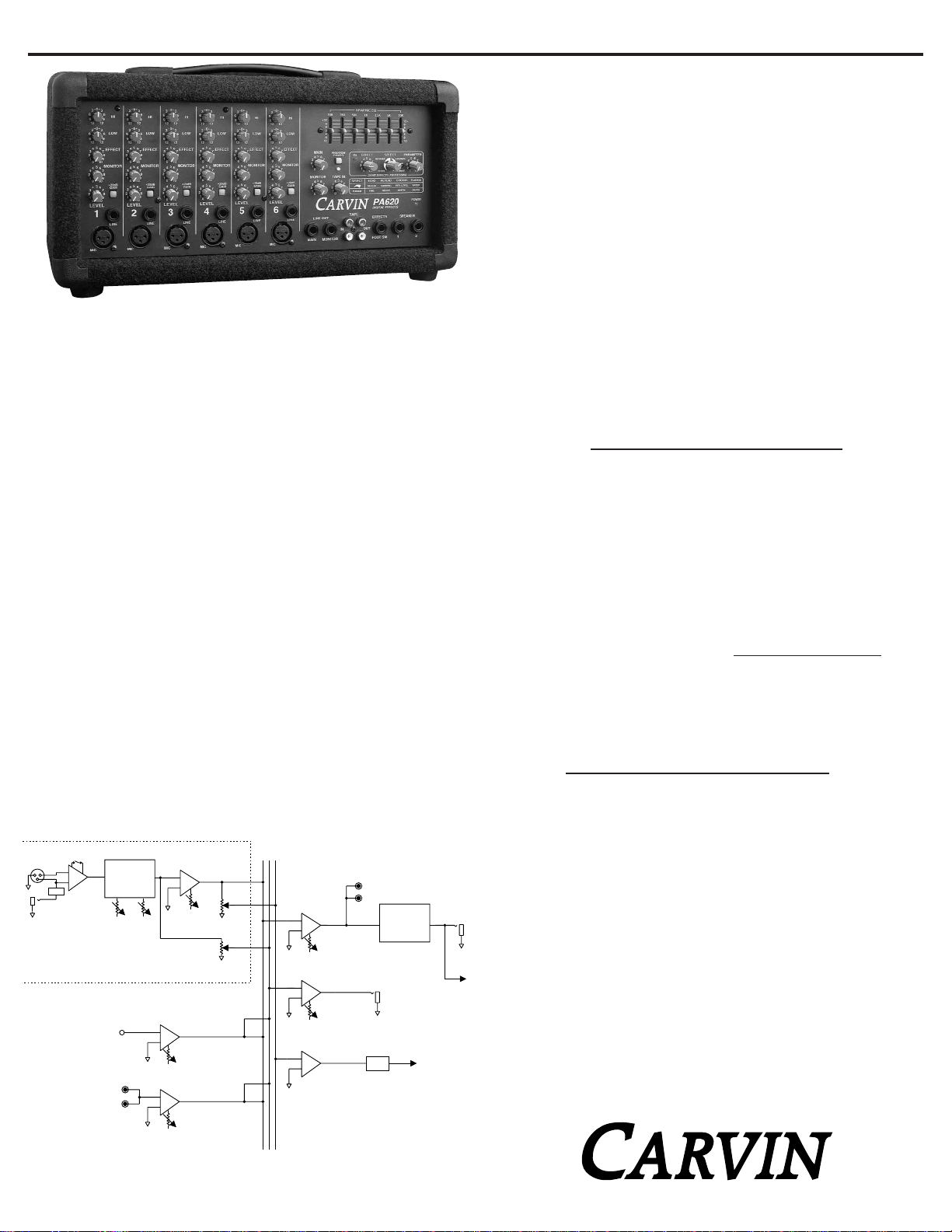
PA410 / PA620
BLOCK DIAGRAM
CARVIN ENGINEERING DATA
OPERATING MANUAL
PA410/PA620 POWERED MIXERS
20dB
GAIN SWITCH
MIC
PRE
PAD
line pad
(-26dB)
CHANNEL
TAPE INPUT
TWO BAND
CHANNEL TONE
CONTROLS
HI LOW
RETURN FOR
INTERNAL DSP
CHANNEL
LEVEL
CHANNEL
MONITOR
LEVEL
DSP RETURN
LEVEL
TAPE INPUT
LEVEL
CHANNEL
EFF SND
DSP TO
MONITOR
TAPE TO
MONITOR
MAIN
MON
EFF
TAPE OUT
SEVEN BAND
GRAPHIC
EQUALIZER
MAIN
SUMMING AMP
AND LEVEL
MONITOR
LINE OUT
MONITOR
SUMMING AMP
AND LEVEL
GAIN
REDUCTION
FOR DSP
INTERNAL
EFFECTS
SUMMING AMP
DSP SEND
MAIN
LINE OUT
TO INTERNAL
POWER AMP
Page 3
LIVE SOUND SYSTEM
In a live sound reinforcement or a public address system (P.A.
System), the input signals to the mixer will come from the microphones and instruments on the stage. Each microphone or instrument to be amplified by the P.A. system must be connected to one
of the mixer’s inputs. If you have enough channels, try to mic each
stage instrument. This allows for the best overall sound control of
the instruments as they are mixed together and then amplified by
the P.A. system. This will also provide the ability to record your
performace with all instruments in the mix via the TAPE OUT RCA
jacks.
THE SOUND CHECK
The sound check takes some skill, but mostly patience from the
performers and especially you the system operator. If you get frustrated during the sound check the performers can lose confidence
and the sound may suffer due to things missed in the sound check.
The basic sound check follows this format: First test all micro-
phones and other input devices (direct boxes, etc.) before the performers are included in the sound check. A good thing to also
check here is feedback in the monitors from the microphones.
Good positioning of the monitors and the use of the graphic equalizer solves most major monitor feedback problems. Now for a
sound check with the performers. First set the level of each performer individually and in cases where a performer has multiple
microphones, such as with a drummer, set each drum mic individually then the drum set as a whole. This is also a good time to
make some channel tone control adjustments to tailor the sound of
the individual performers and instruments. Next after setting each
individual, have the performers run through a song or a portion of
the show. Don’t hesitate to stop the performers if something needs
to be adjusted or if an individual performer or microphone needs to
be heard solo again. Remember the sound check is not a rehearsal, but a system check, a time to work the bugs out of the system
so the show can go smoothly.
0
1
2
3
456
7
8
9
10
0
1
2
3
4
5
6
7
8
9
10 0
1
2
3
4
5
6
7
8
9
10
MONITOR TAPE IN
MAIN
PHANTOM
FOOT SW
PA620
PK
0
1
2
3
456
7
8
9
10
PARAMETER
110
2
3
4567
8
9
SELECTEFFECT
LINE OUT
1
SPEAKER
2
EFFECTS
MONITORMAIN
POWER
OUT
TAPE
IN
DIGITAL EFFECTS
24-BIT EFFECTS PROCESSING
FLANGE
REVERB
ECHO
CHORUS
PARAM
ECHO
REGEN
TIME
REVERB
DAMPING
DECAY
FLANGE
SPEED
DEPTH
CHORUS
REV LEVEL
DEPTH
SELECT
TWO-TRACK
RECORDER
R/L
TAPE
OUT
R/L
TAPE
IN
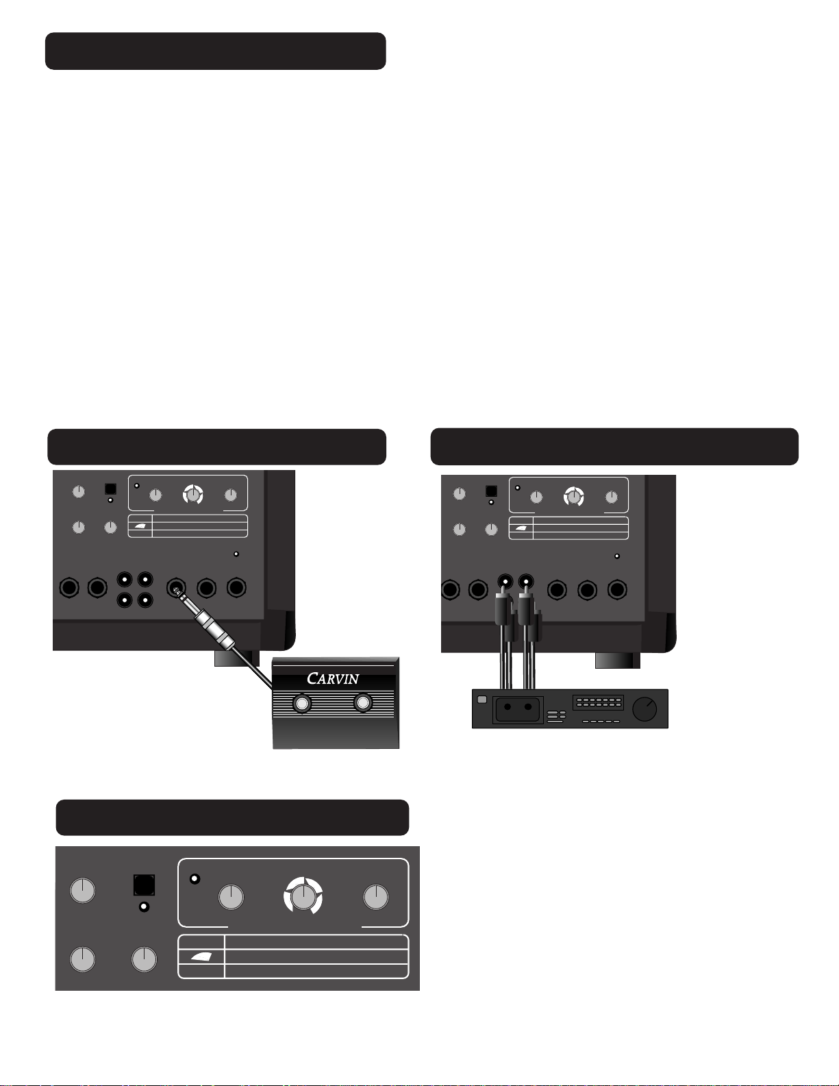
TAPE AND CD IN - OUT
DSP EFFECTS FOOTSWITCH
The hook up is simple,
using four (or two
stereo) RCA cables.
Plug the TAPE OUT on
the mixer into the tape
deck’s inputs and the
mixer’s TAPE RTN’s
into the tape deck’s
outputs. This can provide the means to
record a performance
or play pre-recorded
music through the
mixer.
DSP EFFECTS SELECTOR
Use Carvin’s FS22 footswitch to remotely turn effects on and off.
The PA410 and PA620 effects offer a wide
array of effect possibilities. Use the SELECT
control to dail in your desired effect. Use the
PARAMETER control to change characteristics
about that effect. For a detailed description of
each EFFECT and PARAMETER please see
11. DSP EFFECTS SELECTOR
.
FS22
MAIN
PHANTOM
PK
POWER
456
3
7
2
8
9
1
10
0
MONITOR TAPE IN
5
5
6
4
4
7
3
3
2
8
2
1
9
1
0
10 0
LINE OUT
MONITORMAIN
6
7
8
9
10
TAPE
IN
456
3
2
1
0
10
24-BIT EFFECTS PROCESSING
ECHO
SELECT
REGEN
PARAM
TIME
OUT
REVERB
7
8
9
PA620
DIGITAL EFFECTS
EFFECTS
FOOT SW
ECHO
REVERB
DAMPING
DECAY
PARAMETER
SELECTEFFECT
CHORUS
4567
3
8
2
9
110
FLANGE
FLANGE
CHORUS
SPEED
REV LEVEL
DEPTH
DEPTH
SPEAKER
1
2
MAIN
456
3
2
1
0
MONITOR TAPE IN
5
4
3
2
1
0
PHANTOM
POWER
7
8
9
10
6
7
8
9
10 0
5
4
3
2
1
6
10
7
8
9
SELECT
PK
PARAM
SELECTEFFECT
REVERB
456
7
3
2
8
1
9
0
10
ECHO
24-BIT EFFECTS PROCESSING
ECHO
REVERB
REGEN
DAMPING
TIME
DECAY
PARAMETER
CHORUS
FLANGE
CHORUS
REV LEVEL
DEPTH
4567
3
2
110
FLANGE
SPEED
DEPTH
8
9
Page 4

MIC CHANNEL FEATURES
1. XLR MICROPHONE INPUT
The XLR MIC input is designed for balanced low impedance
(microphone) input signals. The differential balanced input
amplifier reduces the common noise picked up on the
microphone cables. The XLR connector is wired as per the
industry standard, pin 1 is ground, pin 2 is non-inverting
(positive), and pin 3 is inverting (negative). Phantom power
is available on every XLR input jack when the phantom
power switch in the master section is pressed. This feature
allows condenser microphones to be run directly from the
mixer. Note: When using phantom power, make sure the
phantom power is switched off before connecting or disconnecting microphones to the mixer. It is recommended
to allow 5 seconds for the phantom power to discharge
before making any microphone connections. Also, to avoid
hearing a pop, turn down the master volume when turning
on the phantom power.
2. LINE INPUT JACK
The LINE input is a 1/4” phone jack designed for unbalanced
line and instrument level inputs. Examples to use in these
inputs are guitars, keyboards, mics, or a CD or tape player.
The line inputs can be used at the same time the XLR inputs.
3. +20DB GAIN SWITCH
The GAIN switch increases the input sensitivity on both the
LINE and MIC input jacks by 20dB. After determining the
input is too low for mixing with the level control, turn down
the level control, press in the gain switch and adjust the
level again. If distortion is heard regardless of the channel
LEVEL control’s setting, disengage this switch to eliminate
over-driving of the input stage.
4. CHANNEL LEVEL CONTROL
The LEVEL control adjusts the volume of the channel before
going to the MAIN master LEVEL. Here is where the individual channel volumes are adjusted to make up the desired
mix heard at the main outputs. A general rule to prevent
interstage distortion is to always keep the MAIN master
LEVEL the same or higher than the channel LEVEL.
5. MONITOR LEVEL CONTROL
The MONITOR level control adjusts the volume of the channel going to the monitor mix. The monitor level control is
pre-channel level and pre-channel tone controls. This
means it is unaffected by adjustments in channel level and
tone controls. The purpose for this is so the main mix
adjustments for tone and level can be made without disturbing the monitor mix.
6. CHANNEL EFFECTS LEVEL CONTROL
The EFFECT control adjusts the volume of the channel going
to the internal effects. Make sure the effects level is not set
too high, if the master effect PK (Peak) LED flashes red, turn
down the Channel Effect until it stops flashing. See # 11 for
more details.
7. CHANNEL TONE CONTROLS
Each channel features active tone controls LOW and HI. Both
function as boost (clockwise) & cut (counter-clockwise) controls where the center 0 position is neutral. Both LOW and HI
are shelving type tone controls with corner frequencies at
80Hz and 11.5k Hz respectively. It is suggested the channel
tone controls start out in their center 0 positions. A good setting for added dynamics is to set the LOW & HI at +6.
8. THE GRAPHIC EQUALIZER
The 7 band graphic EQ is an excellent tool to fine tune the
overall mix. Set all sliders to their center detent position.
When the sliders are in this position, they do not effect the
audio signal. When a slider is raised or lowered it boosts and
cuts the listed frequency respectively. One setting that can be
used to enhance your sound is to cut the mid range (set the
1KHz slider to -8) and raise the high and low frequencies as
shown. This is a common “smile” curve that gives a tight
punchy sound with
plenty of highs to
cut through a
crowd. The
Graphic EQ can
also help to reduce
feedback.
9. MAIN MASTER LEVEL CONTROL
The MAIN control is the master volume control for the mixer. The
MAIN will control the volume of the LINE OUT jack, the TAPE OUT
RCA jack and the internal power amplifier (speaker volume).
10. PHANTOM POWER
SWITCH AND LED
The PHANTOM power switch turns on the microphone
phantom power in the channel XLR jacks. This power is
used for supplying a bias voltage to condenser microphones. The LED indicates the phantom power is turned
on. The phantom power will not damage dynamic microphones.
PA410 / PA620 CONTROLS
1
PA620
4
5
6
7
3
2
QUICK START UP
If you’re like most new owners, you’re probably in a
hurry to plug your mixer in and use it. Here are some
brief instructions to get you going quickly. With the
mixer unplugged and the unit turned off, complete the
following procedures:
1. CONNECTING AC POWER TO YOUR MIXER
• Be sure to use the correct power cable for your country.
(120VAC or 240 VAC)
• Use only a grounded (3 prong) power outlet to prevent
a shock hazard and reduce hum and noise.
2. CONNECTING SPEAKERS
• Use the 1/4” SPEAKER jacks on the front panel to connect up to two 8Ω speakers. The speaker cables are to
be non-shielded with a minimum size of 16 gauge.
NOTE: Do not run your speakers through microphone
wire, guitar cables, or multi-conductor microphone
junction boxes or “snakes” as they are sometimes
referred to. This wire is normally shielded and of a very
light gauge causing a substantial loss of power.
3. CONNECTING INPUTS TO YOUR MIXER
• For low level balanced devices such as microphones, plug
into the balanced MIC inputs using a shielded XLR cable.
• For high level unbalanced devices such as instruments
& Keyboards plug into the LINE input jacks using a
shielded 1/4” phone cable. Set the GAIN switch so the
LEVEL control is not overly sensitive.
4. TURNING YOUR MIXER ON
• Turn all channel and master LEVEL controls to their off
positions
• Adjust all “EQ” tone controls— the channel’s HI and LOW
and the 7 Band Graphic EQ’s to their center position.
• Turn the mixer on by the rear panel POWER SWITCH and
watch for the POWER LED to light. Your mixer is now
ready to operate.
MASTER SECTION FEATURES
GRAPHIC EQ
250 500100
+
12
8
4
0
4
8
12
-
1K 2.5K
5K 10K
+
12
8
4
0
4
8
12
-
Page 5

11. DSP EFFECTS SELECTOR
The 24bit processor will provide a host of awesome sounding effects that include: Flange, Reverb, Echo, & Chorus. The
EFFECT control will adjust the volume level of the selected
effect. Remember each channel has its own EFFECT send
that will adjust the amount of signal sent to the effects
processor. The red PK LED will indicate when the effects signal from the channel is clipping. Lowering the channel
EFFECT control until the PK LED stops flashing is a good rule
of thumb when setting up your effects. (Note: An audible
note can be heard when adjusting the effects).
EFFECT PARAMETERS
Each of the four effects has a variable parameter that can be
easily adjusted.
ECHO: When the SELECT control is at the “7 O-clock” posi-
tion, it is selected to the first ECHO setting where you get a
single repeat echo (minimal regeneration). Turning the
PARAMETER control to 1 will provide the shortest delay time
between the original signal and the echo. Increasing the
PARAMETER
control to the
right will
increase the
time delay
between the
original signal
and the echo.
You can get a maximum of .5 second delay. To increase the
number of echoes, turn the SELECT control clockwise to “9
O-clock” (maximum regeneration).
REVERB: When the SELECT control is at the “10 O-clock”
position, it is selected to the first REVERB setting. Turning
the SELECT control clockwise will increase the amount of
high frequencies in the reverb. Turning the PARAMETER con-
trol to 1 will provide minimal decay time of the reverb.
Increasing the PARAMETER to the right will increase the
reverb decay time.
CHORUS: When the SELECT control is at the “1 O-clock”
position it is selected to the first CHORUS setting. Turning
the SELECT control clockwise will increase the amount
reverb in the chorus. Turning the PARAMETER control to 1
will provide a minimal chorus depth setting. Increasing the
PARAMETER to the right will increase the chorus depth.
FLANGE: When the SELECT control is at the “4 O-clock”
position it is selected to the first FLANGE setting. Turning the
SELECT control clockwise will increase the flanger’s speed.
Turning the PARAMETER control to 1 will provide minimal
flanging depth. Increasing the PARAMETER to the right will
increase the flanger’s depth.
12. MONITOR MASTER LEVEL CONTROL
The MONITOR master level control is the master volume
for the monitor mix which is sent to the monitor output.
This control receives its signals from the channel monitor
level controls.
13. TAPE IN
The TAPE IN control sets the level coming from the RCA
TAPE IN jacks. Just like the channel LEVEL control, the
TAPE IN will add this signal to your overall mix with your
MAIN control adjusting the entire mixer volume output.
14. MONITOR OUTPUT JACK
The MONITOR line out jack is the monitor mix from the
MONITOR master level control. This is a line level output to
drive an external power amplifier like our HT100M for separate floor monitors. This output will include any effects
mixed at the individual channels allowing you to hear your
effects in your monitors!
15. MAIN OUTPUT JACK
The MAIN line out jack is a line level post graphic EQ output
of the main mix. Use this to drive an external power amp.
This same signal is also being fed to the internal power
amplifier.
16. TAPE IN-OUT RCA JACKS
The RCA IN jacks are Ideal for pluggng in keyboard, cassette deck or CD player. The LEFT/RIGHT TAPE OUT RCA
jacks deliver the main mix for recording (pre graphic EQ).
17. EFFECTS/FOOTSWITCH
Plug the optional FS22 footswitch into this jack to remotely turn the effects ON or OFF.
18. SPEAKER OUTPUT JACKS
Connect the main speakers to these two 1/4” phone jacks.
A total of two 8Ω speakers can be connected (one per
jack). Connecting 4Ω speakers or more than two 8Ω
speakers will cause the mixer to go into “protect mode”
and mute the audio. The output relay will engage after 20
minutes of heavy use when using 4Ω speakers.
19. POWER LED
The Power LED indicates when the mixer is powered up.
HELPFUL HINTS
1) FEEDBACK: To reduce feedback, the placement of the
speakers with respect to the microphones may need to be
reconsidered. As much as possible, try to have the main
speaker facing away from and in front of the microphones
not on stage behind them. The graphic EQ may be used to
reduce feedback from microphones.
2) NO HIGH FREQUENCIES: Check the channel tone controls and EQ settings. The tweeters or midrange drivers may
have been damaged or blown from feedback or overpowering.
1612
9
12
14
17
18
13
15
11
19
8
10
Page 6

SYSTEM WITH MONITORS
8Ω
8Ω
Min. impedance: 8Ω per speaker
-
+
08448
12
12
12+
GRAPHIC EQ
100 250 500 1K 2.5K 5K 10K
+12
08448
08448
8
9
7
SPEED
DEPTH
FLANGE
56
110
4
2
3
12-
PARAMETER
CHORUS
SELECTEFFECT
REVERB
7
6
5
4
PK
POWER
PHANTOM
789
±12
6
5
4
MAIN
DEPTH
CHORUS
FLANGE
REV LEVEL
DECAY
DAMPING
REVERB
ECHO
8
9
10
24-BIT EFFECTS PROCESSING
0
123
10
0
123
ECHO
SELECT
6
5
6
5
MONITOR TAPE IN
PA620
DIGITAL EFFECTS
TIME
REGEN
PARAM
789
10
4
123
789
10 0
0
4
123
SPEAKER
EFFECTS
TAPE
LINE OUT
2
1
FOOT SW
OUT
IN
MONITORMAIN
5K 10K 10K 10K
CHANNEL 1
1K 2.5K
dcm
250 500100
08448
12
12
+
-
345
2
6
1
7
8
0 dB
9
10
11
CHANNEL
12
13
50
15
30
171922
345
2
6
1
7
8
0 dB
9
12
10
11
CHANNEL
12
13
50
15
30
17
22
19
-
+
08448
12
12
5K 10K 10K 10K
CHANNEL 1
1K 2.5K
250 500100
08448
12
12
+
-
HI
6
3
0
3
6
HI
6
3
0
3
6
HI
6
3
0
3
6
HI
6
3
0
3
6
HI
6
3
0
3
6
HI
6
3
0
3
6
LOW
6
3
12
0
3
12
99
6
LOW
6
3
12
0
3
12
99
6
LOW
6
3
12
0
3
12
99
6
LOW
6
3
12
0
3
12
99
6
LOW
6
3
12
0
3
12
99
6
LOW
6
3
12
0
3
12
99
6
EFFECT
12
6
5
4
12
321
99
EFFECT
12
6
5
4
12
321
99
EFFECT
12
6
5
4
12
99
321
EFFECT
12
6
5
4
12
321
99
EFFECT
12
6
5
4
12
321
99
EFFECT
12
6
5
4
12
321
99
20dB
GAIN
MONITOR
987
987
987
6
6
5
5
4
321
321
321
321
321
321
010
010
321
20dB
GAIN
987
987
6
5
4
010
010
321
20dB
GAIN
987
987
6
5
4
010
010
LEVEL LEVEL LEVEL
321
20dB
GAIN
987
987
6
5
4
010
010
321
20dB
GAIN
987
987
6
5
4
010
010
321
20dB
GAIN
987
987
6
5
4
010
010
LEVEL LEVEL LEVEL
321
4
010
MONITOR
987
6
5
4
010
MONITOR
987
6
5
4
010
MONITOR
987
6
5
4
010
MONITOR
987
6
5
4
010
MONITOR
987
6
5
4
010
LINE
654
MIC
LINE
MIC
LINE
4
MIC
LINE
3
MIC
LINE
2
MIC
LINE
1
MIC
 Loading...