

Page 1
F150
PROFESSIONAL STEREO POWER AMPLIFIER
OPERATION MANUAL
Manual No. 76-01528
Revision 1.1
Made in USA
12340 World Trade Drive
San Diego, CA 92128
(800)854-2235
HELPLINE
1-800-854-2235
12340 World Trade Drive
San Diego, CA 92128
Record the serial number of your amplifier in the space provided below:
Serial No._________________ Invoice Date________________
POWER
1
2
3
4
5
6
7
8
91011
12
13
15
17
19
22
30
50
0 dB
CH 1
1
2
3
4
5
6
7
8
91011
12
13
15
17
19
22
30
50
0 dB
CH 2
OUT
IN
O
F
F
O
N
EQ EXPAND
POWER
1
2
3
4
5
6
7
8
91011
12
13
15
17
19
22
30
50
0 dB
CH 1
1
2
3
4
5
6
7
8
91011
12
13
15
17
19
22
30
50
0 dB
CH 2
OUT
IN
O
F
F
O
N
EQ EXPAND
POWER
1
2
3
4
5
6
7
8
91011
12
13
15
17
19
22
30
50
0 dB
CH 1
1
2
3
4
5
6
7
8
91011
12
13
15
17
19
22
30
50
0 dB
CH 2
OUT
IN
O
F
F
O
N
EQ EXPAND
Page 2
WARRANTY AND SERVICE INFORMATION
Call Toll-Free 800-854-2235 if you need help with your CARVIN product. If you need to
return it for service, our service dept. will issue a Service Number so that we can expect
your shipment. Write the Service Number on the carton and be sure to include a full
description of every problem. Pack in its original carton using all its packing material.
Return by UPS pre-paid. Units returned with physical damage, missing parts, or damage
from improper service are not serviceable.
REPAIRS UNDER WARRANTY (1Year)
There is no charge for service under warranty. However, shipping is to be paid both
ways by the customer.
REPAIRS OUT OF WARRANTY
After your warranty has expired, call us for the current flat rate charge which includes
parts labor and testing to bring your unit up to factory specifications.
SERVICING IN YOUR AREA
You may select your own service center or have your own qualified technician work on
the unit at your own expense. This will not void the warranty unless damage was done
because of improper servicing. Under the ONE YEAR WARRANTY, Carvin will ship parts
pre-paid to you or your technician providing that the defective part(s) are first returned for
our inspection. If you do not have a qualified service person, we ask that you do not
involve yourself in servicing the unit.
LIMITED WARRANTY
Your Carvin Professional Series Product is guaranteed against failure for ONE YEAR.
Carvin will service the unit and supply all parts at no charge to the customer providing the
unit is under warranty. CARVIN DOES NOT PAY FOR PARTS OR SERVICING OTHER
THAN OUR OWN. This warranty is extended to the original purchaser only and is not
transferable. THIS WARRANTY DOES NOT INCLUDE FAILURES CAUSED BY INCORRECT USE, INADEQUATE CARE OF THE UNIT, OR NATURAL DISASTERS. A COPY
OF THE ORIGINAL INVOICE IS REQUIRED TO VERIFY YOUR WARRANTY. Carvin
takes no responsibility for any horn driver or speaker damaged by this unit. This warranty
is in lieu of all other warranties, expressed or implied. No representative or person is
authorized to represent or assume for Carvin any liability in connection with the sale or servicing of Carvin products. No liability is assumed for damage due to accident, abuse, lack
of reasonable care, loss of parts, or failure to follow Carvin’s directions. CARVIN SHALL
NOT BE LIABLE FOR INCIDENTAL OR CONSEQUENTIAL DAMAGES.
In the interest of creating new products and improving existing ones, Carvin is continually researching the
latest state of the art audio design methods, and modern packaging and production techniques. Thus,
Carvin reserves the right to make changes in its products and specifications without notice or obligation.
12340 World Trade Drive
San Diego, CA 92128
800-854-2235
ATTENTION:
RISQUE DE CHOC ELECTRIQUE - NE PAS OUVRIR
CAUTION
RISK OF ELECTRIC SHOCK
DO NOT OPEN
CAUTION: TO REDUCE THE RISK OF ELECTRIC SHOCK, DO NOT OPEN CHASSIS; DO NOT DEFEAT OR REMOVE THE
GROUND PIN OF THE POWER CORD; CONNECT ONLY TO A PROPERLY GROUNDED AC POWER OUTLET.
WARNING: TO REDUCE THE RISK OF FIRE OR ELECTRIC SHOCK DO NOT EXPOSE THIS EQUIPMENT TO RAIN OR MOISTURE.
CAUTION: NO USER-SERVICEABLE PARTS INSIDE. REFER SERVICING TO QUALIFIED SERVICE PERSONNEL.
U.K. MAINS PLUG WARNING: A moulded mains plug that has been cut off from the cord in unsafe.
Discard the mains plug at a suitable disposal facility. NEVER UNDER ANY CIRCUMSTANCES
SHOULD YOU INSERT A DAMAGED OR CUT MAINS PLUG INTO A 13 AMP POWER SOCKET.
Do not use the mains plug without the fuse cover in place. Replacement fuse covers can be obtained
from your local retailer. Replacement fuses are 13 amp and MUST be ASTA approved to BS1362.
EXPLANATION
OF SYMBOLS:
“IT IS NECESSARY FOR THE USER TO REFER TO THE INSTRUCTION MANUAL”
“REFERREZ-VOUS AU MANUAL D’UTILISATION”
“UNBEDINGT IN DER BEDIENUNGSANLEITUNG NACHSCHLAGEN”
“DANGEROUS VOLTAGE”
“DANGER HAUTE TENSION”
“GEFAHLICHE SPANNUNG”
IMPORTANT! FOR YOUR PROTECTION, PLEASE READ THE FOLLOWING:
WATER AND MOISTURE: Appliance should not be used near water (e.g. near a bathtub, washbowl,
kitchen sink, laundry tub, in a wet basement, or near a swimming pool, etc). Care should be taken so
that objects do not fall and liquids are not spilled into the enclosure through openings.
POWER SOURCES: The appliance should be connected to a power supply only of the type described
in the operating instructions or as marked on the appliance.
GROUNDING OR POLARIZATION: Precautions should be taken so that the grounding or polarization
means of an appliance is not defeated.
POWER CORD PROTECTION: Power supply cords should be routed so that they are not likely to be
walked on or pinched by items placed upon or against them, paying particular attention to cords at
plugs, convenience receptacles, and the point where they exit from the appliance.
SERVICING: The user should not attempt to service the appliance beyond that described in the operating instructions. All other servicing should be referred to qualified service personnel.
FUSING: If your unit is equipped with a fuse receptacle, replace only with the same type fuse. Refer
to replacement text on the unit for correct fuse type.
SAFETY INSTRUCTIONS (EUROPEAN)
NOTICE FOR CUSTOMERS IF YOUR UNIT IS EQUIPPED WITH A POWER CORD.
WARNING: THIS APPLIANCE MUST BE EARTHED.
The cores in the mains lead are coloured in accordance with the following code.
GREEN and YELLOW - Earth BLUE - Neutral BROWN - Live
The power cord is terminated in a CEE7/7 plug (Continental Europe). The green / yellow
wire is connected directly to the unit’s chassis. If you need to change the plug, and if you
are qualified to do so, refer to the table below.
WARNING: If the ground is defeated, certain fault conditions in the unit or in the sys-
tem to which it is connected can result in full line voltage between chassis and earth
ground. Severe injury or death can then result if the chassis and the earth ground are
touched simultaneously.
CONDUCTOR
WIRE COLOR
NORMAL ALTERNATIVE
LIVEL BROWN BLACK
NEUTRALN BLUE WHITE
EARTHE GREEN / YEL GREEN
Page 3
1
12
There are several differences between the two but of primary concern are power cord and
fuse values. Models with power cords containing the standard North American three prong
plug are for use with 120VAC where models with the European CEE-7 plugs are for 230V.
The following chart shows what fuse values to use for each model:
FUSE SELECTION
There are two versions of the F150 amplifier. A 120 Volt AC version for those countries
supplying 120 and a 230 Volt version for others.
Fuse Selector Chart
Mains Fuse Value Size Carvin P/N
120 VAC . . . .2A, 250V, Slow Blow ............3AG, 1/4 x 1 1/2”...........70-22020
230 VAC . . . .1A, 250V, Slow Blow ............3AG, 1/4 x 1 1/2”...........70-22010
Warning: Installing a wrong value fuse can damage the amplifier or create a fire haz
ard.
F150 SPECIFICA TIONS
MAINTENANCE
Carvin’s F150 amplifiers have passive free-flow ventilation and require no filter maintenance. However, use caution to avoid spilling liquids or allowing any other foreign matter
inside the unit. As with all pro-audio gear, avoid prolonged use in caustic environments
(i.e., on the beach). When used in such an environment, please be sure the amplifier is
adequately protected by rack, covers, etc..
To clean the unit, always use a mild detergent and warm water solution applied to a soft
cloth. Never spray cleaning products directly on the unit.
Output Power
8Ω, 1kHz, < 1% THD 150 Watts
(BRIDGE MONO)
8Ω, 1kHz, < 0.5% THD 60/60 Watts
4Ω, 1kHz, < 0.5% THD 75/75 Watts
(Stereo, both channels driven)
THD
20-20kHz < 0.1%
(8Ω at half power)
Damping Factor >400
Sensitivity (@ 4Ω)1.0 Vrms
Signal to Noise Ratio
85 dB
Weight (Shipping) 11lbs.
Power Consumption
(120V)
200 VA
(240V)
200 VA
Frequency Response
±0.5 dB, 20 Hz to 20 kHz
Input Impedance > 20kΩ Balanced or Unbalanced
Dimensions 1 3/4” High x 19” Wide x 10” Deep
Professionals know that for years Carvin has provided the industry with the best value
possible. And this amplifier is a great example of that value.
With 75 Watts RMS per channel of continuous output power this amplifier will fit many
applications. Its flat output response and crystal clear sound make it well suited for studio
reference, home theatre, stage monitor, bi-amp or a headphone amplification just to name
a few. With the EQ Expand feature you can add just a touch of flavor for Guitar, Bass or
Keyboard rigs.
State of the art design makes this amp ruggedly reliable by integrating rock solid protection circuitry. It endures shorted speaker cables, power line surges, open outputs and
other conditions known to harm amplifiers. This kind of reliability will ensure many years of
listening enjoyment.
Considering its high quality performance, user friendly features, professional input/output
connectors, integrated design and low cost, you can rest assured that buying this World
Class Carvin product was the best possible decision.
INSPECT YOUR AMPLIFIER FOR ANY DAMAGE which may have occurred during shipment. If any damage is found, notify the shipping company and call CARVIN immediately.
SAVE THE CARTON & ALL PACKING MATERIALS. In the event you have to reship this
amplifier, always use the original carton and packing material. This will provide the best
possible protection during shipment. Neither CARVIN nor the shipping company are liable
for damage caused by improper packing.
SAVE YOUR INVOICE. It will be required for warranty service. Immediately check your
invoice against the items received.
SHIPMENT SHORTAGE. If items are missing, it may be that they were shipped separately. Please allow several days for the balance of your order to arrive before inquiring. If
you determine (after allowing an appropriate amount of time) you have not received all the
items you ordered, please call CARVIN.
Carvin’s USA toll free number: 800-854-2235
RECEIVING INSPECTION
CONGRA TULATIONS!
You made a wise decision in buying a Carvin F150 amplifier. Not only did you get a refer-
ence quality amplifier but also one with the clarity and power professionals require.
QUICK SET UP
Like most new owners, you’re probably in a hurry to plug in your F150 and audition it.
Here are some brief instructions to get you going quickly.
CONNECTING AC POWER
Use only a grounded (3 prong) power outlet to avoid shock hazard.
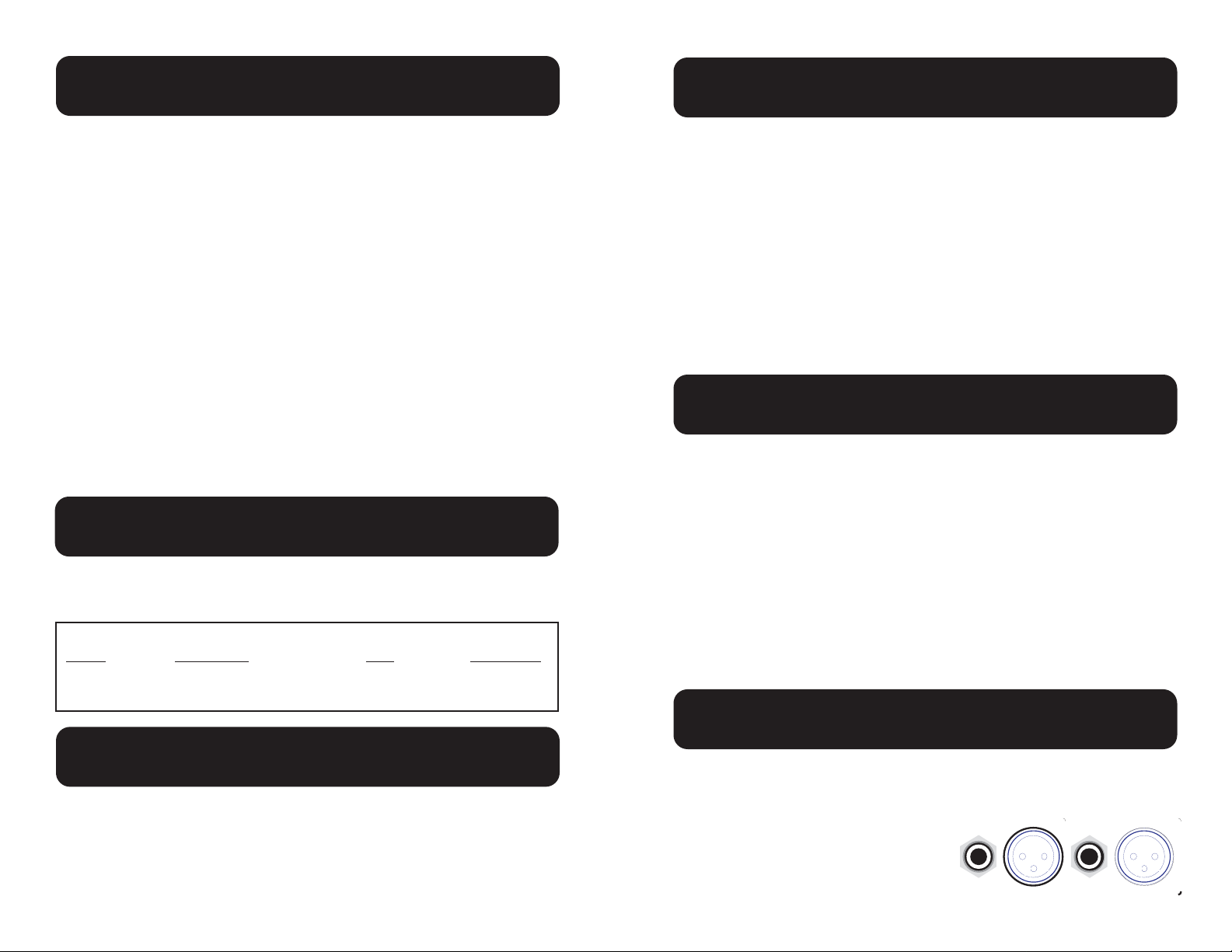
INPUT CONNECTIONS
Balanced XLR and 1/4” phone input connectors are located on the rear panel and labeled
“INPUT1 & INPUT2”. The 1/4” phone jacks
can be used with either balanced (ring-, tip+,
sleeve gnd) or unbalanced (tip, sleeve) plugs.
2 1
3
2 1
3
INPUT 1
INPUT 2
BALANCED LINE
BRIDGE INPUT
Page 4

CONNECTING SPEAKERS:
STEREO MODE
Along with standard 1/4” phone jacks there
are binding posts located within a box on the
rear panel labeled “SPEAKERS”.
BRIDGE MONO MODE
This power amplifier can be converted
from stereo to mono, providing twice the
power capacity of a single channel, by
switching into BRIDGE MONO mode and
connecting the speakers to the two RED
binding posts.
When the rear panel switch labeled BRIDGE is set to its ‘out’ position, the amplifier is con-
figured for normal STEREO operation.
When the rear panel switch labeled BRIDGE is set to its ‘in’ position, the amplifier is setup
for BRIDGE MONO operation. This causes channel 2’s outputs to be “out of phase” from
channel 1’s. In this configuration a single set of speakers is connected with one lead going to
channel 1’s RED binding post and the other lead going to channel 2’s RED binding post.
(See the “Typical Bridge Mono Triamp” illustration on page 6.)
When ‘bridging’ an amp, the impedance capacity is always reduced in half. For example;
since the F150’s outputs are rated for a minimum of 4Ω per channel, the lowest impedance
allowed in bridge mode is 8Ω. (Note: Operating the amplifier with loads below the rated
minimum will cause premature distortion.)
EQ EXPAND SWITCH
This switch, when set to its ‘in’ position will boost the highs and lows by +4dB at 80Hz and
12kHz. This works well as a loudness contour when operating at low volume levels or adds
flavor when using it in a bass or guitar rack. When set to the ‘out’ position it provides a flat
output response. Try it both ways and set as desired.
1 2
–
MONO
BRIDGE
SPEAKERS
8 OHMS
MIN.
STEREO
MONO
1 2
–
MONO
BRIDGE
BRIDGE SPEAKERS
8 OHMS
MIN.
POWER
1
2
3
4
5
6
7
8
91011
12
13
15
17
19
22
30
50
0 dB
CH 1
1
2
3
4
5
6
7
8
91011
12
13
15
17
19
22
30
50
0 dB
CH 2
OUT
IN
O
F
F
O
N
EQ EXPAND
POWER-UP SEQUENCE
Follow these simple steps when applying power to the system.
1. Verify all system connections while power is still off.
2. Lower all power amplifier level controls to minimum.
3. Apply power to the mixers, processors etc. first.
4. Apply power to the power amplifiers last.
5. Setup mixer, processors etc. to nominal operating levels.
6. Set power amplifier level controls to desired volume.
Note: Reverse this procedure for power-down.
11
One or both clip LED’s
flash intermittently
cont’d
Sound is distorted and
clip indicator(s) are on
Sound is distorted and
clip indicator(s) are not
on or only flash occasionally
One or both channels
distort or cut out every
few minutes
Sound is coming from
both channels when only
one channel has signal
at its input
Shorted speaker or speaker cable
Too many speakers
Amplifier input signal is too
high
Unit entering PROTECT
mode due to overheating
Rear panel “BRIDGE”
switch is in the mono position
the sound is not distorted.
Running the system with
the LED’s continuously lit
will not harm the power
amp but is dangerous to
speakers whose power
ratings are not well above
the amplifier’s power rating.
Try different cables and
speakers
Try connecting one speaker system at a time.
Turn down the output level
of equipment feeding the
amplifier. If the sound
level is too low then raise
the controls on the front of
the power amp.
Make sure both the front
and rear of the amplifier
has adequate space for
ventilation.
Verify that the total speaker load is not less than 4Ω
(i.e., three 8Ω speakers
per channel is less than
4Ω total.)
Check for shorted speaker
cables.
Move “BRIDGE MONO”
switch to the Stereo position.
CorrectionProblem Possible Cause
TECHNICAL ASSISTANCE
If the above chart has not been able to guide you to the problem then answer the follow-
ing five questions:
1. AC cord attached to a source ‘alive’ with appropriate Voltage and current capacity?
2. Is the fuse OK and power switched on?
3. Correct level audio signal connected to inputs through known good cables?
4. Are the switches set properly and level controls raised sufficiently?
5. Are known good speakers connected properly using known good cables?
Carvin’s friendly technical support staff will be happy to assist by calling 800-854-2235.
2
Page 5

310
Power switch is on but
LED doesn’t light
The unit has power but
no output is present at
the speakers
Loud hum coming from
speakers
No sound out of one
channel
One or both clip LED’s
flash intermittently
Power plug is loose or disconnected
Circuit breaker tripped or
fuse blown in circuit fuse
box
Amplifier fuse blown
No input signal
Open speaker cable
Blown speaker fuse
Ground loop
Missing ground feed
(unbalanced only)
Bridge switch not set properly
Input signal
Reconnect plug.
Disconnect all other loads
on the same circuit and
reset circuit breaker or
replace fuse.
Disconnect the power cord
and replace fuse only with
same type and value
Check that the source
equipment is properly
feeding the amplifier’s
input. The green signal
LED’s will show if signal is
present.
Replace speaker cable
with a known good one.
Check speaker cabinet for
fuses and replace as necessary
Try lifting the shield
grounds from the input
cables (balanced inputs
only).
(Note: Never defeat the
ground prong of the AC
power cord. Serious
shock or electrocution
may occur.)
Replace input cables with
known good ones.
Make sure the bridge
switch is set to the appropriate position.
Clip LED’s light to indicate
maximum output level.
This is not a problem as
long as the LED’s don’t
stay continuously lit and
CorrectionProblem Possible Cause
IN CASE OF TROUBLE
Every F150 amplifier undergoes severe environmental “burn-in” as well as thorough com-
puter controlled and human testing. It is unlikely a malfunction will occur. However, when
something doesn’t seem to work properly, please refer to the following chart:
The following diagram illustrates the typical stereo setup. Although it shows XLR’s for
inputs and 1/4” phone plugs for outputs, a variety of alternative connectors are available
(see the following sections on “INPUT CONNECTIONS” and “OUTPUT CONNECTIONS”).
INPUT CONNECTIONS
The preferred method of connecting input signals is with balanced XLR’s (two conductors
plus a shield wire, such as Carvin’s XLR8). Balanced input signals provide the highest gain
and best noise rejection. 1/4” phone jacks are also capable of providing balanced input by
using a stereo plug (ring-, tip+ & sleeve gnd). However, not all sources provide balanced
outputs. In these cases an unbalanced 1/4” input is recommended (single conductor plus a
shield wire, such as Carvin’s SH2 or SH15).
MON 1 EFF 1 EFF 2
BAL SENDS
LEFT/3 RIGHT/4 MAIN
R
POWER
L
SENDS
C
CNTRL
STEREO RETURNS
TAPE SEND
L R
B
A
MON 2
RM
LAMP
12V
SUB 1 PHONESSUB 2
Left Speaker Right Speaker
Left
Speaker
Connector
Right Speaker
Connector
Left Input
Connector
Right Input
Connector
Mixer Output
Two conductors plus shield for
balanced input or one conductor
plus shield for unbalanced input.
Two conductor non-shielded, 16AWG
or larger, cable for speaker connections.
FUSE
2 132 1
3
120VAC 60Hz 200 VA
FUSE = 2 A SLOW BLOW
WARNING – REPLACE FUSE ONLY
WITH SAME TYPE AND VALUE.
WARNING – TO PREVENT FIRE OR SHOCK, DO NOT EXPOSE TO RAIN OR MOISTURE.
WARNING – DO NOT REMOVE COVER. NO USER SERVICEABLE PARTS INSIDE.
CAUTION – TO PREVENT SHOCK DO NOT DEFEAT THE SAFETY GROUND.
WARNING – TO PREVENT A FIRE HAZARD, PROVIDE ADEQUATE VENTILATION !
75 75 WATTS
4 OHMS MIN. PER CH.
STEREO
MONO
1 2
–
INPUT 1
MONO
BRIDGE
BRIDGE SPEAKERSINPUT 2
BALANCED LINE
MADE
AUS
INTHE
8 OHMS
MIN.
BRIDGE INPUTLOWER LOADS MAY RESULT
IN PREMATURE DISTORTION !
Typical Stereo Setup
CONNECTING THE SYSTEM
F150
Page 6

9
Parts List For F150 PCB Sub Assemblies
REF DESCRIPTION PART #
A1 Op-amp, Low noise . . . . . . . . . . . . . .60-45580
A2 Op-amp, Low noise . . . . . . . . . . . . . .60-45580
C1 Capacitor, Electrolytic, 4700µF, 50V .42-47251
C2 Capacitor, Electrolytic, 4700µF, 50V .42-47251
C3 Capacitor, Electrolytic, 470µF, 25V . .47-47125
C4 Capacitor, Electrolytic, 470µF, 25V . .47-47125
C5 Capacitor, Electrolytic, 10µF, 50V . . .47-10051
C6 Capacitor, Electrolytic, 10µF, 50V . . .47-10051
C7 Capacitor, Electrolytic, 10µF, 50V . . .47-10051
C8 Capacitor, Mylar, .047µF, 250V . . . . .41-47322
C100 Capacitor, Ceramic, 56pF . . . . . . . . .45-56052
C101 Capacitor, Ceramic, 56pF . . . . . . . . .45-56052
C102 Capacitor, Electrolytic, 10µF, 50V . . .47-10051
C103 Capacitor, Electrolytic, 10µF, 50V . . .47-10051
C104 Capacitor, Ceramic, 120pF . . . . . . . .45-12152
C105 Capacitor, Ceramic, 120pF . . . . . . . .45-12152
C106 Capacitor, Electrolytic, 10µF, 50V . . .47-10051
C107 Capacitor, Poly, .0047µF, 100V . . . .46-47212
C108 Capacitor, Poly, .022µF, 100V . . . . .46-22312
C109 Capacitor, Electrolytic, 10µF, 50V . . .47-10051
C110 Capacitor, Poly, .1 µF, 100V . . . . . . .46-10412
C111 Capacitor, Poly, .1 µF, 100V . . . . . . .46-10412
C112 Capacitor, Electrolytic, 10µF, 50V . . .47-10051
C113 Capacitor, Electrolytic, 10µF, 50V . . .47-10051
C114 Capacitor, Mylar, 0.22µF . . . . . . . . . .46-22412
C115 Capacitor, Electrolytic, 10µF, 50V . . .47-10051
C200 Capacitor, Ceramic, 56pF . . . . . . . . .45-56052
C201 Capacitor, Ceramic, 56pF . . . . . . . . .45-56052
C202 Capacitor, Electrolytic, 10µF, 50V . . .47-10051
C203 Capacitor, Electrolytic, 10µF, 50V . . .47-10051
C204 Capacitor, Ceramic, 120pF . . . . . . . .45-12152
C205 Capacitor, Ceramic, 120pF . . . . . . . .45-12152
C206 Capacitor, Electrolytic, 10µF, 50V . . .47-10051
C207 Capacitor, Poly, .0047µF, 100V . . . .46-47212
C208 Capacitor, Poly, .022µF, 100V . . . . .46-22312
C209 Capacitor, Electrolytic, 10µF, 50V . . .47-10051
C210 Capacitor, Poly, .1 µF, 100V . . . . . . .46-10412
C211 Capacitor, Poly, .1 µF, 100V . . . . . . .46-10412
C212 Capacitor, Electrolytic, 10µF, 50V . . .47-10051
C213 Capacitor, Electrolytic, 10µF, 50V . . .47-10051
C214 Capacitor, Mylar, 0.22µF . . . . . . . . . .46-22412
C215 Capacitor, Electrolytic, 10µF, 50V . . .47-10051
D1 Diode, 6A, 200V, MR752 . . . . . . . . . .60-75200
D2 Diode, 6A, 200V, MR752 . . . . . . . . . .60-75200
D3 Diode, 6A, 200V, MR752 . . . . . . . . . .60-75200
D4 Diode, 6A, 200V, MR752 . . . . . . . . . .60-75200
D5 LED, Small Yellow . . . . . . . . . . . . . . .60-24251
D6 Diode, 1A, 200V, 1N4003 . . . . . . . . .61-40030
D100 Diode, 1A, 200V, 1N4003 . . . . . . . . .61-40030
D101 Diode, 1A, 200V, 1N4003 . . . . . . . . .61-40030
D102 LED, Small Green . . . . . . . . . . . . . . .60-75330
D103 LED, Small Red . . . . . . . . . . . . . . . . .60-75320
D200 Diode, 1A, 200V, 1N4003 . . . . . . . . .61-40030
D201 Diode, 1A, 200V, 1N4003 . . . . . . . . .61-40030
D202 LED, Small Green . . . . . . . . . . . . . . .60-75330
D203 LED, Small Red . . . . . . . . . . . . . . . . .60-75320
H1 Cable, Ribbon, 24AWG, 8Pin . . . . . .05-24175
H2 Cable, Ribbon, 24AWG, 8Pin . . . . . .05-24255
H3 Cable, Ribbon, 24AWG, 8Pin . . . . . .05-24175
J100 Jack, 1/4” 7P Plastic, 24mm . . . . . . .21-06457
J101 XLR, Female, Neutrik . . . . . . . . . . . .21-40000
J102 Jack, 1/4” 3P Plastic, 24mm . . . . . . .21-06453
J200 Jack, 1/4” 7P Plastic, 24mm . . . . . . .21-06457
J201 XLR, Female, Neutrik . . . . . . . . . . . .21-40000
J202 Jack, 1/4” 3P Plastic, 24mm . . . . . . .21-06453
P100 Pot, B10KΩ, 41 Click, W/BRKT . . . . .71-10301
P200 Pot, B10KΩ, 41 Click, W/BRKT . . . . .71-10301
PRI 1 Terminal 90deg, .250 QC . . . . . . . . .06-40060
PRI 2 Terminal 90deg, .250 QC . . . . . . . . .06-40060
Q100 Trans, Darlington, NPN, 0.5A, 30V . .60-00014
Q101 Trans, Darlington, NPN, 0.5A, 30V . .60-00014
Q200 Trans, Darlington, NPN, 0.5A, 30V . .60-00014
Q201 Trans, Darlington, NPN, 0.5A, 30V . .60-00014
QC1 Zierick/Keystone, Straight, .250 QC .06-40050
QC2 Zierick/Keystone, Straight, .250 QC .06-40050
QC3 Zierick/Keystone, Straight, .250 QC .06-40050
REF DESCRIPTION PART #
R1 Resistor 2W, ±5%, 1.5K . . . . . . . . . .54-15030
R2 Resistor 2W, ±5%, 1.5K . . . . . . . . . .54-15030
R3 Resistor 1W, ±5%, 4.7K . . . . . . . . . .53-47035
R4 Resistor 1/4W, ±5%, 24K . . . . . . . . .50-24045
R5 Resistor 1/4W, ±5%, 22K . . . . . . . . .50-22045
R6 Resistor 1/4W, ±5%, 10K . . . . . . . . .50-10045
R7 Resistor 1/4W, ±5%, 33K . . . . . . . . .50-33045
R100 Resistor 1/4W, ±5%, 22K . . . . . . . . .50-22041
R101 Resistor 1/4W, ±5%, 22K . . . . . . . . .50-22041
R102 Resistor 1/4W, ±5%, 22K . . . . . . . . .50-22041
R103 Resistor 1/4W, ±5%, 22K . . . . . . . . .50-22041
R104 Resistor 1/4W, ±5%, 680Ω . . . . . . . .50-68025
R105 Resistor 1/4W, ±5%, 5.6K . . . . . . . . .50-56035
R106 Resistor 1/4W, ±5%, 2.2K . . . . . . . . .50-22035
R107 Resistor 1/4W, ±5%, 2.7K . . . . . . . . .50-27035
R108 Resistor 1/4W, ±5%, 22K . . . . . . . . .50-20045
R109 Resistor 1/4W, ±5%, 10K . . . . . . . . .50-12045
R110 Resistor 1/4W, ±5%, 910Ω . . . . . . . .50-91025
R111 Resistor 1/4W, ±5%, 1K . . . . . . . . . .50-10035
R112 Resistor 1/4W, ±5%, 1.5K . . . . . . . . .50-15035
R113 Resistor 1/4W, ±5%, 24K . . . . . . . . .50-24045
R114 Resistor 1/4W, ±5%, 2.2K . . . . . . . . .50-22035
R115 Resistor 1/4W, ±5%, 47K . . . . . . . . .50-47045
R116 Resistor 1/4W, ±5%, 3.3K . . . . . . . . .50-33035
R117 Resistor 1/4W, ±5%, 470K . . . . . . . .50-47055
R118 Resistor 1/4W, ±5%, 470K . . . . . . . .50-47055
R119 Resistor 1W, ±5%, 4.7K . . . . . . . . . .53-47035
R120 Resistor 1W, ±5%, 4.7K . . . . . . . . . .53-47035
R121 Resistor 1/2W, ±5%, 22Ω . . . . . . . . .52-22015
R122 Resistor 1/4W, ±5%, 47K . . . . . . . . .50-47045
R200 Resistor 1/4W, ±5%, 22K . . . . . . . . .50-22041
R201 Resistor 1/4W, ±5%, 22K . . . . . . . . .50-22041
R202 Resistor 1/4W, ±5%, 22K . . . . . . . . .50-22041
R203 Resistor 1/4W, ±5%, 22K . . . . . . . . .50-22041
R204 Resistor 1/4W, ±5%, 680Ω . . . . . . . .50-68025
R205 Resistor 1/4W, ±5%, 5.6K . . . . . . . . .50-56035
R206 Resistor 1/4W, ±5%, 2.2K . . . . . . . . .50-22035
R207 Resistor 1/4W, ±5%, 2.7K . . . . . . . . .50-27035
R208 Resistor 1/4W, ±5%, 22K . . . . . . . . .50-20045
R209 Resistor 1/4W, ±5%, 10K . . . . . . . . .50-12045
R210 Resistor 1/4W, ±5%, 910Ω . . . . . . . .50-91025
R211 Resistor 1/4W, ±5%, 1K . . . . . . . . . .50-10035
R212 Resistor 1/4W, ±5%, 1.5K . . . . . . . . .50-15035
R213 Resistor 1/4W, ±5%, 24K . . . . . . . . .50-24045
R214 Resistor 1/4W, ±5%, 2.2K . . . . . . . . .50-22035
R215 Resistor 1/4W, ±5%, 47K . . . . . . . . .50-47045
R216 Resistor 1/4W, ±5%, 3.3K . . . . . . . . .50-33035
R217 Resistor 1/4W, ±5%, 470K . . . . . . . .50-47055
R218 Resistor 1/4W, ±5%, 470K . . . . . . . .50-47055
R219 Resistor 1W, ±5%, 4.7K . . . . . . . . . .53-47035
R220 Resistor 1W, ±5%, 4.7K . . . . . . . . . .53-47035
R221 Resistor 1/2W, ±5%, 22Ω . . . . . . . . .52-22015
R222 Resistor 1/4W, ±5%, 47K . . . . . . . . .50-47045
S1 Switch, DPDT, 2 Position . . . . . . . . .25-32833
S2 Switch, DPDT, Push, PC Mtg . . . . . .25-02201
U100 Op-amp, Power . . . . . . . . . . . . . . . . .60-72940
U200 Op-amp, Power . . . . . . . . . . . . . . . . .60-72940
Z1 Zener Diode,16V ±5%, 1N4745A . . .61-47450
Z2 Zener Diode,16V ±5%, 1N4745A . . .61-47450
THIS UNIT CONTAINS HIGH VOLTAGE
COMPONENTS INSIDE. REFER SERVICING
TO QUALIFIED SERVICE PERSONNEL.
CAUTION
RISK OF ELECTRIC SHOCK
OUTPUT CONNECTIONS
There are two 1/4” phone jacks available for speaker connections (one for each channel).
Additionally, there are two pairs of binding posts that not only allow for high current connections to speakers but are also used when “bridging” the outputs (see section titled
“Bridging the Amp”).
Make sure to use heavy gauge wire for all speaker connections (no lighter than 16 gauge
up to 50’, like Carvin’s PH50). Caution: never use shielded cable (i.e., guitar cable) to
connect speakers. It poses an abnormal load on any audio power amplifier and its impedance will not provide an adequate current path for the speakers.
TYPICAL LOUDSPEAKER IMPEDANCE CONFIGURATIONS
Individual speakers or speaker cabinet wiring examples.
This is called biamping (when separating the highs and lows) or triamping (when separating
the highs, mids and lows.) The F150 power amplifier is well suited for this application. The
following sections illustrate a few possible configurations. By following the concepts presented here, you should be able to tailor a system to fit your needs.
STEREO BIAMP SYSTEM
The illustration at the top of page 6 demonstrates the use of a Carvin XC3000 active
crossover, an F300 amplifier for lows and an F150 for highs in a biamp system.
By moving the speaker’s Biamp switch (if so equipped) to the Biamp position, the user is
able to feed power directly into the horn through the Hi’s input and into the woofer/mid
through the Lows input.
STEREO TRIAMP SYSTEM
The illustration on the following page demonstrates the use of a Carvin XC3000 active
crossover, F600 amplifier for lows, F300 for mids and F150 for the highs.
By moving the speaker Biamp switch to the Biamp position, the user is able to feed power
directly into the horn through the High input and into the woofer/mid through the Low input.
This time the speaker’s woofer/mid combination is actually only reproducing the mid frequencies. The lows are then fed to the sub-woofer whose crossover selector switch is in the
Bypass position.
BRIDGING THE AMP
Carvin’s F150 amplifiers can be operated in bridged mode if you need a high power mono
(single channel) amplifier.
Speaker connections must be made on the two RED binding posts. The channel 1 RED
binding post is the positive output while channel 2’s RED post is negative.
+
+
+
8Ω
8Ω
SERIES CONNECTION
16Ω TOTAL IMPEDANCE
16Ω
+
+
+
8Ω
8Ω
PARALLEL CONNECTION
4Ω TOTAL IMPEDANCE
4Ω
+
8Ω
8Ω
8Ω TOTAL IMPEDANCE
+
8Ω
8Ω
8Ω
8Ω
+
+
+
+
8Ω
SERIES/PARALLEL CONNECTION
8Ω TOTAL IMPEDANCE
+
BIAMPING AND TRIAMPING
It is desirable in many circumstances to bypass the speaker’s passive crossover network
and power the individual drivers through an active crossover.
458
Page 7

REF DESCRIPTION PART # QTY
1Fuse Holder (See chart for fuse values) . . . . . . . . . . . . . .23-81116 . . . . . . . . . .1
2Binding Post, Dual, Black/Red, Long . . . . . . . . . . . . . . . . .03-10450 . . . . . . . . . .2
3Circuit Board Assembly (Includes all PCB’s) . . . . . . . . . . .80-01528 . . . . . . . . . .1
4 Unichassis . . . . . . . . . . . . . . . . . . . . . . . . . . . . . . . . . . . . .10-01509 . . . . . . . . . .1
5Bracket, Tiedown, IC . . . . . . . . . . . . . . . . . . . . . . . . . . . . .10-63008 . . . . . . . . . .2
6Front Panel . . . . . . . . . . . . . . . . . . . . . . . . . . . . . . . . . . . .10-01501 . . . . . . . . . .1
7Switch, Power . . . . . . . . . . . . . . . . . . . . . . . . . . . . . . . . . .25-31350 . . . . . . . . . .1
8 Knob, Power Amp . . . . . . . . . . . . . . . . . . . . . . . . . . . . . . .07-09001 . . . . . . . . . .2
9Mount, Toroid Cap . . . . . . . . . . . . . . . . . . . . . . . . . . . . . . .10-15004 . . . . . . . . . .1
Insulator, Toroid Pad (Not shown) . . . . . . . . . . . . . . . . . . .03-15010 . . . . . . . . . .2
10 Transformer, Power, Toroid . . . . . . . . . . . . . . . . . . . . . . . .See Chart . . . . . . . . . .1
11 Cover, Chassis (Not shown) . . . . . . . . . . . . . . . . . . . . . . .10-06005 . . . . . . . . . .1
12 Foot, .875x.3125 (Not shown) . . . . . . . . . . . . . . . . . . . . . .03-19682 . . . . . . . . . .4
13 Power Cord, AC, 16AWG (Not shown) . . . . . . . . . . . . . . .05-01604 . . . . . . . . . .1
3
8
7
10
3
2
3
6
4
1
9
5
Fuse/Transformer Selector Chart
Line Fuse Value Transformer P/N
120 VAC . . . . . . .2A, 250V, Slow Blow, 3AG.....................15-01512
230 VAC . . . . . . .1A, 250V, Slow Blow, 3AG.....................15-01524
CAUTION
RISK OF ELECTRIC SHOCK
THIS UNIT CONTAINS HIGH VOLTAGE
COMPONENTS INSIDE. REFER SERVICING
TO QUALIFIED SERVICE PERSONNEL.
REPLACEMENT P ART GUIDE
The rear panel switch labeled “BRIDGE MONO” must be set to the ‘in’ position. The out-
put level is controlled by channel 1’s level control (the channel 2 level control is disabled).
When ‘bridging’ an amp, the impedance capacity is always reduced in half. For example;
since the F150’s outputs are rated for a minimum of 4Ω per channel, the lowest impedance
allowed in bridge mode is 8Ω. (Note: Operating the amplifier with loads below the rated
minimum will cause premature distortion.)
PHASE
MADE
AUS
INTHE
INPUT
XC3000
Electronic Crossover
IN
OUT
CHANNEL TWO CHANNEL ONE
LOW OUT MID OUT HIGH OUT LOW OUT MID OUT HIGH OUT LOW OUT
SUM
S/N REMOVED
INPUT
IN
OUTINOUT
IN
OUTINOUTINOUT
PHASE PHASE PHASE PHASE PHASE
CH 1/2
50-60Hz 20VA
120V 240V
MON 1 EFF 1 EFF 2
BAL SENDS
LEFT/3 RIGHT/4 MAIN
R
POWER
L
SENDS
C
CNTRL
STEREO RETURNS
TAPE SEND
L R
B
A
MON 2
RM
LAMP
12V
SUB 1 PHONESSUB 2
Mixer Output
Left
Highs
Crossover
Input
High Amplifier
MADE
AUS
IN THE
Toll Free 1-800-854-2235
WARNING –– To prevent a fire hazard, provide adequate space for ventilation! WARNING –– To prevent fire or
shock, do not expose to rain or moisture. WARNING –– Do not remove cover. No user-serviceable parts inside.
WARNING –– Replace fuse only with same type and value.
8
MONO
BRIDGE
–
+
+
–
INPUTS OUTPUTS
PARALLEL INPUTS
GROUND LIFT CH 1
GROUND LIFT CH 2
SUB FILTER CH 1
SUB FILTER CH 2
ACCESSORY GROUP
PIN 1– : GND (–)
PIN 2+ & 2– : NOT USED
PIN 1+ : SIGNAL (+)
CAUTION: TO PREVENT SHOCK, DO
NOT DEFEAT THE SAFETY GROUND.
SPEAKER IMPEDANCE
O
H
M
S
2
BRIDGE MONO
7
6
5
4
3
2
1
RMS POWERMAX
BALANCED LINE SPEAKER
®
ON OFF
LIFT GND
STEREO MONO
STEREO MONO
120VAC 50/60Hz 1400VA
FUSE = 12A SLOW BLOW
1
2
PIN 2 : SIGNAL (+)
PIN 3 : SIGNAL (–)
PIN 1 : GROUND
1
2
PROFESSIONAL STEREO
POWER AMPLIFIER
600/600 WATTS
2 OHMS MIN. IMPEDANCE
RMS POWERMAX®[ ]
O
H
M
S
4/8
FUSE
Left
Mids
Left
Lows
Right
Highs
Right
Lows
Right
Mids
Mid Amplifier
Low Amplifier
MADE
AUS
IN THE
Toll Free 1-800-854-2235
WARNING –– To prevent a fire hazard, provide adequate space for ventilation! WARNING –– To prevent fire or
shock, do not expose to rain or moisture. WARNING –– Do not remove cover. No user-serviceable parts inside.
WARNING –– Replace fuse only with same type and value.
8
MONO
BRIDGE
–
+
+
–
INPUTS OUTPUTS
PARALLEL INPUTS
GROUND LIFT CH 1
GROUND LIFT CH 2
SUB FILTER CH 1
SUB FILTER CH 2
ACCESSORY GROUP
PIN 1– : GND (–)
PIN 2+ & 2– : NOT USED
PIN 1+ : SIGNAL (+)
CAUTION: TO PREVENT SHOCK, DO
NOT DEFEAT THE SAFETY GROUND.
SPEAKER IMPEDANCE
O
H
M
S
2
BRIDGE MONO
7
6
5
4
3
2
1
RMS POWERMAX
BALANCED LINE SPEAKER
®
ON OFF
LIFT GND
STEREO MONO
STEREO MONO
120VAC 50/60Hz 1400VA
FUSE = 12A SLOW BLOW
1
2
PIN 2 : SIGNAL (+)
PIN 3 : SIGNAL (–)
PIN 1 : GROUND
1
2
PROFESSIONAL STEREO
POWER AMPLIFIER
600/600 WATTS
2 OHMS MIN. IMPEDANCE
RMS POWERMAX®
[ ]
O
H
M
S
4/8
FUSE
FUSE
2 132 1
3
120VAC 60Hz 200 VA
FUSE = 2 A SLOW BLOW
WARNING – REPLACE FUSE ONLY
WITH SAME TYPE AND VALUE.
WARNING – TO PREVENT FIRE OR SHOCK, DO NOT EXPOSE TO RAIN OR MOISTURE.
WARNING – DO NOT REMOVE COVER. NO USER SERVICEABLE PARTS INSIDE.
CAUTION – TO PREVENT SHOCK DO NOT DEFEAT THE SAFETY GROUND.
WARNING – TO PREVENT A FIRE HAZARD, PROVIDE ADEQUATE VENTILATION !
75 75 WATTS
4 OHMS MIN. PER CH.
STEREO
MONO
1 2
–
INPUT 1
MONO
BRIDGE
BRIDGE SPEAKERSINPUT 2
BALANCED LINE
MADE
AUS
INTHE
8 OHMS
MIN.
BRIDGE INPUT
LOWER LOADS MAY RESULT
IN PREMATURE DISTORTION !
TYPICAL STEREO TRIAMP SETUP
F150
Page 8

76
FRONT & REAR P ANEL FEATURES
POWER
1
2
3
4
5
6
7
8
91011
12
13
15
17
19
22
30
50
0 dB
CH 1
1
2
3
4
5
6
7
8
91011
12
13
15
17
19
22
30
50
0 dB
CH 2
OUT
IN
O
F
F
O
N
EQ EXPAND
8652134
FUSE
2 1
3
2 1
3
120VAC 60Hz 200 VA
FUSE = 2 A SLOW BLOW
WARNING – REPLACE FUSE ONLY
WITH SAME TYPE AND VALUE.
WARNING – TO PREVENT FIRE OR SHOCK, DO NOT EXPOSE TO RAIN OR MOISTURE.
WARNING – DO NOT REMOVE COVER. NO USER SERVICEABLE PARTS INSIDE.
CAUTION – TO PREVENT SHOCK DO NOT DEFEAT THE SAFETY GROUND.
WARNING – TO PREVENT A FIRE HAZARD, PROVIDE ADEQUATE VENTILATION !
75 75 WATTS
4 OHMS MIN. PER CH.
STEREO
MONO
1 2
–
INPUT 1
MONO
BRIDGE
BRIDGE SPEAKERS
INPUT 2
BALANCED LINE
MADE
AUS
IN THE
8 OHMS
MIN.
BRIDGE INPUT
LOWER LOADS MAY RESULT
IN PREMATURE DISTORTION !
19181716151413121110
9
7
8
1. POWER SWITCH
Press this switch to the right to apply power to the unit. (The orange power
LED ② will illuminate to show when the amplifier is powered.)
2. POWER INDICATOR
An orange LED unmistakably tells when the amplifier is turned on. (Front panel LED
indicators are different colors so the operator can see the status of the amplifier from
across the room with only a glance.)
3. CHANNEL 1 LEVEL CONTROL
A precision 41 step input level attenuator is used to adjust volume levels.
4. CHANNEL 1 SIGNAL & CLIP INDICATORS
The green LED comes on when signal is present on channel 1 and the red
LED comes on when channel 1 has reached its maximum output capability.
5. CHANNEL 2 LEVEL CONTROL
A precision 41 step input level attenuator is used to adjust volume levels.
6. CHANNEL 2 SIGNAL & CLIP INDICATORS
The green LED comes on when signal is present on channel 2 and the red LED
comes on when channel 2 has reached its maximum output capability.
7. EQ EXPAND SWITCH
This switch, when set to its ‘in’ position will boost the highs and lows by +4dB at 80Hz
and 12kHz. When set to the ‘out’ position it provides a flat output response.
8. COOLING VENTS
Convection cooling silently passes air from front to rear. Allow adequate ventilation!
Never block the vents or attach a front cover to the rack while the equipment is operating.
9. CHANNEL 1 1/4” PHONE JACK INPUT
This stereo phone jack is designed to receive either balanced or unbalanced input signals. Balanced signals coming into this jack should be wired with the connector’s tip going
to signal + and the connector’s ring to signal -. The connector’s sleeve is then tied internally to ground.
10. CHANNEL 1 XLR INPUT CONNECTOR
Like the 1/4” phone jack, this input connector will accept either balanced or unbalanced
signals. Pin 2 is signal +, pin 3 signal - and pin 1 is grounded.
11.
CHANNEL 2 1/4” PHONE JACK INPUT
Performs the same function as channel 1’s 1/4” input. (See 9.)
12.
CHANNEL 2 XLR INPUT CONNECTOR
Performs the same function as channel 1’s XLR input. (See 10.)
13. BRIDGE SWITCH
Press this switch ‘in’ to use the BRIDGE MONO feature. ‘Out’ for STEREO operation.
14.
CHANNEL 1 1/4” PHONE JACK SPEAKER OUTPUT
Standard 1/4” phone jacks are supplied for convenient speaker connection.
15. CHANNEL 1 BINDING POST SPEAKER OUTPUT
An alternative for connecting speakers is through the binding posts. RED is positive and
BLACK is negative. These high current connectors will safely clamp bare wires at their
base or will accept standard single or dual banana plugs. (The two RED binding posts are
used for mono bridging, ch1 is + and ch2 is -).
16.
CHANNEL 2 1/4” PHONE JACK SPEAKER OUTPUT
Performs the same function as channel 1’s jack. (See 14.)
17. CHANNEL 2 BINDING POST SPEAKER OUTPUT
Performs the same function as channel 1’s binding posts. (See 15.)
18. AC POWER CORD
Always use grounded (3 prong) outlets. Defeating the power cord’s ground connection
can result in electrocution.
19. MAIN POWER FUSE
Should the fuse ever blow, replace only with same type and value:
3AG 2A, Slow Blow for 120VAC units.
3AG 1A, Slow Blow for 230VAC units.
 Loading...