

Page 1
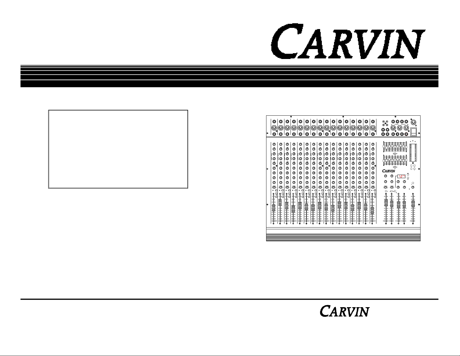
DX MIXER
HELPLINE
1-800-854-2235
8:30 To 4:30 Monday-Friday
Pacific Standard Time
USA
CARVIN
619-747-1710
15
16
1
LINE
LINE LINE LINE LINE LINE LINE LINE LINE LINE LINE LINE LINE LINE LINE LINE
MIC
DIR /
DIR /
DIR /
DIR /
DIR /
DIR /
DIR /
DIR /
DIR /
INSERT
INSERT
INSERT
INSERT
INSERT
INSERT
INSERT
LINE
LINE
LINE
LINE
LINE
LINE
1
2 3 4 5 6 7 8 9 10 11 12 13 14 15 16
654
654
654
MIC
MIC
MIC
MIC
7
3
7
3
7
3
3
8
2
8
2
8
2
2
9
9
9
1010
1010
1010
HI
HI HI HI HI HI HI HI HI HI HI HI HI HI HI HI
0
0
0
3
3
3
3
3
3
6
9
12 12
3
6
9
12 12
MID
300
100 5K
LOW
3
6
9
12 12
MON
1
3
2
MON
2
3
2
EFF
1
3
2
EFF
2
3
2
PAN
(1)L R(2)
1
10
+
5 5
0
700
0
0
PK
3
6
6
6
6
6
6
9
9
9
9
9
9
12 12
12 12
12 12
0
0
3
3
3
3
3
3
6
6
6
6
6
6
9
9
9
9
9
9
12 12
12 12
12 12
MID
MID
MID
700
700
2K
300
2K
300
2K
300
100 5K
100 5K
100 5K
LOW LOW LOW LOW LOW LOW LOW LOW LOW LOW LOW LOW LOW LOW LOW
0
0
3
3
3
3
3
3
6
6
6
6
6
6
9
9
9
9
9
9
12 12
12 12
12 12
MON
MON
MON
654
1
654
1
654
1
7
7
3
7
3
3
8
8
2
8
2
2
9
9
9
1010
1010
1010
MON
MON
MON
654
654
654
2
2
2
7
7
3
7
3
3
8
8
2
8
2
2
9
9
9
1010
1010
1010
EFF
EFF
EFF
654
654
654
1
1
1
7
7
3
7
3
3
8
8
2
8
2
2
9
9
9
1010
1010
1010
EFF
EFF
EFF
654
654
654
2
2
2
7
7
3
7
3
3
8
8
2
8
2
2
9
9
9
1010
1010
1010
PAN
0
PAN
0
PAN
(1)L R(2) (1)L R(2) (1)L R(2) (1)L R(2) (1)L R(2) (1)L R(2) (1)L R (2) (1)L R(2) (1)L R(2) (1)L R (2) (1)L R(2) (1)L R(2) (1)L R(2) (1)L R(2) (1)L R(2)
PK
PK
PFL
PFL
PFL
2
3
4
L-R
L-R
L-R
1-2
1-2
1-2
10
10
10
+ + + + + + + + + + + + + + +
MUTE
MUTE
MUTE
5 5 5 5 5 5 5 5 5 5 5 5 5 5 5 5 5 5 5
0
0
0
5
5
5
10
10
10
20
20
20
30
30
30
40
40
40
50
50
50
LINE
654
654
654
654
MIC
MIC
MIC
7
7
3
7
3
7
3
8
8
2
8
2
8
2
9
9
9
1010
0
3
6
9
0
3
6
9
MID
700
2K
0
3
6
9
MON
654
7
8
9
1010
MON
654
7
8
9
1010
EFF
654
7
8
9
1010
EFF
654
7
8
9
1010
0
PAN
PK
PFL
L-R
1-2
10
MUTE
0
5
10
20
30
40
50
9
1010
1010
1010
0
0
0
3
3
3
3
3
3
6
6
6
6
6
6
9
9
9
9
9
9
12 12
12 12
12 12
0
0
0
3
3
3
3
3
3
6
6
6
6
6
6
9
9
9
9
9
9
12 12
12 12
12 12
MID
MID
700
700
700
300
2K
300
2K
300
2K
100 5K
100 5K
100 5K
0
0
0
3
3
3
3
3
3
6
6
6
6
6
6
9
9
9
9
9
9
12 12
12 12
12 12
MON
MON
1
654
1
654
1
654
7
3
7
3
7
3
8
2
8
2
8
2
9
9
9
1010
1010
1010
MON
MON
654
654
654
2
2
2
7
3
7
3
7
3
8
2
8
2
8
2
9
9
9
1010
1010
1010
EFF
EFF
654
654
654
1
1
1
7
3
7
3
7
3
8
2
8
2
8
2
9
9
9
1010
1010
1010
EFF
EFF
654
654
654
2
2
2
7
3
7
3
7
3
8
2
8
2
8
2
9
9
9
1010
1010
1010
0
PAN
0
PAN
0
PK
PK
PK
PFL
PFL
PFL
5
6
7
L-R
L-R
L-R
1-2
1-2
1-2
10
10
MUTE
MUTE
MUTE
0
0
5
5
10
10
10
20
20
20
30
30
30
40
40
40
50
50
50
DIR /
INSERT
INSERT
INSERT
INSERT
LINE
LINE
LINE
LINE
654
654
654
MIC
MIC
MIC
MIC
7
3
7
3
7
3
3
8
2
8
2
8
2
2
9
9
9
1010
1010
1010
0
0
0
3
3
3
3
3
3
6
9
12 12
0
3
6
9
12 12
MID
700
300
100 5K
0
3
6
9
12 12
MON
1
3
2
MON
2
3
2
EFF
1
3
2
EFF
2
3
2
PAN
0
PK
8
10
0
5
3
6
6
6
6
6
6
9
9
9
9
9
9
12 12
12 12
12 12
0
0
3
3
3
3
3
3
6
6
6
6
6
6
9
9
9
9
9
9
12 12
12 12
12 12
MID
MID
MID
700
700
2K
300
2K
300
2K
300
100 5K
100 5K
100 5K
0
0
3
3
3
3
3
3
6
6
6
6
6
6
9
9
9
9
9
9
12 12
12 12
12 12
MON
MON
MON
654
1
654
1
654
1
7
7
3
7
3
3
8
8
2
8
2
2
9
9
9
1010
1010
1010
MON
MON
MON
654
654
654
2
2
2
7
7
3
7
3
3
8
8
2
8
2
2
9
9
9
1010
1010
1010
EFF
EFF
EFF
654
654
654
1
1
1
7
7
3
7
3
3
8
8
2
8
2
2
9
9
9
1010
1010
1010
EFF
EFF
EFF
654
654
654
2
2
2
7
7
3
7
3
3
8
8
2
8
2
2
9
9
9
1010
1010
1010
PAN
0
PAN
0
PAN
PK
PK
PFL
PFL
PFL
9
10
11
L-R
L-R
L-R
1-2
1-2
1-2
10
10
10
MUTE
MUTE
MUTE
0
0
0
5
5
5
10
10
10
20
20
20
30
30
30
40
40
40
50
50
50
1
14
MIC MIC
MIC13MIC12MIC11MIC10MIC9MIC8MIC7MIC6MIC5MIC4MIC3MIC2MIC
DIR /
DIR /
DIR /
DIR /
DIR /
INSERT
INSERT
LINE
LINE
654
654
654
MIC
MIC
7
7
3
7
3
8
8
2
8
2
9
9
9
1010
1010
1010
0
0
0
3
3
3
3
3
6
6
6
6
6
9
9
9
9
9
12 12
12 12
0
0
0
3
3
3
3
3
6
6
6
6
6
9
9
9
9
9
12 12
12 12
MID
MID
700
700
700
2K
300
2K
300
2K
100 5K
100 5K
0
0
0
3
3
3
3
3
6
6
6
6
6
9
9
9
9
9
12 12
12 12
MON
MON
654
1
654
1
654
7
7
3
7
3
8
8
2
8
2
9
9
9
1010
1010
1010
MON
MON
654
654
654
2
2
7
7
3
7
3
8
8
2
8
2
9
9
9
1010
1010
1010
EFF
EFF
654
654
654
1
1
7
7
3
7
3
8
8
2
8
2
9
9
9
1010
1010
1010
EFF
EFF
654
654
654
2
2
7
7
3
7
3
8
8
2
8
2
9
9
9
1010
1010
1010
0
PAN
0
PAN
0
PK
PK
PK
PFL
PFL
PFL
12
13
L-R
L-R
L-R
1-2
1-2
1-2
10
10
MUTE
MUTE
MUTE
0
0
5
5
10
10
10
20
20
20
30
30
30
40
40
40
50
50
50
DIR /
INSERT
INSERT
INSERT
LINE
LINE
LINE
654
654
654
MIC
MIC
MIC
7
3
7
3
7
3
8
2
8
2
8
2
9
9
9
1010
1010
1010
0
0
0
3
3
3
3
3
3
6
6
6
6
6
6
9
9
9
9
9
9
12 12
12 12
12 12
0
0
0
3
3
3
3
3
3
6
6
6
6
6
6
9
9
9
9
9
9
12 12
12 12
12 12
MID
MID
MID
700
700
700
300
2K
300
2K
300
2K
100 5K
100 5K
100 5K
0
0
0
3
3
3
3
3
3
6
6
6
6
6
6
9
9
9
9
9
9
12 12
12 12
12 12
MON
MON
MON
1
654
1
654
1
654
7
3
7
3
7
3
8
2
8
2
8
2
9
9
9
1010
1010
1010
MON
MON
MON
654
654
654
2
2
2
7
3
7
3
7
3
8
2
8
2
8
2
9
9
9
1010
1010
1010
EFF
EFF
EFF
654
654
654
1
1
1
7
3
7
3
7
3
8
2
8
2
8
2
9
9
9
1010
1010
1010
EFF
EFF
EFF
654
654
654
2
2
2
7
3
7
3
7
3
8
2
8
2
8
2
9
9
9
1010
1010
1010
PAN
0
PAN
0
PAN
0
PK
PK
PK
PFL
PFL
PFL
14
15
16
L-R
L-R
L-R
1-2
1-2
10
0
5
1-2
10
10
MUTE
MUTE
MUTE
0
0
0
5
5
5
10
10
10
20
20
20
30
30
30
40
40
40
50
50
50
16
15141312111098765432
OPERATION MANUAL
Manual No. 96-16420
Revision 1.0
Mar. 1994
Made in USA
TAPE SEND
L R
C
STEREO RETURNS
B
R
L
A
+12
8
4
0
4
8
–12
125 250 500631K 2K 4K 8K
OUT
LEFT
+12
8
4
0
4
8
–12
125 250 500631K 2K 4K 8K
OUT
RIGHT
654
3
7
3
2
2
8
1
1
9
0 10
010
MON
MON 1
MON 2
SENDS
654
7
3
3
2
8
2
1
9
1
0 10
0 10
EFF 1 BEFF 2
SENDS
0
LR
SUB 2
SUB 1 MON 1
PAN
SUBS
MUTE
MUTE
+10
+10
0
0
5
5
10
10
20
20
30
30
40
40
50
50
SUB 1 SUB 2
SUB MIX
BAL SENDS
MON 1 EFF 1 EFF 2
MON 2
LEFT/3 RIGHT/4 MAIN
CNTRL
RM
SUB 1 PHONESSUB 2
IN
IN
DX1642
654
127 DIGITAL EFFECTS
7
8
9
16 BIT DIGITAL AUDIO
654
654
7
7
3
3
8
2
8
2
9
1
9
1
0 10
A
STEREO
RETURNS
0
654
7
3
3
2
8
2
1
9
1
LR
0 10
MAIN
STEREO
+10
+10
0
0
5
5
10
10
20
20
30
30
40
40
50
50
L/3 R/4
STEREO MASTERS
12V
SENDS
LAMP
POWER
PWR
CLIP
+6
+3
0
-3
16K
-6
-9
-12
-15
-20
L
R
METERS
16K
MON
SUB
1 2
1 2
L R
MAIN
BYPASS 0
REVERB Small 1 - 10
Medium 11 - 20
Large 21 - 30
+ Chorus 31 - 40
SELECT
+ Delay 41 - 50
+ Flange 51 - 60
Gated 61 - 70
Ambiance
71 - 80
DELAYS 30-500ms 81 - 99
654
7
8
9
0 10
MIC48V
654
654
7
3
7
2
8
8
PFL
1
9
9
0 10
0 10
PHONES
C / TAPE
CNTRL RM LEVEL
+10
0
5
10
20
30
40
50
MAIN
(1-4)
Record the serial number of your DX Mixer in the space provided below:
Serial No._________________ Invoice Date________________
1-800-854-2235
Page 2

RECEIVING INSPECTION
INSPECT YOUR DX MIXER FOR ANY DAMAGE which may have occurred during ship-
ping. If any damage is found, notify the shipping company and call CARVIN immediately.
SAVE THE CARTON & ALL PACKING MATERIALS. In the event you have to reship
your mixer, always use the original carton and packing material. This will provide the best
possible protection for your unit during shipment. CARVIN and the shipping company are
not liable for any damage caused by improper packing.
TABLE OF CONTENTS
P A G E
RECEIVING INSPECTION ................................................................. i
TABLE OF CONTENTS .................................................................... ii
FOR THE NEW OWNER ................................................................. 1
SAVE YOUR INVOICE. It will be required for warranty servicing of your unit. Always
check your invoice against the items you have received.
SHIPMENT SHORTAGE. If you find items missing, it may be that they were shipped
separately. Please allow several days for the rest of your order to arrive before inquiring.
If you determine (after allowing an appropriate amount of time) you have not received all
the items you ordered, please call CARVIN.
Carvin’s USA toll free number: 800-854-2235
QUICK START UP .......................................................................... 2
CHANNEL FEATURES ..................................................................... 3
MASTER SECTION CONNECTORS ................................................... 7
MASTER SECTION FEATURES ......................................................... 9
INTERNAL DSP EFFECTS PROCESSOR ............................................ 13
SETTING UP YOUR SOUND SYSTEM .............................................. 15
SAMPLE MIXER CONFIGURATIONS ............................................... 19
BLOCK DIAGRAMS ....................................................................... 25
DX MIXER PARTS LIST ................................................................. 27
DX MIXER TECHNICAL SPECIFICATIONS ....................................... 33
WARRANTY INFORMATION .......................................................... 34
Page 3
FOR THE NEW OWNER
TO CHANGE OPERATING
VOLTAGE UNPLUG POWER
CORD AND REMOVE AND
ROTATE FUSE HOLDER.
Congratulations on your selection of CARVlN products: “The Professional’s
Choice.” Your new DX series console demonstrates CARVIN’s commitment to
producing the highest quality & most sophisticated engineering in the audio
industry today. Its wide acceptance and use by industry professionals illustrates
the basis for CARVIN’s recognition as “The Professional’s Choice.”
Professionalism can only be measured by people from the results they achieve
through their efforts and knowledge. It is not something that automatically happens when buying a new or more sophisticated console. Rather, it’s what you
do with the equipment and how well you do it that ultimately makes the point.
We are certain your new CARVlN console will deliver the performance necessary for you to achieve solid results, and ultimately enjoy a high degree of professional gain and enjoyment.
To compliment your new console and help you acquire that knowledge, we’ve
included this manual. All of the information you need to be up and running is
right here! You’ll find using this manual easy and convenient. We’ve gone to
great lengths to make it so. We’ve attempted to present the technical aspects of
your new console accurately and in “plain English”. But, if you have any questions that are not answered here, please call us at our toll free number. Our
sales staff is well versed in the technical aspects of our products and are waiting
to assist you with any questions you may have. We sincerely wish to ensure
your complete satisfaction and enjoyment with your new console.
If you would like to comment on features or performance of your new console,
please feel free to contact us. Comments from our customers has helped us
improve and further develop our products and our business.
QUICK STA RT UP
If you’re like most new owners, you’re probably in a hurry to plug your DX mixer
in and use it. Here are some brief instructions to get you going quickly. With the
mixer unplugged, turn the unit off and complete the following procedures:
CONNECTING AC POWER TO YOUR MIXER (Non-Powered Models Only)
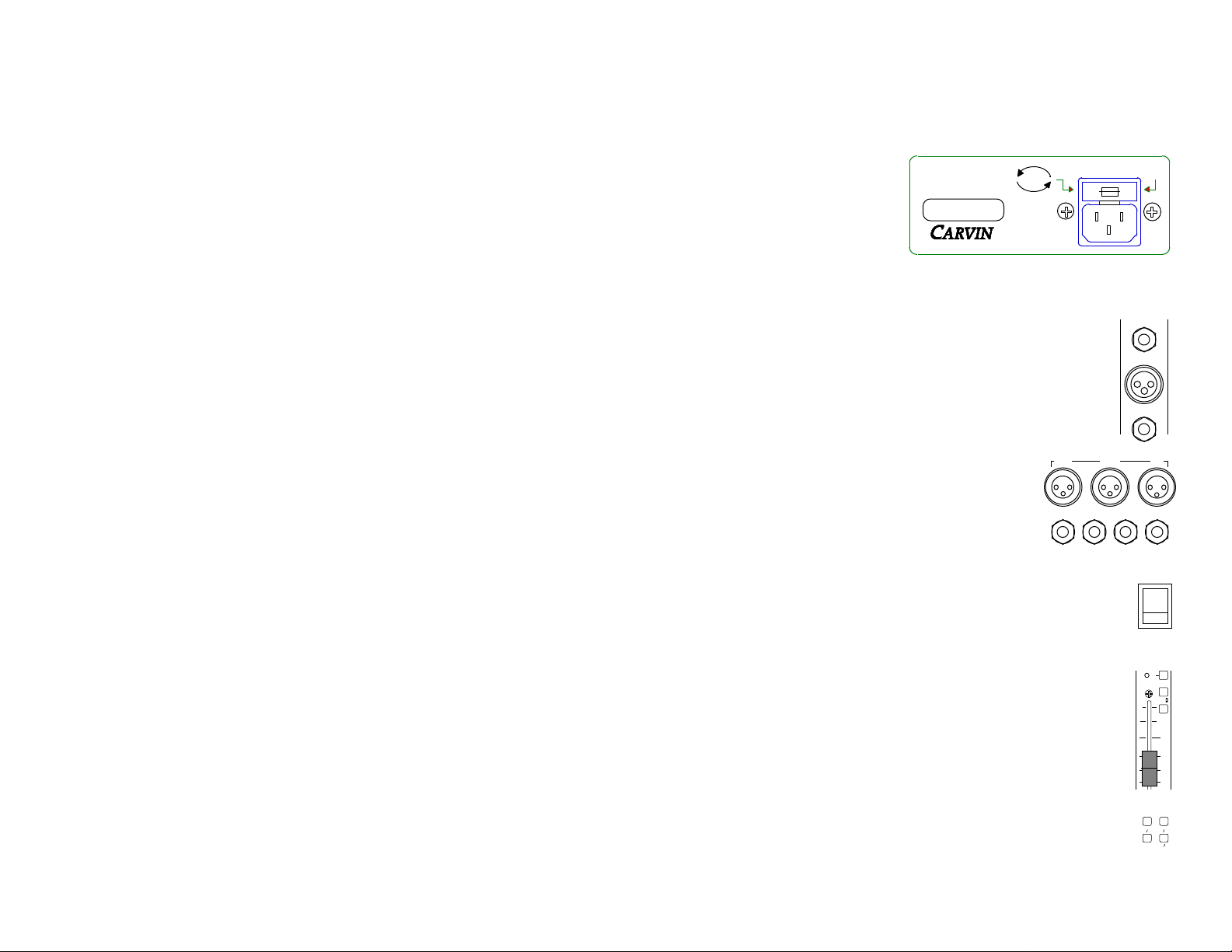
Check and change if necessary the
AC Line Voltage to the proper voltage. The AC Line Voltage is listed
on the fuse holder in the AC connect
receptacle. To change the AC operating voltage remove and rotate the
fuse holder so that the desired volt-
SER. NO. 000000
Toll Free 1-800-854-2235
120V
240V
MADE
IN THE
AUS
50-60 Hz 140VA
120-240 VAC
age reads right side up. Use only a grounded (3 prong) power outlet to prevent a
shock hazard. This gives the quietest grounding for your mixer. Powered mod -
els do not offer 120/240 voltage switching. They must be ordered for the
appropriate line voltage.
CONNECTING INPUTS TO YOUR MIXER
For low level balanced devices such as microphones, plug into the
balanced MIC XLR input. Use a 3 conductor shielded mic cable. For
high output level devices such as Tape Recorders, CD’s, Keyboards
and Wireless mic receivers, plug into the LINE 1/4” input jacks. Use a
2 conductor shielded cable.
CONNECTING OUTPUTS FROM YOUR MIXER
Connect the L E F T / 3 and R I G H T / 4 balanced XLR outputs
to the balanced XLR inputs on your power amp. If your
power amp can not accommodate balanced XLR connections, there are unbalanced 1/4” phone jacks on the rear of
your D X Series mixer (except powered models).
2 Amp Fuse
115V
LEFT/3 RIGHT/4 MAIN
SUB 1 PHONESSUB 2
MIC
CNTRL
RM
230V
LINE
DIR /
INSERT
FUSE
Please, send in the warranty card. Although it is not absolutely necessary to
ensure warranty protection, it will allow us to better know how you are using our
equipment while keeping a ready reference for our files. Sending in the warranty
card also helps us to mail out literature and information that may be of interest to
you as a professional musician. Let us know where you are so we can keep in
touch!
In this manual there are plenty of diagrams and descriptions to aid you in understanding your new console. So, with this manual in hand you hold the key to
proper operation of your new console, and to achieve truly professional results.
May you enjoy many years of enjoyment, success, and fun with your new
CARVIN console!
Carvin’s toll free number: 800-854-2235
TURNING YOUR MIXER ON
Adjust all faders and gain controls of your mixer to the off position. Adjust
all EQ tone controls—Hi, MID and LOW and the 9 Band Graphic EQ to
their center positions. Adjust all the Channel P A N Assign controls to
their center positions. Turn the mixer’s power switch to the on position
and check that the power indicator LED illuminates. Your mixer is now on
and ready to operate.
SETTING YOUR CHANNEL LEVELS
Bring up the level of the LINE MIC gain control until the channel peak
indicator LED PK illuminates, then back off this control by one number. It
is normal for the peak indicator to occasionally flash during use. Set the
L - R / 1 - 2 switch to the L-R STEREO MASTERS. Bring up the channel
fader level to a nominal setting of “0”, this is Unity Gain for the channel
fader.
SETTING YOUR MASTER LEVELS
Bring up the STEREO MASTER faders to the desired volume level, and
monitor the levels by depressing the L / R button in the M E T E R S s e l e c t
block.
10
+
POWER
PK
METERS
MON
1 2
MAIN L R
PFL
L-R
1-2
MUTE
5
0
5
10
SUB
1 2
Page 4
CHANNEL FEAT U R E S
Gnd
MIC
1
LINE
DIR /
INSERT
1. LINE INPUT JACK - This 1/4” phone jack is designed
to accept unbalanced line or low level signals. This input
will accept both high and low impedance input signals. It
1
is sensitive enough to directly accept the output of a guitar or similar instrument with out the need for external
direct input boxes or preamplifiers, yet will also accept
line level signals such as pre amp outputs from ampli-
2
fiers or keyboard systems.
2. XLR MIC INPUT - The XLR input is designed for balanced low impedance (microphone) input signals. This
allows for long microphone cable runs without significant
3
signal or high frequency loss. The input channel consists of a balanced differential amplifier which works to cancel externally generated noise. The XLR connector is wired as per the industry standard, pin one is
ground, pin two is high (positive signal) and pin three is low (negative signal).
Phantom power is available on every XLR microphone input. This will allow you
to run condenser microphones directly off of your DX Series mixer. A switch
located in the master section will allow you to engage the phantom power.
NOTE: Make sure the phantom power is switched off before connecting or disconnecting microphones to your mixer. It is recommended that you allow the
phantom power to discharge for about 10 seconds before making any microphone connections.
3. DIRECT/INSERT JACK - The channel patch jack allows you access to that
channel for inserting different effects or signal processing equipment. Usually
this jack is used with such signal processing equipment as compressors,
limiters, delays, EQ’s, etc. These
devices can help with many problem
situations requiring special attention.
DIR /
INSERT
Send
GndRtn
FULL INSERT
(Signal Interuption)
Direct Out
HALF INSERT
(No Signal Interuption)
For instance, if you have a vocal input
requiring a very precise equalization (tone shaping) you may wish to “patch in” a
more elaborate equalizer than the standard tone controls found on the channels. This would allow you the ability to affect that particular channel without
affecting adjacent channels.
And, you achieve your objective of fine tuning that particular vocal. The jack is configured: Tip to return and Ring to
send.
To use the D I R / P A T C H for a
direct channel output, insert
the plug only halfway into the
jack.
Carvin offers the A P 1 cable which is a 6” adapter which plugs into the
DIR/PATCH giving a 1/4” jack for the “Send” and a 1/4” jack for the “Receive”
portions of the Patch feature.
4. GAIN CONTROL - The best way to use this control
is to start by rotating the gain control fully counterclockwise. Then while source material is active, bring up the
4
gain control until the peak indicator illuminates and then
back off until the peak PK indicator just stops flashing.
This provides the maximum usable gain for the input. If
5
the signal is too strong the red LED peak PK indicator
will light. Rotate the LINE / MIC gain control counterclockwise until the PK light just goes out. Setting the
input gain controls just below the peak threshold will set
6
the input gain to deliver just the right level to the channel. It is alright if the peak indicator occasionally flash-
1
es during use, as it is set to come on at -6dB below
clipping. Rotating the LINE / MIC gain control exces-
7
sively counterclockwise beyond the point at which the
PK light goes out will drop the signal too much and you
8
may not have enough gain, or the noise floor (hiss)
LINE
MIC
3
2
HI
6
9
6
9
MID
500
300 5K
LOW
6
9
0
3
12 12
0
3
12 12
1.6K
0
3
12 12
1
654
7
8
9
1010
3
6
9
3
6
9
3K
3
6
9
may become audible. Once this adjustment has been made you should not
need to adjust this control again unless the signal changes at the source.
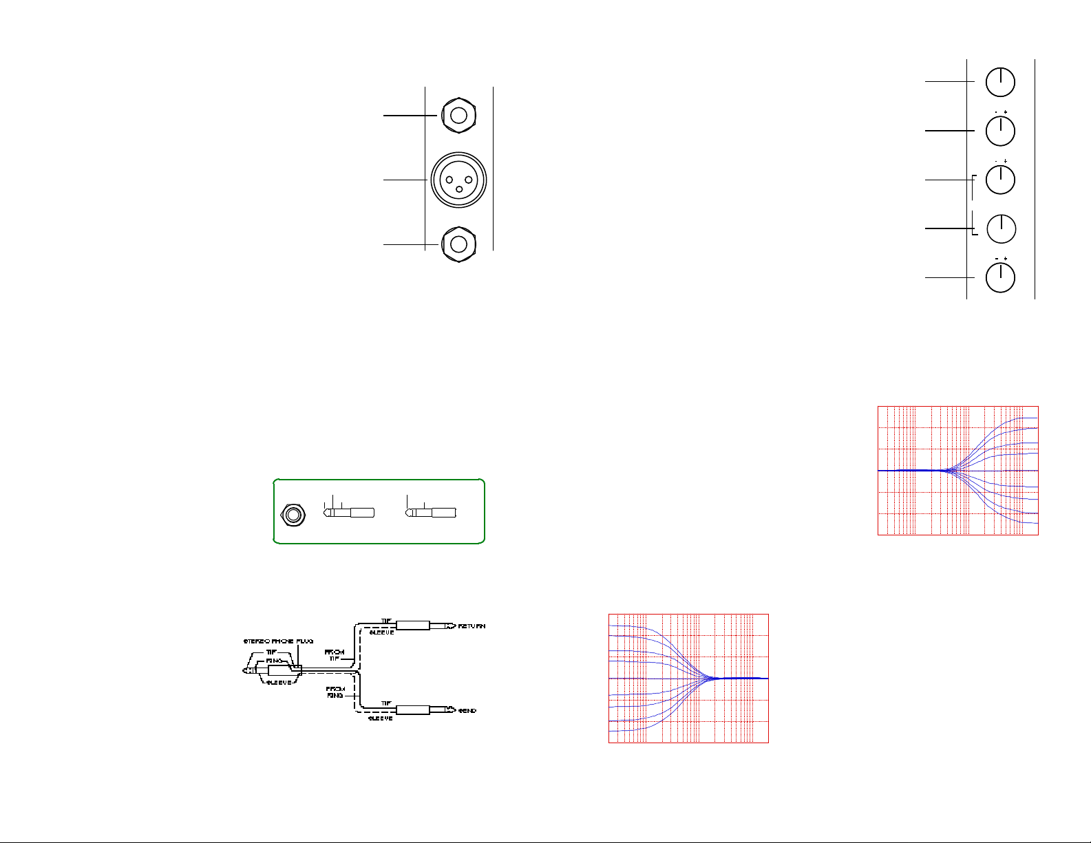
5-8 CHANNEL EQ - The Channel Equalizer is a very precise set of tone controls. The H I or “Treble” control is at the top of the Channel Equalizer controls.
The M I D and MID sweep controls are in the center. And, the L O W or bass
control is at the bottom of this array. Use these
knobs to modify the tone of the signal feeding
this particular channel. It is most important that
you know that the flat (or neutral) setting for
each EQ control is “0” or (center detent). If you
have any doubt about how to set the them then
always set the channel EQ controls flat (i.e.
“ 0 ” ) .
How a tone control works is basically similar to
a volume control. The difference being that a
tone control literally controls the volume of a
dB
+15
+10
+5
0
-5
-10
-15
20 100 1K 10K 20K
HI CONTROL CUT & BOOST
Frequency/Hz
specified frequency range. For instance, the H I, or treble control, when turned
up will increase the volume of the high frequencies (at a l2kHz frequency shelf).
Likewise, the L O W, or bass, control adjusts the volume at a 80Hz frequency
dB
+15
+10
+5
0
-5
-10
-15
20 100 1K 10K 20K
LOW CONTROL CUT & BOOST
Frequency/Hz
shelf and therefore can be used to either
emphasize or quiet the low range of an input
signal. The M I D has a variable frequency
range from 300Hz to 5KHz this allows you to
fine tune the mid-range frequencies. This is
especially useful as the mid-range is usually
the most critical “problem range”. The EQ
controls allow you to adjust the volume ±12dB
at their center frequencies. Direct connection
of electric guitars usually sound best with full
MID cut (-12dB) at 500Hz, and full treble “H I”
boost (+12dB). Experimentation is in order.
Usually these controls are used as a means of compensating for the imperfect
response of various microphones in order to achieve the most natural sounding
Page 5
12 12
(1)L R(2)
9
10
11
12
13
(1)L R(2)
PFL
PK
10
50
40
30
20
10
0
5
L-R
1-2
+
1
MUTE
14
15
16
17
18
5
15
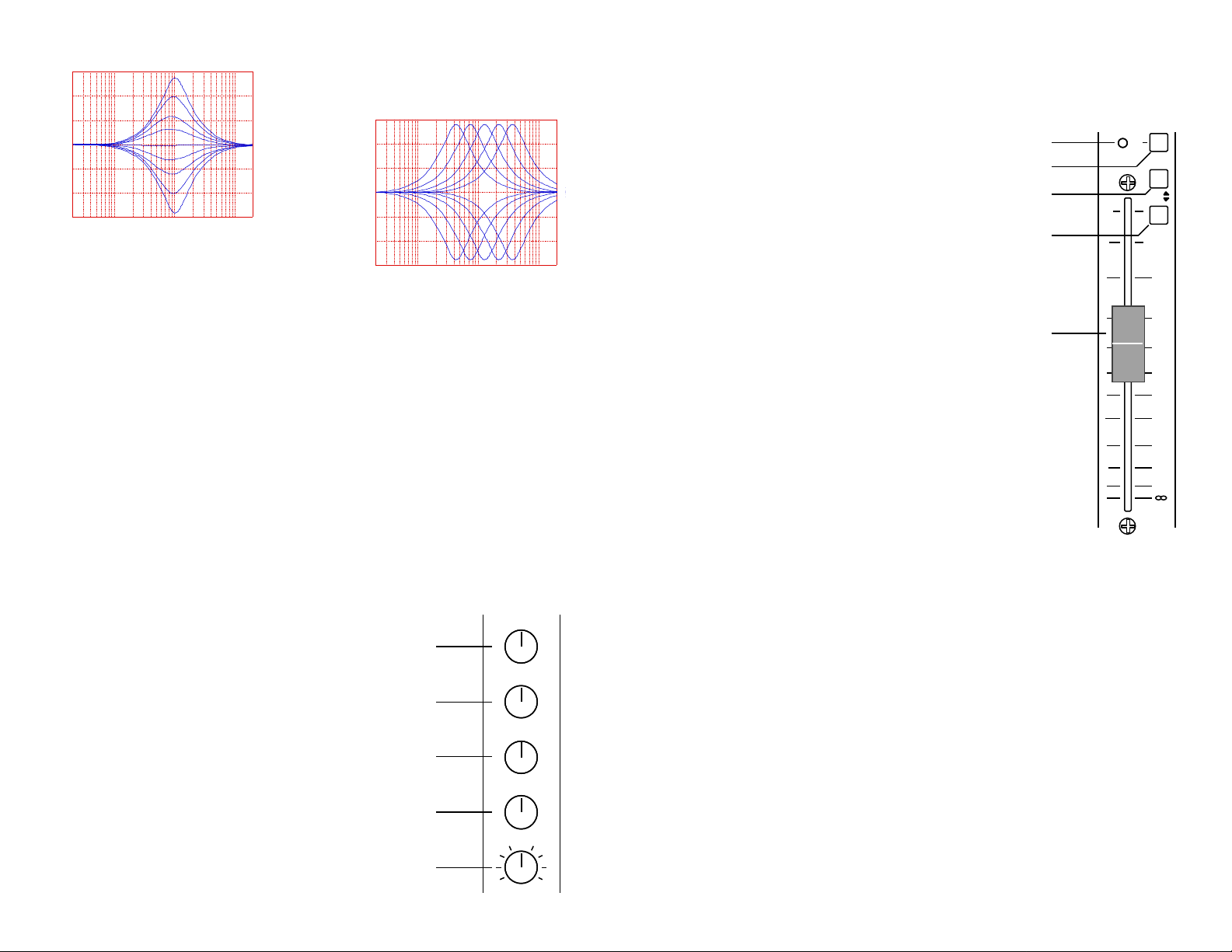
MID CONTROL FREQ. SWEEP
dB
6
+15
+10
+5
0
-5
-10
-15
20 100 1K 10K 20K
MID CONTROL CUT & BOOST
Frequency/Hz
ble through the use of your Channel Equalizer
is part of the overall art of professional mixing
and recording.
response of the sources you are mixing. If
you find yourself making excessive adjustments with these controls you may want to try
using either a
d i f f e r e n t
m i c r o p h o n e
or a different
mic location.
Making an
i n s t r u m e n t
sound as natural as possi-
dB
+15
+10
+5
0
-5
-10
-15
20 100 1K 10K 20K
Frequency/Hz
9-12 MONITOR and EFFECTS BUS SENDS - The input channel’s monitor and effects
send controls are simply volume controls for setting up four “side mixes” which are independent of the main mix. They are used to set up mixes for stage monitors and various
effects units. Each channel has two monitor send controls (MON 1& MON 2). These
control the volume of that channel’s signal in the MON 1& MON 2 monitor mixes. The
monitor level control on each channel adjusts the relative volume of that channel in the
overall monitor mix. So, it is possible that you could set up a monitor mix that is entirely
different from the main mix. For instance, you might have a vocal “out front”, or louder,
in the MON 1 mix to allow a singer to concentrate on their vocals while feeding a relatively low level of that same vocal to the main mix. Since stage monitors are typically
right next to the microphones, they are usually the mix most susceptible to feedback during a performance. Because of this we recommended that you use caution when
adjusting monitor levels during a live performance. It takes a certain amount of “feel” to
set up a good monitor mix without getting ringing or outright feedback. However, with
experimentation and practice you will soon be able to get consistently good monitor
mixes. The MON 1& MON 2 signals are taken “pre fader” so that the channel fader has
no effect on the signal level sent to the monitor mixes.
The EFF 1 a n dEFF 2 controls send the channel signal to two more “side mixes” for use
in feeding effects devices such as the internal DSP unit or
outboard effects. The “Effects Send” signals are taken “post
fader”. This means that when the channel fader is reduced,
so is the effects signal. The EFF 2control feeds the internal
DSP system. By raising this control, you will send the channel’s signal to the internal Digital Reverb unit. However, the
DSP effect will not be heard until the DSP return control
(effects return RTN A) is raised (see the System Master
Section). The internal DSP return is automatically defeated
when an outboard processor is plugged in the RTN A j a c k .
13. PAN CONTROL - The P A N control allows you to set
the relative volume level of each channels send to the L / 3
and R / 4 master stereo outputs or to the Sub 1 and Sub 2
Sub Mixes, depending on the position of the L - R / 1 - 2s e l e c t o r
switch. Panning the channel all the way left will send the
signal only to the L / 3 stereo master or the SUB 1 m a s t e r ;
panning hard right will send signal only to the R / 4 s t e r e o
master or the SUB 2m a s t e r .
MON
MON
EFF
EFF
PAN
14. PEAK INDICATOR - Use the channel peak P K indicator to find the best setting
for the LINE/MIC gain control. The P K warning light will flash whenever a signal
exceeds a level of +12dBv anywhere within the channel. This light is used to warn
the operator whenever signal levels are so high that there is risk of distortion.
Whenever you see the P E A K LED flashing you should
reduce the setting of the LINE / MIC gain control, until
the LED just stops flashing. It is just as important to be
sure not to set the G A I N control too low. Setting the
channel gain too low will prevent you from achieving the
excellent signal-to-noise performance that the mixer is
capable of delivering. Note that the P E A K i n d i c a t o r
responds to overloading at the mic and line preamps, the
channel EQ, and the channel fader amp. Use this indi-
cator to set the GAIN controls on all of the channels as
your first step whenever setting up a mix. Careful use of
these controls will assure you of a distortion, free mix
with the lowest possible noise.
15. THE PFL CONTROL - The channel P F L (“pre fader
listen”) switch allows you to solo audition each channel or
group of channels to the control room monitors (or
phones) without affecting the main mix. The P F L s w i t c h
lets you to hear only the channel (or channels) selected,
even though you may be sending many signals through
the mixer to the main mix. This is an extremely useful
mixing feature that will help you to fine tune the EQ on
individual sources, even during a performance. You can
also combine solos. This means that you can depress
one or more P F L switches in order to listen to combina-
tions instruments to be sure their levels are good and
that they are blending well. Whenever you depress a
P F L switch the Peak LED will come on to indicate
that that channel is soloed. Also, whenever any chan-
nel or sub group is soloed, another master LED will light up in the System Master
Section to indicate that you are in a solo mode and that the normal control room feed
has been interrupted by the solo system.
654
1
7
3
8
2
1
9
10
0
654
2
7
3
8
2
9
1010
654
1
7
3
8
2
9
1010
654
2
7
3
8
2
9
1010
0
16. CHANNEL ASSIGN SWITCH - This switch gives you the option of assigning a
channel to a sub mix or directly to the two-track output. Depressing this switch will
assign the channels output to the Sub Mixmaster faders, thus giving you the option
of grouping various channels as a side mix to the two-track.
17. THE MUTE SWITCH - When the channel M U T E switch is depressed the channels signal is totally removed from the system, including the monitor and effects side
mixes. The only control that is not muted is the P F L, thus allowing you to audition a
channel before folding it into the any of the active mixes.
18. THE CHANNEL FADER - The Channel Fader controls the volume of each
channel. It is accurately calibrated and adjusts the level of each channel as it is sent
to the sub mix, two-track, and effects mixes. A “normal” setting for the channel
faders would be between about -10 and +5 on the fader markings. This means that
usually you will be operating your channel faders relatively high compared to your
2 T R A C K faders. Keeping the channel faders high will help assure the most quiet
performance and best overall sound from your console.
Page 6

MASTER SECTION CONNECTORS
TAPE SEND
L R
TAPE SEND
BAL SENDS
MON 1 EFF 1 EFF 2
MON 2
SENDS
12V
LAMP
6. SUB 1 & SUB 2 OUTPUTS - These are your direct submix sends off of the SUB 1 & SUB 2, SUB MIX faders. By
using these outputs in conjunction with the L E F T / 3 &
R I G H T / 4 XLR outputs you can setup four independent sub
mixes for multi track recording.
SUB 1 SUB 2
L R
C
STEREO RETURNS
B
L
R
A
LEFT/3 RIGHT/4 MAIN
SUB 1 PHONESSUB 2
CNTRL
RM
POWER
1. EFF1 AND EFF2 SENDS - These jacks are used to drive outboard signal processors such as digital delays, reverb units,
chorus effects, etc. The Effects Send, E F F 1 and E F F 2, jacks
EFF 1 EFF 2
are used as an output from your console to drive the input of the
effect you desire to use. By adjusting your Channel EFF1 and
EFF2 Controls, and Master Section EFF1 and EFF2 Controls of your mixer you
can vary the output of the Effects Send to drive your effect with as much, or as
little signal as required for optimum performance.
2. BALANCED MONITOR SENDS - These two 1/4” phone jacks deliver a
Balanced line level signal to drive the inputs of your monitor
power amps. For optimum performance use balanced 1/4”
MON 1
phone (Tip/Ring/Sleeve) patch cables. Using balanced connections will reduce cable hum and will allow 6dB more gain when
driving balanced inputs. By adjusting your Channel MON1 and
MON2 Controls, and Master Section MON1 and MON2 Controls of your unit you
can mix and vary the output of the Monitor Sends to drive your power amp to the
desired volume level.
3. TAPE SEND - The TAPE SEND RCA connectors are “pre-amp” outputs from
the 2-Track Master controls. These line level outputs may be used to drive a
tape deck for stereo recording while simultaneously using the
LEFT/3 and RIGHT/4 XLR outputs to drive you main power amps.
4. TAPE RETURN - These RCA connectors are pre-amp inputs
to the RTN C TAPE control. Use these jacks for playback of
stereo recordings. Use the RTN C TAPE to control the level of
this return to the 2-Track buss.
5. STEREO RETURNS - These 1/4” phone jacks are used to
STEREO RETURNS
receive the outputs of your effects devices. RTN A is used for
the optional internal DSP effects unit. By inserting into RTN A
with a 1/4” phone plug you automatically disable the internal
effects unit.
SENDS
BAL SENDS
B
A
MON 2
RL
7. LEFT & RIGHT OUTPUTS - These two
XLR jacks are balanced line level outputs from
LEFT/3 RIGHT/4 MAIN
the 2-Track Master controls. These pre-amp
outputs should be used to drive your power
amps for your main house system.
8. MONO MAIN OUTPUTS - This balanced XLR output contains the mix of
your DXs four sub mixes. Use this output to deliver a mono output to your
power amps when running mono systems.
12. AUXILIARY MASTER OUTPUTS - T h e r e
MASTER OUTPUTS
are an extra set of auxiliary master outputs located on the back panel of your D X series mixer
(non-powered models only). These are 1/4”
unbalanced equvilants to the XLR L E F T / 3,
R I G H T / 4 and M A I N outputs located on the top
(CH 3) (CH 4)
RIGHTLEFT
MAIN
(MONO)
panel.
9. PHONES & CONTROL ROOM - Use these two stereo jacks
to monitor the signal at various points in your mixer. The level of
240V
230V
CNTRL
RM
PHONES
this output is controlled by the PHONES CNTRL RM LEVEL
knob in the master section above the M A I N fader. To select
what you are listening to depress one or more of the selector
switches directly below the VU METERS.
10. 12V LAMP XLR CONNECTOR - The XLR connector labeled
12V LAMP (located at the very top right of the system master) is a
12V
LAMP
receptacle for a XLR type 12 volt Mini-Lamp. This light is used to
provide illumination for the console when it is used in low light conditions. It operates on 12 volts and provides an excellent source of
light where house lighting is kept low. The mini-light is offered by
CARVIN and may be purchased for $25.00 (specify Model GX12V).
11. POWER ON/OFF SWITCH - This is the main AC power switch
POWER
for your D X mixer. When you flip this switch to the on position you
should notice that the power indicator LED illuminates. It is a good
practice to bring the main faders all the way down before turning the
console on.
13. MIDI IN & MIDI THRU - There are a set DIN type
MIDI connectors located on the back panel of your D X
240V
230V
MIDI
Series mixer. These connectors give you the option of
controlling the internal DSP Multi Effects processor via
MIDI.
MIDI IN MIDI THRU
Page 7

MASTER SECTION FEAT U R E S
1. THE VU METERS - The VU meters display the relative
output signal levels of various sections of your D X mixer. A
group of four meter selector switches are located at the VU
LED array. One or more of these switches can be selected
CLIP
to monitor the desired outputs. The P F L switches in the
channels of D X mixer override the meter selector switches,
so anytime the P F L indicator LED is on the meters are displaying the P F L l e v e l .
It is important to realize that there is no single correct reading
for the VU meters. Rather, the most important use of the
meters is to display relative signal levels. You will often
glance at the meters simply to determine if there is a signal
present at an output. It is entirely possible to have very little
or no meter movement but be producing a perfectly accept-
able signal level. In church applications there are many
occasions when the VU meters will be just barely moving,
but a perfectly acceptable signal level is being reached.
This is normal, and the VU meter is simply indicating that you
are using very little of the available output level of the cons o l e .
On the other hand, a rock band may produce levels that would indicate from -6
to +3 VU. Although it is perfectly normal for high level audio signal peaks to indicate on the meter up into the “orange” +3dB zone, you should try to keep the
meter reading comfortably at or around “0” VU as a maximum value.
For recording applications the meters and their calibration are more important
than for sound reinforcement use. This is because you usually want to squeeze
as much signal onto tape as possible without saturating (distorting) the tape. You
normally want the meters on the mixer to be calibrated the same, and therefore to
read the same, as the meters on the recorder simply to allow you to keep your
eyes on the mixer and not have to watch the meters at the recorder all the time.
On the powered version of the D X mixer the red C L I P indicator led acts as a
power amp clip indicator, this serves as a guide to the maximum output level of
the board. Note: if the red C L I P meters come on and stay on, and you are
getting no output from the internal power amps, your D X mixer has gone
into its protection mode. The cause of this is usually one of two problems. The
amp may be running too hot, this can happen if there is poor ventilation through
the intake and exhaust cooling vents. Check for obstructions, and allow at least
3” of free air space around vents. Turn the mixer off and allow it a few minutes to
cool down. The other common cause for the amp to protect is if it is connected to
shorted speaker cables or an inappropriate speaker load. The internal FET amps
can safely handle speaker loads down to 4Ω. If your amp goes into protect mode
for a shorted cable turn the mixer off, locate and replace the bad cable and then
turn the mixer back on.
CAL CAL
+6
+3
0
-3
-6
-9
-12
-15
-20
L
MON
PWR
METERS
SUB
1 2
1 2
MAINRL R
2. THE GRAPHIC EQUALIZERS -
Each D X mixer is provided with two nine
band graphic equalizers. Each graphic
EQ has a bypass switch and LED status
indicator located below it. The LED is
illuminated when the graphic EQ is
switched into the signal path. The
graphic EQ’s are dedicated to the L/3 &
R/4 two-track outputs of the mixer.
The 9 band Graphic Equalizers in the
D X mixers provides a wide degree of
tonal flexibility. To properly use the
Graphic EQ (equalizer), set all sliders to
their center position. With the sliders at
this position, there is no effect on the
+12
8
4
0
4
8
–12
125 250 500631K 2K 4K 8K
OUT
LEFT
IN
+12
8
4
0
4
8
–12
125 250 500631K 2K 4K 8K
OUT
RIGHT
IN
16K
16K
audio signal. When you raise the slider
above the center position, you boost levels in a narrow frequency band. If
you lower the slider below the center, you are subtracting levels. When
using these sliders, think of them as volume controls that can add or subtract tones in narrow bands.
F r e q u e n c y: The 63 Hz slider is used for deep sub bass level adjustments,
the 125 Hz is for higher bass adjustments, the 250, 500 and 1K Hz is for
mid and higher mid tone adjustments, the 2K and 4K Hz is for mid treble
adjustments, and the 8K and 16K Hz sliders add to the very high treble
notes.
A d j u s t i n g: It is recommended that all sliders are set in their center position
before equalizing your tone. Typically low frequency feedback is in the 125
and 250 Hz range while high feedback is in the 2k and 4k Hz range.
Occasionally you may have to turn one frequency (slider) off to -12dB to
help stop feedback. But you should never turn the adjacent sliders off.
Instead, set the adjacent sliders to -6dB to form a gentle negative curve.
Likewise, if you need more deep bass, boost the 63 Hz by 10 dB and the
125Hz by 5 dB. Or, if you need more treble, boost the 8k by 6 dB and the
16k Hz by 4 dB. Note—there is not much signal at 16k so you may not hear
a big difference. If you raise or lower all sliders at the same time, the EQ
will act like a volume control because you are affecting all frequencies. Be
careful with your adjustments, because you are affecting the overall sound.
The graphic EQ’s are mainly used to “equalize” the response of the main
speakers to provide the best sound for a given room. You are able to switch
the graphics in or out of your main mix for an instantaneous evaluation of
how they are affecting your main speakers by pressing the I N / O U T s w i t c h
located just below the equalizers.
The meter calibration as shipped from the factory is +4db at the balanced outputs
equals a “0” VU indication on the LED meters. The meters can be calibrated to
your tape deck or other equipment in your studio by inserting a small flat blade
screw driver into the C A L adjustment holes and rotating the level trimmers to the
desired level.
Page 8

3. THE SENDS MASTER CONTROLS - Located just below
RETURNS
2
1
0 10
9
8
7
654
3
LR
0
MUTE
+10
50
40
30
20
10
5
0
+10
50
40
30
20
10
5
0
+10
50
40
30
20
10
5
0
+10
50
40
30
20
10
5
0
PAN
MUTE
STEREO
MAIN
SUBS
5 5 5 5 5
CNTRL RM LEVEL
PHONES
2
1
0 10
9
8
7
654
3
MIC48V
12
11
the graphic equalizer are four controls labeled MON 1, MON 2,
EFF 1, and EFF 2. These are the SENDS master level controls. The SENDS master level controls set the overall output
level that is sent to the monitor and effects output jacks.
The internal DSP effects unit is controlled by EFF2 send. Adjust this control to
set the input level on the DSP. For best results set this send as high as possible, this will give you the lowest noise situation. If this control is set too high digital clipping (grunge) may occur, this is a very un-musical sounding form of distortion that must be avoided at all cost.
Monitor amp input level controls should be set at maximum (or at least half maximum). The overall volume of the monitor speakers is then controlled from the
monitor SENDS master control(s) at the mixer. In general you may require two
or even more separate monitor mixes to satisfy the needs of the performers.
(For example: The singer usually wants to hear mainly vocals in his monitor mix
but the drummer may want to hear more bass and less vocals in his monitor
mix.)
Effects units may or may not have an input level control. If your unit has an input
level control it should be set relatively high (at least half of the maximum setting)
when used with the DX Series mixers. Then you can control the overall input
level at the effects unit from the appropriate SENDS master control.
4. THE RETURNS MASTER CONTROLS - All DX Series mix-
ers provide three stereo return inputs. The returns are labeled
RTN A, RTN B, and RTN C/TAPE. Each EFFECTS RETURN
knob adjusts the level of that effects signal that is returned to
the mix. Use the EFFECTS RETURN controls to adjust the
overall levels of your effects as they appear at your two-track
or mono mix. The STEREO A, is the return for the internal DSP effects unit.
This return controls the level of the signal as it leaves the internal digital effects
unit. If you wish, you can override the internal DSP return and use the RTN A
return for an outboard effect return simply by inserting a plug into the EFF RTN
A jack. When using the built-in Digital Reverb it is best to set the EFF 2 send
level at the channels and at the EFF 2 send master fairly high (at least half way
to three quarters up) while keeping the RTN A control less than half way. This
will result in the lowest noise. The control RTN A/MON 1 allows you to mix a
portion of the returned effect in RTN A into the monitor feed MON 1. Experiment
with your effects devices and the internal DSP system and you will no doubt find
new ways to do things. It’s a lot of fun mixing in delays, reverbs, and other
effects and can really spice up a mix. So, experiment and have fun!
MON
SENDS
SENDS
3
2
1
3
2
1
0 10
MON 2
0 10
654
7
8
9
654
7
8
9
5. THE SUB MIX - The SUB 1 & SUB 2 sub mix controls allow you to mix cer-
tain channels down to a sub mix before they are mixed into the stereo two-track
or the mono main masters.
The sub mix faders control the
volume level of sub group as it
is mixed down to L/3 & R/4 or
0
3
2
1
LR
SUB 1 MON 1
SUB 2
0 10
654
7
8
9
C / TAPE
3
2
PFL
1
0 10
PHONES
CNTRL RM LEVEL
654
7
9
8
654
7
3
2
8
1
9
010
MON 1
654
7
3
2
8
1
9
0 10
EFF 1 EFF 2
mono Main masters. Mute
switches are provided to allow
you to remove the SUB MIX
+10
feeds to the masters. You can
audition the program material
in the sub groups through
headphones by selecting the
SUB 1/2 switch in the meters
0
5
selector block. The SUB 1
and SUB 2 PAN controls allow
10
you to control the stereo imaging of your feed to the the
stereo masters. The
MAIN/STEREO selector switch
is a very important feature of
20
30
40
50
your DX Series mixer. This
switch allows you to direct the
3
2
1
3
2
1
0 10
A
0 10
MON 1
654
654
7
8
9
STEREO
RETURNS
7
8
9
3
2
1
3
2
1
0 10
B
0 10
C / TAPE
output of your SUB MIX t o
either the L / 3 & R/4 STEREO
654
7
8
9
654
7
8
9
MASTERS or to the MAIN (1-4) mono master. To use your mixer as a four out
board, set this switch to the MAIN position. This will leave the STEREO MAS-
TERS L/3 and R/4 unaffected by the SUB 1 and SUB 2 mixes thus giving you
true four out capabilities.
6. THE STEREO MASTERS - The L/3 and R/4 faders allow you to set the vol-
SUB 1 SUB 2
SUB MIX
L/3 R/4
STEREO MASTERS
MAIN
(1-4)
ume levels of the LEFT and RIGHT XLR, TAPE SEND, and auxiliary 1/4” phone
jack outputs. These faders also set mix level to the mono MAIN master fader.
7. THE MAIN MASTER - The MAIN master fader contains the summed sig-
nals of the SUB 1, SUB 2, L/3, and R/4 sub group faders. The MAIN controls
the mono feed to the MAIN out XLR and the auxiliary 1/4” MAIN out jack.
8. THE PFL INDICATOR - The P F L indicator LED lights to indicate that a
channel or group of channels are in PFL mode at this time.
9. THE PHONES & CONTROL ROOM LEVEL - This control
allows you to set the levels at the PHONES and CNTRL RM out-
puts to the desired volume.
PFL
10. PHANTOM POWER - This switch turns on the microphone phantom
power, for suppling a bias voltage for condenser microphones. The phantom
power will not damage properly connected dynamic microphones.
Page 9

INTERNAL DSP EFFECTS PROCESSOR
5
5
SELECT
127 DIGITAL EFFECTS
16 BIT DIGITAL AUDIO
STEREO
14
13
Your DX Series mixer can be purchased with the optional internal Digital Effects
Processor. This section will describe how to use the DSP unit, and how to configure it for MIDI operation.
1. Loading a Program (Effect): To select a program manually use the up or
down buttons to scroll through the available effects. If you press and hold either
button, after a few seconds the scrolling rate will increase
by ten times. When you are close to the desired number
stop pressing the button then step through the last few
program number to your desired program. The scroll rate
automatically returns to the slow speed when the button
is not pressed and held.
The last program number selected will be saved in non-volatile memory when
power is removed. You do need to wait approximately 30 seconds after changing the program number before removing power for that number to be saved.
Under normal use this will not be a factor because you will be using the program
selected before removing power.
2. Setting Audio Levels: In order to get the best performance out of the
internal Effects unit it is important that you properly set up
Send and Return audio levels to and from your unit.
Turn all EFF 2 send levels and RTN A level all the way
down ( fully counter-clockwise).
Set channel gains to normal operating levels as described in the channels features section of the manual.
Set the RTN A level to about 7. Set the EFF 2 master send level to about 7.
Turn up each channel EFF 2 send that will be used until the desired mix is
heard. If digital clipping is heard, reduce the channel EFF 2 send level until the
clipping (grunge) is gone. Use the RTN A level to vary the amount of effect
needed.
3
2
1
0 10
EFF 2
654
7
8
9
3
2
1
0 10
A
654
7
8
9
a MIDI controller or footswitch to change programs. Program number 001 is a
bypass or muted output so you can leave the effects settings the same even
when you don’t want effect output. This makes programming an entire shows
effects easy without loosing effects send and return settings.
4. About the Preset Programs:
0 Bypass: No audio output from DSP.
1-30 Delays: The delays range from simple 30mS to 550mS delays, and
repeats from 0 to infinity.
31-60 Reverbs: These natural sounding reverberation effects range from a short
plate to a long cathedral. The Percussion Plate is a very dense effect, perfect
for kick or snare drums. The Vocal Plate is more open with lots of sibilance on
the tail. The Room settings are even more open, replicating rooms from a practice studio to a concert hall.
61-90 Reverbs + Delay: These are combinations of the two above effects to
vary the amount of pre-delay and echo density.
91-110 Chorus: A two voice stereo chorus. They vary in delay times, number
of echoes, speed and amount recirculation. Some are followed by a short
reverb.
111-128 Flange: A stereo flange with variations of depth, delay and speed.
Some follow a short reverb.
Once you have used the DX DSP processor, you will discover its superb performance, and uncompromising quality. Unlike with other DSP units, you will not
experience “Tail Flutter” with your DX DSP.
3. MIDI CONTROL: To use a MIDI controller to change effects programs, connect the MIDI OUT from the MIDI controller or footswitch to the MIDI IN on the
back of your DX mixer. A MIDI THRU is provided on the mixer for daisy chaining MIDI devices. Set the controller or footswitch to the
desired MIDI channel number (1-16). Now select the
240V
230V
same MIDI channel number on the mixer as follows.
Press and hold down both the up and down buttons
together. The display will change to show C01 telling you
that the MIDI channel is CH1. Use the up or down but-
MIDI IN MIDI THRU
tons to scroll to the desired Channel. When done leave the buttons alone for
approximately 10 seconds and the display will change back to the last program
number used. The MIDI channel number you selected is now saved and will
remain the same until you change it, this information is stored in non-volatile
RAM so it is saved even after removing power from the mixer. You can now use
MIDI
Page 10

SETTING UP YOUR SOUND SYSTEM:
16
In this section you will be given a brief overview of what connections you will
need to make in hooking up a sound system using your mixing console. You will
be shown some of the different set-ups possible, and given some basics on how
to mix live sound. If you are new to using mixing consoles you should find this
section both informative as well as enlightening, and we hope you will find this
information a “head start” in operating your sound system properly. As always,
experimentation is the key to success. Remember, after you have been given
the basics and you understand all the controls, how you use them will ultimately
expand your creativity as a sound system operator.
1. Input Connections From the Stage
For live sound reinforcement (“PA” Sound), the input signals to the mixer will
come from the microphones and instruments on stage. Each microphone or
instrument you wish to be amplified by the “PA” system must be connected to
one of the mixing console inputs. It is preferred to have as many of the stage
instruments as possible plugged into your mixing console. This allows you the
best overall volume control of each of the instruments as they are amplified by
the “PA” system and heard by the audience.
Many times the mixing console will be located a distance from the stage. This
allows the performance to be monitored and mixed from the audiences perspective. Monitoring at a distance from the stage usually means employing a “Snake”
cable (available from CARVIN). Each of the microphones and instruments are
plugged into the snake box at the stage and the snake cable carries all these signals out to the mixer. There they are plugged into the console inputs. All snake
cables are numbered, both on the snake box and the cable, so that you can keep
track of which microphones are being plugged into which channels. It is a good
idea at this point to label each of the console channels according to what instruments it will be controlling. This can be done with masking tape (Scotch brand
#230 drafting tape) or another suitable ‘light’ stick tape. The tape will give you a
surface to write on, to properly label the channels. The extruded carrying handle
of your DX mixer has a cutaway designed to accommodate 3/4” masking tape.
The (XLR) balanced low impedance format will ensure you the best possible performance and lowest possible noise when operating with long cable lengths,
such as a snake. However, many times you may have a single ended output
(1/4 inch phone plug type) from an instrument that you may need to plug into the
snake or directly into the “LINE” input of your console. This can be accomplished
by a high to low impedance adapter (available from Carvin or other electronics
outlets). Due to the versatile capabilities of the differential input circuitry in the
DX series consoles, you may special wire a cable to have an XLR type connector
at one end and a 1/4 inch phone plug at the other. Connect pin #3 of the XLR
jack to the tip pin of the 1/4 inch phone plug. XLR pin #l connects to the shield or
ground of the 1/4 inch phone plug and XLR pin #2 is not utilized.
Before performing any of these types of special connections, we recommend that
you first consult the manufacturer of the instrument or device you will be making
this special connection to. Ask if the device will perform properly with the modifications you have in mind. If you are at all in doubt, we recommend using a high
to low impedance adapter (as mentioned before) or a “Direct Box.”
Once you have connected all the input cables to your console, properly label the
channels. Verify that all the connections are good and that all mics are connected properly. The next step is connecting your main amplifiers and speakers.
2. Connecting the Main Amps and Speakers
Any of the CARVIN DX Series consoles can be used for Mono or Stereo sound
reinforcement. The mixer model numbers describe the particular models features. The number represents the (number of channels) X (number of outputs)
format. Therefore the DX1642 console for instance is a (16 channel) X (4 output)
format. This means that 16 input channels may be mixed to (4) outputs or
“stereo”, which subsequently may be summed together to feed a mono output.
For the sake of simplicity we will show how to hook up a “stereo” system here.
3. Powered Mixers and Non-Powered Mixers
You will be using the “LEFT OUT” and “RIGHT OUT” XLR jacks as the main preamp outputs to drive your power amplifiers. These 2 balanced output jacks will
provide the lowest noise levels for signal output. The same snake that was used
to feed the signals from the stage to the mixer usually has provisions for sending
output signals from the mixer to the stage. You may plug the (pre-amp level)
LEFT OUT and RIGHT OUT outputs from your mixer into the snake cable. This
will send the signal to the power amplifiers, usually placed on stage. The power
amplifiers will then drive your speakers. The LEFT/3 and RIGHT/4 1/4” phone
jacks located on the rear panel may be used as auxiliary main pre-amp outputs
(Non-Powered models only).
Once the snake cable, or alternate means of cabling, carrying the signal has
reached the stage, the connections are made to the power amplifiers. The power
amp outputs can then be connected to the speakers, using a heavy gauge wire.
A 16 gauge (AWG) or heavier non-shielded wire is recommended.
Note: Your speaker cables are the only ones that should not be
shielded. All other cables in your system that carry ‘Mic’ and ‘Preamp’ level signals should be shielded. To have shielded cables
connected to the power amp outputs of your amplifiers could
result in damaging the amplifier circuits.
4) Powered Mixers
With powered mixers (i.e. mixers with built in power amplifiers) you cannot take
the LEFT and RIGHT amplifier outputs and feed them through the snake to
power your speakers on stage. Doing this could result in damage to the power
amp in the mixing console. Only ‘Pre-amp’ signals can be returned to the stage
through the snake. Since you cannot send speaker level signals up the snake
you will have to use separate speaker cables. These cables will carry the signal,
from the powered console outputs, directly to the speakers. A 16 gauge(AWG)
or heavier non-shielded wire is recommended. Keep in mind that the minimum
loading for LEFT and RIGHT amp outputs is 4Ω per side.
Page 11

5. Connecting the Monitor Amps and Speakers
1817
In a typical setup for live sound the “DX” series MON1 and MON2 monitor
(auxiliary) busses will be used to provide monitor mixes for the musicians on
stage. The MON1 and MON2 output signals will be sent to the stage just like
the main output signals. The signals are sent to the stage either by using a
direct shielded wire from the MON 1 and MON 2 outputs or by using the
snake. The signal can now be plugged into the inputs of the monitor amplifiers
that will be powering the monitor speakers.
6. Monitoring at the Mixer
The DX series headphone output can be used to allow the sound mixer to solo
individual channels, to set up the stage monitor mixes, and to audition either the
two-track or mono main outputs. Whenever a “PFL” switch is selected, all the
other signals, regardless of what has been selected in the meters select group,
will no longer be heard. For instance, if a PFL switch is depressed in a channel,
the PFL LED illuminates to indicate that the solo signal has replaced the normally selected signal as the feed to the phones. When all channel solo switches are
released the phones feed will automatically switch back to the signal selected at
the CTRL RM and PHONES jacks. Usually isolating or ‘closed’ type headphones are the best choice, because they help block out some of the sound from
the main speakers. This allows you to better listen to what you have selected
from your console oblivious to the surrounding ambient noise.
For phones monitoring of the the main outputs, turn the PHONES CTRL RM
LEVEL knob all the way down, and plug a pair of stereo headphones into the
PHONES jack next to the power switch. Be sure your headphones are 100
ohms or greater for proper operation. Depress one of the switches in the meters
select group, located below the VU meters. None of the other switches should
be depressed. Depressing the other switches will not harm anything, however, it
will not allow you to concentrate on a single specific selection. Raise the
PHONES CTRL RM LEVEL control for a comfortable volume in the headphones.
7. Setting Up the Main Mix
In order to set the main mix, you need to first have the input channels adjusted
properly. The most important control on the input channel is the GAIN control.
This control determines the overall ‘volume’ of the signal sent to the “ASSIGN”,
from each individual channel. You should always set the gain control just under
the threshold of where the peak “PK” indicator comes on. As a rule, the channel
“PK” light should not be flashing if the channels are set up properly. Slight flashes from time to time are OK and indicate that you have probably set up your
channels properly. The “PK” LED light flashes 6dB before actual output clipping
(distortion) occurs so there is a safety margin. You do not have to worry about
brief signal peaks escaping detection because a special peak circuit makes sure
even the shortest over- level peaks will result in a strong flash by the “PK” LED.
If the GAIN controls are set too low, then there may not be enough signal available at the channel fader when you are adjusting the SUBs’ or main 2 TRACK
mix. If the channel is too quiet after you have set up the main and monitor
mixes, you will need to raise the channel GAIN controls to get more level. Be
careful when you raise a channel GAIN control during a performance because
you will be increasing the volume at the SUB’s (if used), 2 TRACK mix and the
MON1, MON2 mix, and you may risk feedback, especially at the monitors!
With the input channel GAIN controls set properly, you are now ready to set up
the Master Section mix. Start with a couple of channel faders at the nominal (0)
setting and raise the “2 TRACK” faders to get the desired volume over the main
speaker system. You should now hear combined audio from all the channels
with raised faders. Proceed to adjust the channel faders to create the mix of
input signals that you would like. Try to keep the channel faders working in the
upper half of their range of travel. The faders of unused input channels should
be left down so that they do not contribute noise to the mix. If you are listening
to a stereo (2 TRACK) mix, then you can use the Assign “PAN” controls to pan
the individual channel signals anywhere between far left and far right. If you are
mixing to a “mono” output, the pan controls will have no effect except for a slight
volume loss at either far left or far right extremes. For mono mixing the channel
pan controls are usually set at center (0). During Mono mixing, you will probably
want to use the “MAIN” volume control, located at the far right of the board. This
control adjusts the volume of the ”MAIN” XLR and 1/4” phone jacks.
8. Setting Up the Monitor Mixes
Each input channel of your console has knobs labeled “MON 1” and “MON 2”.
These knobs allow you to adjust the volume each channel sends to the desired
monitor. They allow you to send two different monitor mixes at levels independent of your main mix. These two mixes (MON 1 and MON 2) are independent
of each other and the main two track mix. The overall level of the MON 1 and
MON 2 mixes is set by the two master “MON 1” and “MON 2” master knobs
located on the Master Effects Strip in the SENDS section.
The monitor send signals, from each input channel, are ‘post’ the channel equalizer. This means the channel equalizer will affect both the monitor and main
mix. Also, the monitor controls are ‘post’ the channel LINE point, which means
that any effect you have patched into the channel will affect both the monitor mix
and the main mix. Notice, the monitor controls are not affected by any of the
faders. This means that the channel volume setting, controlled by the channel
slider, will not affect the monitor volume. Your monitor volume levels are completely independent of your main mix.
The MON 1 and MON 2 mixes can be auditioned in the headphones by depressing the “MON1/2” switch in the METERS select group. Remember that if a PFL
switch is depressed, the PFL channels selected will always override the signal
feeding the phones.
Page 12

Page 13

Page 14

Page 15

Page 16

REPLACEMENT PART GUIDE
REF DESCRIPTION PART # Qty/1642 Qty/2442
Parts Without Reference Designator
DESCRIPTION PART # Qty/1642 Qty/2442
Transformer Shield 1 10-16121 1 1
Transformer Shield 2 10-16122 1 1
Heat Sink 10-16127 1 1
PCB Stand Off 03-05625 5 7
Rubber Foot 03-19682 8 8
Screw, 4-40 .250 PPH 06-10005 9 9
Screw, 6-32 .250 PPH 06-10050 5 5
Screw 6-32 FH Philips 06-10051 6 6
Screw, 6-32 .375 PPH 06-10060 6 6
Screw, 6-32 .375 SMS 06-10061 4 4
Screw, 8-32 .375 PPH 06-10100 2 2
Screw, 2mm x 5mm PPH 06-11205 8 8
Screw, 3mm x 5mm PFH 06-11300 50 68
Nut 12mm 06-11121 44 60
KEP Nut, 6-32 BLK Zinc 06-50030 14 14
KEP Nut, 8-32 BLK Zinc 06-50040 2 2
Transformer 15-00032 D 1 1
AC Receptacle 21-02803 1 1
Fuse, 2AMP Fast 70-11020 1 1
DX Mixer Sub Assemblies
THIS UNIT CONTAINS HIGH VOLTAGE COMPONENTS INSIDE!
REFER SERVICING TO QUALIFIED SERVICE PERSONNEL!
CAUTION
RISK OF ELECTRIC SHOCK
12
7
6
5
4
2
3
13
9
14
15
10
1
DX MIXER PARTS LIST
8
11
16
80-16421 Eight Channel PCB Assembly
REF DESCRIPTION PART # Qty
A1 5532, Low Noise Op Amp 60-55320 8
A2 4558, Low Noise Op Amp 60-45580 8
A3 4558, Low Noise Op Amp 60-45580 8
A4 4558, Low Noise Op Amp 60-45580 8
C1 Capacitor, Elec. 47µF, 63V 47-47061 8
C2 Capacitor, Elec. 470µF, 16V 47-47116 8
C3 Capacitor, Cer. 82pF, 500V 45-82052 8
C4 Capacitor, Cer. 27pF, 500V 45-27052 8
C5 Capacitor, Cer. 120pF, 500V 45-12152 8
C6 Capacitor, Elec. 10µF, 50V 47-10051 8
C7 Capacitor, Elec. 47µF, 63V 47-47061 8
C8 Capacitor, Cer. 82pF, 500V 45-82052 8
C9 Capacitor, Cer. 27pF, 500V 45-27052 8
C10 Capacitor, Cer. 120pF, 500V 45-12152 8
C11 Capacitor, Elec. 10µF, 50V 47-10051 8
C12 Capacitor, Cer. 250pF, 1000V 45-25152 8
C13 Capacitor, Poly .0033µF, 100V 46-33212 8
C14 Capacitor, Cer. 10pF, 500V 45-10052 8
C15 Capacitor, Poly 0.01µF, 100V 46-10312 8
C16 Capacitor, Poly 0.0047µF, 100V 46-47212 8
C17 Capacitor, Poly 0.01µF, 100V 46-10312 8
C18 Capacitor, Cer. 10pF, 500V 45-10052 8
C19 Capacitor, Poly 0.1µF, 100V 46-10412 8
C20 Capacitor, Elec. 10µF, 50V 47-10051 8
C21 Capacitor, Cer. 27pF, 500V 45-27052 8
C22 Capacitor, Elec. 10µF, 50V 47-10051 8
C25 Capacitor, Elec. 10µF, 50V 47-10051 8
D1 Diode, 1N914 61-19140 8
D2 Diode, 1N914 61-19140 8
D3 Diode, 1N4003 61-40030 8
D4 Diode, 1N4003 61-40030 8
D5 Diode, 1N4003 61-40030 8
D6 LED, Small Red 60-75320 8
H7 Conn. Hdr 8 pin 23-10082 1
H8 Conn. Hdr 8 pin 23-10082 1
H9 Conn. Hdr 2 pin 23-10002 1
J1 Jack 1/4", 7P Plastic. 21-06457 8
J2 XLR, Conn. Female. 21-00301 8
J3 Jack 1/4", 7P Plastic. 21-06457 8
L1 Ferrite Shield Bead, 15-27430 8
L2 Ferrite Shield Bead, 15-27430 8
P1 Pot Vert. 30mm PCB 5C50K 71-13051 8
P2 Pot Vert. 30mm PCB B50K 71-13052 8
P3 Pot Vert. 30mm PCB B50K 71-13052 8
P4 Pot Vert. 30mm PCB B50K 71-13052 8
P5 Pot Vert. 30mm PCB B5K 71-13050 8
P6 Pot Vert. 30mm PCB B50K 71-13053 8
P7 Pot Vert. 30mm PCB B50K 71-13053 8
P8 Pot Vert. 30mm PCB B50K 71-13053 8
P9 Pot Vert. 30mm B50K 71-13053 8
P10 Fader 100mm 25A100K 71-15200 8
P12 Pot Vert. 30mm 5C50Kx2 71-13070 8
80-16421 Eight Channel PCB Assembly Cont.
REF DESCRIPTION PART # Qty
R1 Resistor, 5.62K, 1/4W, ±1% 50-56235 8
R2 Resistor, 5.62K, 1/4W, ±1% 50-56235 8
R3 Resistor, 2.21K, 1/4W, ±1% 50-22131 8
R4 Resistor, 47.5K, 1/4W, ±1% 50-47041 8
R5 Resistor, 2.21K, 1/4W, ±1% 50-22131 8
R6 Resistor, 5.62K, 1/4W, ±1% 50-56235 8
R7 Resistor, 150Ω, 1/4W, ±5% 50-15025 8
R8 Resistor, 47.5K, 1/4W, ±1% 50-47041 8
R9 Resistor, 22K, 1/4W, ±5% 50-22045 8
R10 Resistor, 2.21K, 1/4W, ±1% 50-22131 8
R11 Resistor, 2.21K, 1/4W, ±1% 50-22131 8
R12 Resistor, 5.62K, 1/4W, ±1% 50-56235 8
R13 Resistor, 2.2K, 1/4W, ±5% 50-22035 8
R14 Resistor, 2.2K, 1/4W, ±5% 50-22035 8
R15 Resistor, 12K, 1/4W, ±5% 50-12045 8
R16 Resistor, 6.2K, 1/4W, ±5% 50-62035 8
R17 Resistor, 6.2K, 1/4W, ±5% 50-62035 8
R18 Resistor, 47K, 1/4W, ±5% 50-47045 8
R19 Resistor, 15K, 1/4W, ±5% 50-15045 8
R20 Resistor, 15K, 1/4W, ±5% 50-15045 8
R21 Resistor, 15K, 1/4W, ±5% 50-15045 8
R22 Resistor, 47K, 1/4W, ±5% 50-47045 8
R23 Resistor, 47K, 1/4W, ±5% 50-47045 8
R24 Resistor, 470Ω, 1/4W, ±5% 50-47025 8
R25 Resistor, 47K, 1/4W, ±5% 50-47045 8
R26 Resistor, 4.7M, 1/4W, ±5% 50-47065 8
R27 Resistor, 2.2M, 1/4W, ±5% 50-22065 8
R28 Resistor, 100K, 1/4W, ±5% . 50-10055 8
R29 Resistor, 180K, 1/4W, ±5% 50-18055 8
R30 Resistor, 1K, 1/4W, ±5% 50-10035 8
R32 Resistor, 33K, 1/4W, ±5% 50-33045 8
R33 Resistor, 3.3K, 1/4W, ±5% 50-33035 8
R34 Resistor, 3.3K, 1/4W, ±5% 50-33035 8
R35 Resistor, 47K, 1/4W, ±5% 50-47045 8
R36 Resistor, 47K, 1/4W, ±5% 50-47045 8
R37 Resistor, 47K, 1/4W, ±5% 50-47045 8
R38 Resistor, 47K, 1/4W, ±5% 50-47045 8
R39 Resistor, 47K, 1/4W, ±5% 50-47045 8
R40 Resistor, 47K, 1/4W, ±5% 50-47045 8
R41 Resistor, 47K, 1/4W, ±5% 50-47045 8
R42 Resistor, 10Ω, 1/4W, ±5% 50-10015 8
R43 Resistor, 10Ω, 1/4W, ±5% 50-10025 8
R44 Resistor, 47K, 1/4W, ±5% 50-47045 8
R45 Resistor, 47K, 1/4W, ±5% 50-47045 8
R46 Resistor, 10K, 1/4W, ±5% 50-10045 8
R47 Resistor, 10K, 1/4W, ±5% 50-10045 8
R49 Resistor, 47K, 1/4W, ±5% 50-47045 8
R50 Resistor, 47K, 1/4W, ±5% 50-47045 8
S1 Switch DPDT Push PC Mtg 25-02201 8
S2 Switch DPDT Push PC Mtg 25-02201 8
S3 Switch DPDT Push PC Mtg 25-02201 8
Page 17

DX Mixer Sub Assemblies Cont.DX Mixer Sub Assemblies Cont.
80-16424 Master Section Channels PCB Assembly
REF DESCRIPTION PART # Qty
A1 5532, Low Noise Op Amp 60-55320 8
A2 4558, Low Noise Op Amp 60-45580 8
A3 4558, Low Noise Op Amp 60-45580 8
A4 4558, Low Noise Op Amp 60-45580 8
C1 Capacitor, Elec. 47µF, 63V 47-47061 8
C2 Capacitor, Elec. 470µF, 16V 47-47116 8
C3 Capacitor, Cer. 82pF, 500V 45-82052 8
C4 Capacitor, Cer. 27pF, 500V 45-27052 8
C5 Capacitor, Cer.120pF, 500V 45-12152 8
C6 Capacitor, Elec. 10µF, 50V 47-10051 8
C7 Capacitor, Elec. 47µF, 63V 47-47061 8
C8 Capacitor, Cer. 82pF, 500V 45-82052 8
C9 Capacitor, Cer. 27pF, 500V 45-27052 8
C10 Capacitor, Cer. 120pF, 500V 45-12152 8
C11 Capacitor, Elec. 10µF, 50V 47-10051 8
C12 Capacitor, Cer. 250pF, 500V 45-25152 8
C13 Capacitor, Poly 0.0033µF, 100V46-33212 8
C14 Capacitor, Ceramic 10pF, 500V45-10052 8
C15 Capacitor, Poly 0.01µF, 100V 46-10312 8
C16 Capacitor, Poly 0.0047µF,100V 46-47212 8
C17 Capacitor, Poly 0.01µF, 100V 46-10312 8
C18 Capacitor, Ceramic 10pF, 500V45-10052 8
C19 Capacitor, Poly 0.1µF, 100V 46-10412 8
C20 Capacitor, Elec. 10µF, 50V 47-10051 8
C21 Capacitor, Cer. 27pF, 500V 45-27052 8
C22 Capacitor, Elec.10µF, 50V 47-10051 8
C25 Capacitor, Elec. 10µF, 50V 47-10051 8
D1 Diode, 1N914 .35" prep. 61-19140 8
D2 Diode, 1N914 .35" prep. 61-19140 8
D3 Diode, 1N4003 .35" prep. 61-40030 8
D4 Diode, 1N4003 .35" prep. 61-40030 8
D5 Diode, 1N4003 .35" prep. 61-40030 8
D6 LED, Small Red 60-75320 8
H7 Conn. Hdr 8 pin 23-10082 1
H8 Conn. Hdr 8 pin 23-10082 1
H9 Conn. Hdr 2 pin 23-10002 1
J1 Jack 1/4", 7P Plastic 21-06457 8
J2 XLR, Conn. Female 21-00301 8
J3 Jack 1/4", 7P Plastic 21-06457 8
L1 Ferrite Shield Bead, 15-27430 8
L2 Ferrite Shield Bead, 15-27430 8
P1 Pot Vert. 30mm 5C50K 71-13051 8
P2 Pot Vert. 30mm B50K Cntr Clk 71-13052 8
P3 Pot Vert. 30mm B50K Cntr Clk 71-13052 8
P4 Pot Vert. 30mm B50K Cntr Clk 71-13052 8
P5 Pot Vert. 30mm B5K Cntr Clk 71-13050 8
P6 Pot Vert. 30mm B50K 71-13053 8
P7 Pot Vert. 30mm B50K 71-13053 8
P8 Pot Vert. 30mm B50K 71-13053 8
P9 Pot Vert. 30mm B50K 71-13053 8
P10 Fader 100mm 25A100K 71-15200 8
P12 Pot Vert. 30mm 5C50Kx2 71-13070 8
R1 Resistor, 5.6K, 1/4W, ±1% 50-56235 8
R2 Resistor, 5.6K, 1/4W, ±1% 50-56235 8
R3 Resistor, 2.21K, 1/4W, ±1% 50-22131 8
R4 Resistor, 47.5K, 1/4W, ±1% 50-47041 8
R5 Resistor, 2.21K, 1/4W, ±1% 50-22131 8
R6 Resistor, 5.6K, 1/4W, ±1% 50-56235 8
R7 Resistor, 150Ω, 1/4W, ±5% 50-15025 8
R8 Resistor, 47.5K, 1/4W, ±1% 50-47041 8
R9 Resistor, 22K, 1/4W, ±5% 50-22045 8
R10 Resistor, 2.21K, 1/4W, ±1% 50-22131 8
R11 Resistor, 2.21K, 1/4W, ±1% 50-22131 8
R12 Resistor, 5.6K, 1/4W, ±1% 50-56235 8
R13 Resistor, 2.2K, 1/4W, ±5% 50-22035 8
R14 Resistor, 2.2K, 1/4W, ±5% 50-22035 8
R15 Resistor, 12K, 1/4W, ±5% 50-12045 8
R16 Resistor, 6.2K, 1/4W, ±5% 50-62035 8
R17 Resistor, 6.2K, 1/4W, ±5% 50-62035 8
R18 Resistor, 47K, 1/4W, ±5% 50-47045 8
R19 Resistor, 15K, 1/4W, ±5% 50-15045 8
R20 Resistor, 15K, 1/4W, ±5% 50-15045 8
R21 Resistor, 15K, 1/4W, ±5% 50-15045 8
R22 Resistor, 47K, 1/4W, ±5% 50-47045 8
R23 Resistor, 47K, 1/4W, ±5% 50-47045 8
R24 Resistor, 470Ω, 1/4W, ±5% 50-47025 8
R25 Resistor, 47K, 1/4W, ±5% 50-47045 8
R26 Resistor, 4.7M, 1/4W, ±5% 50-47065 8
R27 Resistor, 2.2M, 1/4W, ±5% 50-22065 8
R28 Resistor, 100K, 1/4W, ±5% 50-10055 8
R29 Resistor, 180K, 1/4W, ±5% 50-18055 8
R30 Resistor, 1K, 1/4W, ±5% 50-10035 8
R32 Resistor, 33K, 1/4W, ±5% 50-33045 8
R33 Resistor, 3.3K, 1/4W, ±5% 50-33035 8
R34 Resistor, 3.3K, 1/4W, ±5% 50-33035 8
R35 Resistor, 47K, 1/4W, ±5% 50-47045 8
R36 Resistor, 47K, 1/4W, ±5% 50-47045 8
R37 Resistor, 47K, 1/4W, ±5% 50-47045 8
R38 Resistor, 47K, 1/4W, ±5% 50-47045 8
R39 Resistor, 47K, 1/4W, ±5% 50-47045 8
R40 Resistor, 47K, 1/4W, ±5% 50-47045 8
R41 Resistor, 47K, 1/4W, ±5% 50-47045 8
R42 Resistor, 10Ω, 1/4W, ±5% 50-10015 8
R43 Resistor, 10Ω, 1/4W, ±5% 50-10015 8
R44 Resistor, 47K, 1/4W, ±5% 50-47045 8
R45 Resistor, 47K, 1/4W, ±5% 50-47045 8
R46 Resistor, 10K, 1/4W, ±5% 50-10045 8
R47 Resistor, 10K, 1/4W, ±5% 50-10045 8
R49 Resistor, 47K, 1/4W, ±5% 50-47045 8
R50 Resistor, 47K, 1/4W, ±5% 50-47045 8
S1 Switch DPDT Push PC Mtg 25-02201 8
S2 Switch DPDT Push PC Mtg 25-02201 8
S3 Switch DPDT Push PC Mtg 25-02201 8
80-16424 Master Section PCB Assembly
REF DESCRIPTION PART # Qty
A 1 0 0 4558, Low Noise Op Amp 6 0 - 4 5 5 8 0 1
A 1 0 1 4558, Low Noise Op Amp 6 0 - 4 5 5 8 0 1
A 1 0 2 4558, Low Noise Op Amp 6 0 - 4 5 5 8 0 1
A 1 0 3 4558, Low Noise Op Amp 6 0 - 4 5 5 8 0 1
A 1 0 4 4558, Low Noise Op Amp 6 0 - 4 5 5 8 0 1
A 1 0 5 4558, Low Noise Op Amp 6 0 - 4 5 5 8 0 1
A 1 0 6 5532, Low Noise Op Amp 6 0 - 5 5 3 2 0 1
A 1 0 7 4558, Low Noise Op Amp 6 0 - 4 5 5 8 0 1
A 1 0 8 4558, Low Noise Op Amp 6 0 - 4 5 5 8 0 1
A 1 0 9 4558, Low Noise Op Amp 6 0 - 4 5 5 8 0 1
A 1 1 0 4558, Low Noise Op Amp 6 0 - 4 5 5 8 0 1
A 1 1 1 5532, Low Noise Op Amp 6 0 - 5 5 3 2 0 1
A 1 1 2 4558, Low Noise Op Amp 6 0 - 4 5 5 8 0 1
A 1 1 3 5532, Low Noise Op Amp 6 0 - 5 5 3 2 0 1
A 1 1 4 5532, Low Noise Op Amp 6 0 - 5 5 3 2 0 1
A 1 1 5 4558, Low Noise Op Amp 6 0 - 4 5 5 8 0 1
C 1 0 0 Capacitor, Elec. 10µF, 50V 4 7 - 1 0 0 5 1 1
C 1 0 1 Capacitor, Cer. 10pF, 500V 4 5 - 1 0 0 5 2 1
C 1 0 2 Capacitor, Elec. 10µF, 50V 4 7 - 1 0 0 5 1 1
C 1 0 3 Capacitor, Cer. 10pF, 500V 4 5 - 1 0 0 5 2 1
C 1 0 4 Capacitor, Elec. 10µF, 50V 4 7 - 1 0 0 5 1 1
C 1 0 5 Capacitor, Cer. 10pF, 500V 4 5 - 1 0 0 5 2 1
C 1 0 6 Capacitor, Elec. 10µF, 50V 4 7 - 1 0 0 5 1 1
C 1 0 7 Capacitor, Cer. 10pF, 500V 4 5 - 1 0 0 5 2 1
C 1 0 8 Capacitor, Elec. 10µF, 50V 4 7 - 1 0 0 5 1 1
C 1 0 9 Capacitor, Cer. 10pF, 500V 4 5 - 1 0 0 5 2 1
C 1 1 0 Capacitor, Elec. 10µF, 50V 4 7 - 1 0 0 5 1 1
C 1 1 1 Capacitor, Cer. 10pF, 500V 4 5 - 1 0 0 5 2 1
C 1 1 2 Capacitor, Elec. 220µF, 50V 4 7 - 2 2 1 5 1 1
C 1 1 3 Capacitor, Elec. 10µF, 50V 4 7 - 1 0 0 5 1 1
C 1 1 4 Capacitor, Cer. 10pF, 500V 4 5 - 1 0 0 5 2 1
C 1 1 5 Capacitor, Elec.10µF, 50V 4 7 - 1 0 0 5 1 1
C 1 1 6 Capacitor, Cer. 10pF, 500V 4 5 - 1 0 0 5 2 1
C 1 1 7 Capacitor, Elec. 10µF, 50V 4 7 - 1 0 0 5 1 1
C 1 1 8 Capacitor, Cer. 10pF, 500V. 4 5 - 1 0 0 5 2 1
C 1 1 9 Capacitor, Elec. 10µF, 50V 4 7 - 1 0 0 5 1 1
C 1 2 0 Capacitor, Cer. 10pF, 500V 4 5 - 1 0 0 5 2 1
C 1 2 1 Capacitor, Elec. 10µF, 50V 4 7 - 1 0 0 5 1 1
C 1 2 2 Capacitor, Elec. 10µF, 50V 4 7 - 1 0 0 5 1 1
C 1 2 3 Capacitor, Cer. 27pF, 500V 4 5 - 2 7 0 5 2 1
C 1 2 4 Capacitor, Cer. 27pF, 500V 4 5 - 2 7 0 5 2 1
C 1 2 5 Capacitor, Cer. 27pF, 500V 4 5 - 2 7 0 5 2 1
C 1 2 6 Capacitor, Elec. 10µF, 50V 4 7 - 1 0 0 5 1 1
C 1 2 7 Capacitor, Cer. 10pF, 500V 4 5 - 1 0 0 5 2 1
C 1 2 8 Capacitor, Elec. 10µF, 50V 4 7 - 1 0 0 5 1 1
C 1 2 9 Capacitor, Cer. .022µF, 100V 4 6 - 2 2 3 1 2 1
C 1 3 0 Capacitor, Cer. 10pF, 500V 4 5 - 1 0 0 5 2 1
C 1 3 1 Capacitor, Elec. 10µF, 50V 4 7 - 1 0 0 5 1 1
C 1 3 2 Capacitor, Cer. .022µF, 100V 4 6 - 2 2 3 1 2 1
C 1 3 3 Capacitor, Elec. 10µF, 50V 4 7 - 1 0 0 5 1 1
C 1 3 4 Capacitor, Cer. 10pF, 500V 4 5 - 1 0 0 5 2 1
C 1 3 5 Capacitor, Cer. 27pF, 500V 4 5 - 2 7 0 5 2 1
C 1 3 6 Capacitor, Cer. 27pF, 500V 4 5 - 2 7 0 5 2 1
C 1 3 7 Capacitor, Cer. 27pF, 500V 4 5 - 2 7 0 5 2 1
C 1 3 8 Capacitor, Elec. 10µF, 50V 4 7 - 1 0 0 5 1 1
C 1 3 9 Capacitor, Cer. 10pF, 500V. 4 5 - 1 0 0 5 2 1
C 1 4 0 Capacitor, Elec. 10µF, 50V 4 7 - 1 0 0 5 1 1
C 1 4 1 Capacitor, Elec. 10µF, 50V 4 7 - 1 0 0 5 1 1
C 1 4 2 Capacitor, Cer. 10pF, 500V 4 5 - 1 0 0 5 2 1
C 1 4 3 Capacitor, Elec. 10µF, 50V 4 7 - 1 0 0 5 1 1
C 1 4 4 Capacitor, Cer. 27pF, 500V 4 5 - 2 7 0 5 2 1
C 1 4 5 Capacitor, Elec. 10µF, 50V 4 7 - 1 0 0 5 1 1
C 1 4 6 Capacitor, Elec. 10µF, 50V 4 7 - 1 0 0 5 1 1
C 1 4 7 Capacitor, Elec. 10µF, 50V 4 7 - 1 0 0 5 1 1
C 1 4 8 Capacitor, Elec. 10µF, 50V 4 7 - 1 0 0 5 1 1
C 1 5 0 Capacitor, Cer. 10pF, 500V 4 5 - 1 0 0 5 2 1
C 1 5 1 Capacitor, Elec. 10µF, 50V 4 7 - 1 0 0 5 1 1
C 1 5 2 Capacitor, Cer. 10pF, 500V 4 5 - 1 0 0 5 2 1
C 1 5 3 Capacitor, Elec. 10µF, 50V 4 7 - 1 0 0 5 1 1
C 1 5 4 Capacitor, Cer. 120pF, 500V 4 5 - 1 2 1 5 2 1
C 1 5 5 Capacitor, Cer. 120pF, 500V 4 5 - 1 2 1 5 2 1
C 1 5 6 Capacitor, Poly 0.1µF, 100V 4 6 - 1 0 4 1 2 1
C 1 5 7 Capacitor, Poly 0.1µF, 100V 4 6 - 1 0 4 1 2 1
C 1 5 8 Capacitor, Elec. 470µF, 16V 4 7 - 4 7 1 1 6 1
C 1 5 9 Capacitor, Elec. 470µF, 16V 4 7 - 4 7 1 1 6 1
C 1 6 0 Capacitor, Elec. 470µF, 16V 4 7 - 4 7 1 1 6 1
C 1 6 1 Capacitor, Elec. 10µF, 50V 4 7 - 1 0 0 5 1 1
C 1 6 2 Capacitor, Cer. 10pF, 500V 4 5 - 1 0 0 5 2 1
C 1 6 3 Capacitor, Elec. 10µF, 50V 4 7 - 1 0 0 5 1 1
C 1 6 4 Capacitor, Cer. 10pF, 500V 4 5 - 1 0 0 5 2 1
C 1 6 5 Capacitor, Elec. 10µF, 50V 4 7 - 1 0 0 5 1 1
C 1 6 6 Capacitor, Elec. 10µF, 50V 4 7 - 1 0 0 5 1 1
C 1 6 7 Capacitor, Elec. 470µF, 16V 4 7 - 4 7 1 1 6 1
C 1 6 8 Capacitor, Elec. 470µF, 16V 4 7 - 4 7 1 1 6 1
C 1 6 9 Capacitor, Elec. 470µF, 16V 4 7 - 4 7 1 1 6 1
C 1 7 0 Capacitor, Elec. 470µF, 16V 4 7 - 4 7 1 1 6 1
C 1 7 1 Capacitor, Elec. 470µF, 16V. 4 7 - 4 7 1 1 6 1
D 1 0 0 LED, Small Red 6 0 - 7 5 3 2 0 1
D 1 0 1 LED Ladder x10 6 0 - 4 2 2 0 0 1
D 1 0 2 LED Ladder x10 6 0 - 4 2 2 0 0 1
D 1 0 3 Diode, 1N4003 6 1 - 4 0 0 3 0 1
D 1 0 4 Diode, 1N4003 6 1 - 4 0 0 3 0 1
D 1 0 5 LED, Small Red 6 0 - 7 5 3 2 0 1
D 1 0 6 Diode, 1N4003 6 1 - 4 0 0 3 0 1
D 1 0 7 Diode, 1N4003 6 1 - 4 0 0 3 0 1
D 1 0 8 Diode, 1N4003 6 1 - 4 0 0 3 0 1
D 1 0 9 Diode, 1N4003 6 1 - 4 0 0 3 0 1
D 1 1 0 Diode, 1N4003 6 1 - 4 0 0 3 0 1
D 1 1 1 Diode, 1N4003 6 1 - 4 0 0 3 0 1
D 1 1 2 Diode, 1N4003 6 1 - 4 0 0 3 0 1
D 1 1 3 Diode, 1N4003 6 1 - 4 0 0 3 0 1
80-16424 Eight Channel PCB Assembly
REF DESCRIPTION PART # Qty
H1 Conn. Hdr 8 pin 23-10082 1
H2 Conn. Hdr 8 pin 23-10082 1
H3 Conn. Hdr 10 pin 23-10011 1
H4 Conn. Hdr 8 pin 23-10082 1
H5 Conn. Hdr 4 pin 23-10004 1
H6 Conn. Hdr 10 pin 23-10011 1
H10 Conn. Hdr 2 pin 23-10002 1
J100 Jack 1/4", 7P Plastic 21-06457 1
J101 Jack 1/4", 7P Plastic 21-06457 1
J102 Jack 1/4", 7P Plastic 21-06457 1
J103 Jack 1/4", 7P Plastic 21-06457 1
J104 RCA Jack 2x2, 21-40022 1
J105 Jack 1/4", 3P Plastic 21-06453 1
J106 Jack 1/4", 3P Plastic 21-06453 1
J107 Jack 1/4", 7P Plastic 21-06457 1
J108 Jack 1/4", 7P Plastic 21-06457 1
J109 XLR, Conn. Male 21-00306 1
J110 XLR, Conn. Male 21-00306 1
J111 XLR, Conn. Male 21-00306 1
J112 Jack 1/4", 7P Plastic 21-06457 1
J113 Jack 1/4", 7P Plastic 21-06457 1
J114 Jack 1/4", 3P Plastic 21-06453 1
J115 Jack 1/4", 3P Plastic 21-06453 1
J116 XLR, Conn. Female. 21-00301 1
JMP3 Jumper, PCB 51-00050 1
JMP4 Jumper, PCB 51-00050 1
JMP5 Jumper, PCB 51-00050 1
JMP6 Jumper, PCB 50-00035 1
JMP7 Jumper, PCB 50-00035 1
JMP8 Jumper, PCB 50-00035 1
JMP9 Jumper, PCB 51-00050 1
JMP11 Jumper, PCB 44-18000 1
JMP12 Jumper, PCB 44-18000 1
JMP13 Jumper, PCB 44-18000 1
JMP14 Jumper, PCB 50-00035 1
JMP15 Jumper, PCB 50-00035 1
JMP16 Jumper, PCB 44-18000 1
JMP17 Jumper, PCB 50-00035 1
JMP100 Jumper, PCB 50-00035 1
JMP101 Jumper, PCB 50-00035 1
JMP108 Jumper, PCB 50-00035 1
JMP109 Jumper, PCB 50-00035 1
JMP110 Jumper, PCB 50-00035 1
P100 Pot Vert. 30mm 25A250Kx2 71-13072 1
P101 Pot Vert. 30mm 25A250Kx2 71-13072 1
P102 Pot Vert. 30mm 25A250Kx2 71-13072 1
P103 Pot Vert. 30mm B50K 71-13053 1
P104 Pot Vert. 30mm B50K 71-13053 1
P105 Pot Vert. 30mm B50K 71-13053 1
P106 Pot Vert. 30mm B50K 71-13053 1
P107 Fader 100mm 25A100K 71-15200 1
P108 Fader 100mm 25A100K 71-15200 1
P109 Fader 100mm 25A100K 71-15200 1
P110 Fader 100mm 25A100K 71-15200 1
P111 Fader 100mm 25A100K 71-15200 1
P112 Pot Vert. 30mm 25A250Kx2 71-13072 1
P113 Pot Vert. 30mm B5K Cntr Clk 71-13050 1
P114 Pot Vert. 30mm B5K Cntr Clk 71-13050 1
P115 Pot Adjust 25K 71-22518 1
P116 Pot Adjust 25K 71-22518 1
P117 Pot Vert. 30mm B50K 71-13053 1
Q101 Transistor, #2N5550 60-55500 1
Q102 Transistor, #2N5550 60-55500 1
Q103 Transistor, J175 60-17500 1
Q104 Transistor, J175 60-17500 1
R100 Resistor, 68K, 1/4W, ±5% 50-68045 1
R101 Resistor, 100K, 1/4W, ±5% 50-10055 1
R102 Resistor, 18K, 1/4W, ±5% 50-18045 1
R103 Resistor, 18K, 1/4W, ±5% 50-18045 1
R104 Resistor, 100K, 1/4W, ±5% 50-10055 1
R105 Resistor, 68K, 1/4W, ±5% 50-68045 1
R106 Resistor, 100K, 1/4W, ±5% 50-10055 1
R107 Resistor, 68K, 1/4W, ±5% 50-68045 1
R108 Resistor, 100K, 1/4W, ±5% 50-10055 1
R109 Resistor, 68K, 1/4W, ±5% 50-68045 1
R110 Resistor, 100K, 1/4W, ±5% 50-10055 1
R111 Resistor, 68K, 1/4W, ±5% 50-68045 1
R112 Resistor, 100K, 1/4W, ±5% 50-10055 1
R113 Resistor, 68K, 1/4W, ±5% 50-68045 1
R114 Resistor, 100K, 1/4W, ±5% 50-10055 1
R115 Resistor, 270Ω, 1/4W, ±5% 50-27025 1
R116 Resistor, 47Ω, 1/4W, ±5% 50-47015 1
R117 Resistor, 47Ω, 1/4W, ±5% 50-47015 1
R118 Resistor, 470Ω, 1/4W, ±5% 50-47025 1
R119 Resistor, 470Ω, 1/4W, ±5% 50-47025 1
R120 Resistor, 10K, 1/4W, ±5% 50-10045 1
R121 Resistor, 10K, 1/4W, ±5% 50-10045 1
R122 Resistor, 470Ω, 1/4W, ±5% 50-47025 1
R123 Resistor, 470Ω, 1/4W, ±5% 50-47025 1
R124 Resistor, 10K, 1/4W, ±5% 50-10045 1
R125 Resistor, 10K, 1/4W, ±5% 50-10045 1
R126 Resistor, 470Ω, 1/4W, ±5% 50-47025 1
R127 Resistor, 470Ω, 1/4W, ±5% 50-47025 1
R128 Resistor, 10Ω, 1/4W, ±5% 50-10015 1
R129 Resistor, 8.2K, 1/4W, ±5% 50-82035 1
R130 Resistor, 10K, 1/4W, ±5% 50-10045 1
R131 Resistor, 10Ω, 1/4W, ±5% 50-10015 1
R132 Resistor, 100K, 1/4W, ±5% 50-10055 1
R133 Resistor, 100K, 1/4W, ±5% 50-10055 1
R134 Resistor, 100K, 1/4W, ±5% 50-10055 1
R135 Resistor, 100K, 1/4W, ±5% 50-10055 1
80-16424 Eight Channel PCB Assembly
REF DESCRIPTION PART # Qty
R136 Resistor, 470Ω, 1/4W, ±5% 50-47025 1
R137 Resistor, 470Ω, 1/4W, ±5% 50-47025 1
R138 Resistor, 10K, 1/4W, ±5% 50-10045 1
R139 Resistor, 10K, 1/4W, ±5% 50-10045 1
R140 Resistor, 470Ω, 1/4W, ±5% 50-47025 1
R141 Resistor, 470Ω, 1/4W, ±5% 50-47025 1
R142 Resistor, 10K, 1/4W, ±5% 50-10045 1
R143 Resistor, 10K, 1/4W, ±5% 50-10045 1
R144 Resistor, 470Ω, 1/4W, ±5% 50-47025 1
R145 Resistor, 470Ω, 1/4W, ±5% 50-47025 1
R146 Resistor, 10K, 1/4W, ±5% 50-10045 1
R147 Resistor, 10K, 1/4W, ±5% 50-10045 1
R148 Resistor, 470Ω, 1/4W, ±5% 50-47025 1
R149 Resistor, 470Ω, 1/4W, ±5% 50-47025 1
R150 Resistor, 100K, 1/4W, ±5% 50-10055 1
R151 Resistor, 100K, 1/4W, ±5% 50-10055 1
R152 Resistor, 47K, 1/4W, ±5% 50-47045 1
R153 Resistor, 47K, 1/4W, ±5% 50-47045 1
R154 Resistor, 47K, 1/4W, ±5% 50-47045 1
R155 Resistor, 47K, 1/4W, ±5% 50-47045 1
R156 Resistor, 47K, 1/4W, ±5% 50-47045 1
R157 Resistor, 47K, 1/4W, ±5% 50-47045 1
R158 Resistor, 47K, 1/4W, ±5% 50-47045 1
R159 Resistor, 100K, 1/4W, ±5% 50-10055 1
R160 Resistor, 100K, 1/4W, ±5% 50-10055 1
R161 Resistor, 10K, 1/4W, ±5% 50-10045 1
R162 Resistor, 10K, 1/4W, ±5% 50-10045 1
R163 Resistor, 2.2M, 1/4W, ±5% 50-22065 1
R164 Resistor, 2.2M, 1/4W, ±5% 50-22065 1
R165 Resistor, 10K, 1/4W, ±5% 50-10045 1
R166 Resistor, 10K, 1/4W, ±5% 50-10045 1
R167 Resistor, 5.6K, 1/4W, ±5% 50-56035 1
R168 Resistor, 5.6K, 1/4W, ±5% 50-56035 1
R169 Resistor, 22K, 1/4W, ±5% 50-22045 1
R170 Resistor, 47K, 1/4W, ±5% 50-47045 1
R171 Resistor, 47K, 1/4W, ±5% 50-47045 1
R172 Resistor, 47K, 1/4W, ±5% 50-47045 1
R173 Resistor, 1M, 1/4W, ±5% 50-10065 1
R174 Resistor, 47K, 1/4W, ±5% 50-47045 1
R175 Resistor, 56K, 1/4W, ±5% 50-56045 1
R176 Resistor, 150Ω, 1/4W, ±5% 50-15025 1
R177 Resistor, 56K, 1/4W, ±5% 50-56045 1
R178 Resistor, 150Ω, 1/4W, ±5% 50-15025 1
R179 Resistor, 150Ω, 1/4W, ±5% 50-15025 1
R180 Resistor, 150Ω, 1/4W, ±5% 50-15025 1
R181 Resistor, 470Ω, 1/4W, ±5% 50-47025 1
R182 Resistor, 470Ω, 1/4W, ±5% 50-47025 1
R183 Resistor, 470Ω, 1/4W, ±5% 50-47025 1
R184 Resistor, 470Ω, 1/4W, ±5% 50-47025 1
R185 Resistor, 470Ω, 1/4W, ±5% 50-47025 1
R186 Resistor, 470Ω, 1/4W, ±5% 50-47025 1
R187 Resistor, 15K, 1/4W, ±5% 50-15045 1
R188 Resistor, 3.3K, 1/4W, ±5% 50-33035 1
R189 Resistor, 15K, 1/4W, ±5% 50-15045 1
R190 Resistor, 3.3K, 1/4W, ±5% 50-33035 1
R191 Resistor, 15K, 1/4W, ±5% 50-15045 1
R192 Resistor, 3.3K, 1/4W, ±5% 50-33035 1
R193 Resistor, 1K, 1/4W, ±5% 50-10035 1
R194 Resistor, 15K, 1/4W, ±5% 50-15045 1
R195 Resistor, 3.3K, 1/4W, ±5% 50-33035 1
R196 Resistor, 47K, 1/4W, ±5% 50-47045 1
R197 Resistor, 10K, 1/4W, ±5% 50-10045 1
R198 Resistor, 1K, 1/4W, ±5% 50-10035 1
R199 Resistor, 100K, 1/4W, ±5% 50-10055 1
R200 Resistor, 4.7K, 1/4W, ±5% 50-47035 1
R201 Resistor, 100K, 1/4W, ±5% 50-10055 1
R202 Resistor, 1M, 1/4W, ±5% 50-10065 1
R203 Resistor, 1.1K, 1/4W, ±5% 50-11035 1
R204 Resistor, 8.2K, 1/4W, ±5% 50-82035 1
R205 Resistor, 22Ω, 1/4W, ±5% 50-22015 1
R206 Resistor, 100K, 1/4W, ±5% 50-10055 1
R207 Resistor, 1M, 1/4W, ±5% 50-10065 1
R208 Resistor, 1.1K, 1/4W, ±5% 50-11035 1
R209 Resistor, 8.2K, 1/4W, ±5% 50-82035 1
R210 Resistor, 22Ω, 1/4W, ±5% 50-22015 1
R211 Resistor, 4.7K, 1/4W, ±5% 50-47035 1
R213 Resistor, 10K, 1/4W, ±5% 50-10045 1
R214 Resistor, 10K, 1/4W, ±5% 50-10045 1
R215 Resistor, 47Ω, 1/4W, ±5% 50-47015 1
R216 Resistor, 47Ω, 1/4W, ±5% 50-47015 1
R217 Resistor, 47K, 1/4W, ±5% 50-47045 1
S100 Switch DPDT Push 25-02201 1
S101 Switch DPDT Push 25-02201 1
S102 Switch DPDT Push 25-02201 1
S103 Switch DPDT Push 25-02201 1
S104 Switch DPDT Push 25-02201 1
S105 Switch DPDT Push 25-02201 1
S106 Switch DPDT Push 25-02201 1
S107 Switch DPDT Push 25-02201 1
S108 Switch DPDT Push 25-02201 1
S109 Switch DPDT Push 25-02201 1
U100 #3915 LED ladder display 60-39150 1
U101 #3915 LED ladder display 60-39150 1
U103 14 pin Numeric Display 60-31600 1
Page 18

S1 Switch DPDT Push 25-02201 1
80-16425 Graphic Equalizer PCB Assembly
REF DESCRIPTION PART # Qty
A1 4558 Low Noise Op Amp 60-45580 1
A2 4558 Low Noise Op Amp 60-45580 1
A3 4558 Low Noise Op Amp 60-45580 1
A4 4558 Low Noise Op Amp 60-45580 1
A5 4558 Low Noise Op Amp 60-45580 1
A6 4558 Low Noise Op Amp 60-45580 1
A7 4558 Low Noise Op Amp 60-45580 1
A8 5532 Low Noise Op Amp 60-55320 1
A9 4558 Low Noise Op Amp 60-45580 1
A10 5532 Low Noise Op Amp 60-55320 1
A11 4558 Low Noise Op Amp 60-45580 1
A12 4558 Low Noise Op Amp 60-45580 1
A13 4558 Low Noise Op Amp 60-45580 1
A14 4558 Low Noise Op Amp 60-45580 1
C1 Capacitor, Mylar, 0.01µF 46-10312 1
C2 Capacitor, Mylar, 0.01µF 46-10312 1
C3 Capacitor, Mylar, 0.01µF 46-10312 1
C5 Capacitor, Mylar, 0.01µF 46-10312 1
C6 Capacitor, Mylar, 0.01µF 46-10312 1
C7 Capacitor, Mylar, 0.01µF 46-10312 1
C8 Capacitor, Mylar, 0.01µF 46-10312 1
C9 Capacitor, Mylar, 0.01µF 46-10312 1
C10 Capacitor, Mylar, 0.01µF 46-10312 1
C11 Capacitor, Mylar, 0.01µF 46-10312 1
C12 Capacitor, Mylar, 0.01µF 46-10312 1
C13 Capacitor, Elec., 470µF/16V 47-47116 1
C14 Capacitor, Elec., 470µF/16V 47-47116 1
C15 Capacitor, Mylar, 0.22µF 41-22412 1
C16 Capacitor, Mylar, 0.22µF 41-22412 1
C17 Capacitor, Ceramic, 82pF 45-82052 1
C18 Capacitor, Elec., 10µF, 50V 47-10051 1
C20 Capacitor, Elec., 470µF/16V 47-47116 1
C21 Capacitor, Mylar, 0.22µF 41-22412 1
C22 Capacitor, Mylar, 0.22µF 41-22412 1
C23 Capacitor, Mylar, 0.022µF 46-22312 1
C24 Capacitor, Mylar, 0.022µF 46-22312 1
C25 Capacitor, Mylar, 0.022µF 46-22312 1
C26 Capacitor, Mylar, 0.022µF 46-22312 1
C27 Capacitor, Mylar, 0.022µF 46-22312 1
C28 Capacitor, Mylar, 0.022µF 46-22312 1
C29 Capacitor, Mylar, 0.0022µF 46-22212 1
C30 Capacitor, Mylar, 0.0022µF 46-22212 1
C31 Capacitor, Mylar, 0.0022µF 46-22212 1
C32 Capacitor, Mylar, 0.0022µF 46-22212 1
C33 Capacitor, Mylar, 0.0022µF 46-22212 1
C34 Capacitor, Mylar, 0.0022µF 46-22212 1
C35 Capacitor, Mylar, 0.0022µF 46-22212 1
C36 Capacitor, Mylar, 0.0022µF 46-22212 1
C37 Capacitor, Ceramic, 250pF 45-25152 1
C38 Capacitor, Mylar, 0.22µF 41-22412 1
C39 Capacitor, Mylar, 0.22µF 41-22412 1
C40 Capacitor, Ceramic, 82pF 45-82052 1
C41 Capacitor, Elec., 10µF, 50V 47-10051 1
C43 Capacitor, Elec., 470µF/16V 47-47116 1
C44 Capacitor, Mylar, 0.22µF 46-22412 1
C45 Capacitor, Mylar, 0.22µF 46-22412 1
C46 Capacitor, Mylar, 0.022µF 46-22312 1
C47 Capacitor, Mylar, 0.022µF 46-22312 1
C48 Capacitor, Mylar, 0.022µF 46-22312 1
C49 Capacitor, Mylar, 0.022µF 46-22312 1
C50 Capacitor, Mylar, 0.022µF 46-22312 1
C51 Capacitor, Mylar, 0.022µF 46-22312 1
C52 Capacitor, Mylar, 0.0022µF 46-22212 1
C53 Capacitor, Mylar, 0.0022µF 46-22212 1
C54 Capacitor, Mylar, 0.0022µF 46-22212 1
C55 Capacitor, Mylar, 0.0022µF 46-22212 1
C56 Capacitor, Mylar, 0.0022µF 46-22212 1
C57 Capacitor, Mylar, 0.0022µF 46-22212 1
C58 Capacitor, Mylar, 0.0022µF 46-22212 1
C59 Capacitor, Mylar, 0.0022µF 46-22212 1
C60 Capacitor, Ceramic, 250pF 45-25152 1
C61 Capacitor, Elect., 10µF, 50V 47-10051 1
C62 Capacitor, Elect., 10µF, 50V 47-10051 1
C63 Capacitor, Mylar, 0.01µF 45-10312 1
C64 Capacitor, Mylar, 0.01µF 45-10312 1
C65 Capacitor, Mylar, 0.01µF 45-10312 1
C66 Capacitor, Mylar, 0.01µF 45-10312 1
C67 Capacitor, Ceramic, 560pF 45-56152 1
C68 Capacitor, Ceramic, 560pF 45-56152 1
D1 Red T1 LED 60-75320 1
D2 Red T1 LED 60-75320 1
H1 Conn. Header, 8 Pin, 23-10082 1
P1 10KΩ, 30mm Slider 70-10331 1
P2 10KΩ, 30mm Slider 70-10331 1
P3 10KΩ, 30mm Slider 70-10331 1
P4 10KΩ, 30mm Slider 70-10331 1
P5 10KΩ, 30mm Slider 70-10331 1
P6 10KΩ, 30mm Slider 70-10331 1
P7 10KΩ, 30mm Slider 70-10331 1
P8 10KΩ, 30mm Slider 70-10331 1
P9 10KΩ, 30mm Slider 70-10331 1
P10 10KΩ, 30mm Slider 70-10331 1
P11 10KΩ, 30mm Slider 70-10331 1
P12 10KΩ, 30mm Slider 70-10331 1
P13 10KΩ, 30mm Slider 70-10331 1
P14 10KΩ, 30mm Slider 70-10331 1
P15 10KΩ, 30mm Slider 70-10331 1
P16 10KΩ, 30mm Slider 70-10331 1
P17 10KΩ, 30mm Slider 70-10331 1
80-16424 Master Section “B” Power Supply PCB Assembly
REF DESCRIPTION PART # Qty
C1 Capacitor, Elec.2200µF, 25V 47-22225 1
C2 Capacitor, Elec. 2200µF, 25V 47-22225 1
C7 Capacitor, Elec.2200µF, 25V 47-22225 1
C8 Capacitor, Elec. 2200µF, 25V 47-22225 1
C9 Capacitor, Elec. 220µF, 50V 42-22151 1
C10 Capacitor, Elec. 220µF, 50V 42-22151 1
C11 Capacitor, Elec. 220µF, 50V 42-22151 1
D1 Power Diode, #MR502 60-50200 1
D2 Power Diode, #MR502 60-50200 1
D3 Power Diode, #MR502 60-50200 1
D4 Power Diode, #MR502 60-50200 1
D5 Diode, 1N4003 61-40030 1
D6 Diode, 1N4003 61-40030 1
H3 Conn. Hdr 10 pin 23-10011 1
H10 Conn. Hdr 2 pin 23-10002 1
H11 Conn. Hdr 4 pin 23-10004 1
JMP1 Jumper, PCB 50-00035 1
JMP2 Jumper, PCB 50-00035 1
JMP3 Jumper, PCB 50-00035 1
QC1 Quick Connect 06-40050 1
QC2 Quick Connect 06-40050 1
QC3 Quick Connect 06-40050 1
R1 Resistor, 100Ω, 5W 56-20100 1
R2 Resistor, 560Ω, 1/4W, ±5% 50-56025 1
U1 7815, +15V Regulator 60-78150 1
U2 7915, -15V Regulator 60-79150 1
80-16424 Master Section “C”Powered Rear Connect PCB Assembly
REF DESCRIPTION PART # Qty
H4 Conn. Hdr 8 pin 23-10008 1
J1 Jack 1/4", 3P Plastic 21-06453 1
J2 Jack 1/4", 3P Plastic 21-06453 1
J3 Jack 1/4", 3P Plastic 21-06453 1
J4 XLR, Conn. Female 21-00301 1
J5 Jack 1/4", 3P Plastic 21-06453 1
J6 XLR, Conn. Female 21-00301 1
QC1 Quick Connect 06-40060 1
QC2 Quick Connect 06-40060 1
QC3 Quick Connect 06-40060 1
80-16424 Master Section “C”Non-Powered Rear Connect PCB Assembly
REF DESCRIPTION PART # Qty
H11 Conn. Hdr 8 pin 23-10008 1
J1 Jack 1/4", 3P Plastic 21-06453 1
J2 Jack 1/4", 3P Plastic 21-06453 1
J3 Jack 1/4", 3P Plastic 21-06453 1
JMP 4 Jumper, PCB 50-00035 1
DX Mixer Sub Assemblies Cont.
DX Mixer Sub Assemblies Cont.
80-16425 Graphic Equalizer PCB Assembly Cont.
REF DESCRIPTION PART # Qty
R1 Resistor, 1/4W, 10K 50-10045 1
R2 Resistor, 1/4W, 10K 50-10045 1
R3 Resistor, 1/4W, 150Ω 50-15025 1
R4 Resistor, 1/4W, 150Ω 50-15025 1
R5 Resistor, 1/4W, 10Ω 50-10015 1
R6 Resistor, 1/4W, 10Ω 50-10015 1
R7 Resistor, 1/4W, 10Ω 50-10015 1
R8 Resistor, 1/4W, 10Ω 50-10015 1
R9 Resistor, 1/4W, 1K 50-10035 1
R10 Resistor, 1/4W, 10K 50-10045 1
R11 Resistor, 1/4W, 10K 50-10045 1
R12 Resistor, 1/4W, 150Ω 50-15025 1
R13 Resistor, 1/4W, 150Ω 50-15025 1
R14 Resistor, 1/4W, 1K 50-10035 1
R15 Resistor, 1/4W, 10K 50-10045 1
R16 Resistor, 1/4W, 7.5K 50-75035 1
R17 Resistor, 1/4W, 7.5K 50-75035 1
R18 Resistor, 1/4W, 33K 50-33045 1
R19 Resistor, 1/4W, 4.7K 50-47035 1
R20 Resistor, 1/4W, 68K 50-68045 1
R21 Resistor, 1/4W, 10K 50-10045 1
R22 Resistor, 1/4W, 10K 50-10045 1
R23 Resistor, 1/4W, 150Ω 50-15025 1
R24 Resistor, 1/4W, 150Ω 50-15025 1
R25 Resistor, 1/4W, 3.9K 50-39035 1
R26 Resistor, 1/4W, 3.9K 50-39035 1
R27 Resistor, 1/4W, 18K 50-18045 1
R28 Resistor, 1/4W, 5.6K 50-56035 1
R29 Resistor, 1/4W, 20K 50-20045 1
R30 Resistor, 1/4W, 20K 50-20045 1
R31 Resistor, 1/4W, 91K 50-91045 1
R32 Resistor, 1/4W, 5.6K 50-56035 1
R33 Resistor, 1/4W, 10K 50-10045 1
R34 Resistor, 1/4W, 10K 50-10045 1
R35 Resistor, 1/4W, 43K 50-43045 1
R36 Resistor, 1/4W, 5.6K 50-56035 1
R37 Resistor, 1/4W, 4.7K 50-47035 1
R38 Resistor, 1/4W, 4.7K 50-47035 1
R39 Resistor, 1/4W, 22K 50-22045 1
R40 Resistor, 1/4W, 5.6K 50-56035 1
R41 Resistor, 1/4W, 24K 50-24045 1
R42 Resistor, 1/4W, 24K 50-24045 1
R43 Resistor, 1/4W, 110K 50-11055 1
R44 Resistor, 1/4W, 5.6K 50-56035 1
R45 Resistor, 1/4W, 12K 50-12045 1
R46 Resistor, 1/4W, 12K 50-12045 1
R47 Resistor, 1/4W, 56K 50-56045 1
R48 Resistor, 1/4W, 5.6K 50-56035 1
R49 Resistor, 1/4W, 5.6K 50-56035 1
R50 Resistor, 1/4W, 5.6K 50-56035 1
R51 Resistor, 1/4W, 27K 50-27045 1
R52 Resistor, 1/4W, 4.7K 50-47035 1
R53 Resistor, 1/4W, 3K 50-30035 1
R54 Resistor, 1/4W, 3K 50-30035 1
R55 Resistor, 1/4W, 15K 50-15045 1
R56 Resistor, 1/4W, 4.7K 50-47035 1
R57 Resistor, 1/4W, 10K 50-10045 1
R58 Resistor, 1/4W, 7.5K 50-75035 1
R59 Resistor, 1/4W, 7.5K 50-75035 1
R60 Resistor, 1/4W, 33K 50-33045 1
R61 Resistor, 1/4W, 4.7K 50-47035 1
R62 Resistor, 1/4W, 68K 50-68045 1
R63 Resistor, 1/4W, 10K 50-10045 1
R64 Resistor, 1/4W, 10K 50-10045 1
R65 Resistor, 1/4W, 150Ω 50-15025 1
R66 Resistor, 1/4W, 150Ω 50-15025 1
R67 Resistor, 1/4W, 3.9K 50-39035 1
R68 Resistor, 1/4W, 3.9K 50-39035 1
R69 Resistor, 1/4W, 18K 50-18045 1
R70 Resistor, 1/4W, 5.6K 50-56035 1
R71 Resistor, 1/4W, 20K 50-20045 1
R72 Resistor, 1/4W, 20K 50-20045 1
R73 Resistor, 1/4W, 91K 50-91045 1
R74 Resistor, 1/4W, 5.6K 50-56035 1
R75 Resistor, 1/4W, 10K 50-10045 1
R76 Resistor, 1/4W, 10K 50-10045 1
R77 Resistor, 1/4W, 43K 50-43045 1
R78 Resistor, 1/4W, 5.6K 50-56035 1
R79 Resistor, 1/4W, 4.7K 50-47035 1
R80 Resistor, 1/4W, 4.7K 50-47035 1
R81 Resistor, 1/4W, 22K 50-22045 1
R82 Resistor, 1/4W, 5.6K 50-56035 1
R83 Resistor, 1/4W, 24K 50-24045 1
R84 Resistor, 1/4W, 24K 50-24045 1
R85 Resistor, 1/4W, 110K 50-11055 1
R86 Resistor, 1/4W, 5.6K 50-56035 1
R87 Resistor, 1/4W, 12K 50-12045 1
R88 Resistor, 1/4W, 12K 50-12045 1
R89 Resistor, 1/4W, 56K 50-56045 1
R90 Resistor, 1/4W, 5.6K 50-56035 1
R91 Resistor, 1/4W, 5.6K 50-56035 1
R92 Resistor, 1/4W, 5.6K 50-56035 1
R93 Resistor, 1/4W, 27K 50-27045 1
R94 Resistor, 1/4W, 4.7K 50-47035 1
R95 Resistor, 1/4W, 3K 50-30035 1
R96 Resistor, 1/4W, 3K 50-30035 1
R97 Resistor, 1/4W, 15K 50-15045 1
R98 Resistor, 1/4W, 4.7K 50-47035 1
R100 Jumper, PCB 44-13500 1
R102 Jumper, PCB 44-13500 1
Page 19

DX Mixer Specifications
Frequency Response: Mic or Line Inputs: 20Hz-20KHz ±1dB
Total Harmonic Distortion: Less than .025%
Equivalent Input Noise: 150 ohm source: -118dBV
Output Noise: All Faders Minimum: -92dBV
Maximum Gain: Mic in two-track out: 70dB
Crosstalk: Adjacent ch’s: -60db at 1KHz
Common Mode Rejection: -75db at 1KHz
Peak Warning Level: 6dB below Clipping (+14dBV)
Phantom Power: +40 VDC Regulated
Channel EQ.: 3 band active, LOW: 80Hz ±12dB
HI: 12KHz ±12dB
MID: 300-5KHz ±12dB
Graphic EQ.: 9 Band Oct. Intervals ±12dB
VU Metering: 10 Seg. (Adj. -15 to +20dBV at 0VU)
Mic Input: XLR input: -70 to -10 dBv
Line Input: 1/4” Phone Jack: -30 to +10dBV
Power Requirement: 120/240 VAC 50/60Hz
Size: DX1642: 25”W x 5.5”H x 22.5”D
DX2442: 34”W x 5.5”H x 22.5”D
WARRANTY AND SERVICE INFORMAT I O N
Call Toll-Free 800-854-2235 if you need help with your CARVIN product. If you need to return
it for service, our service dept. will issue a Service Number so that we can expect your shipment. Write the Service Number on the carton and be sure to include a full description of
every problem. Pack in its original carton using all its packing material. Return by UPS prepaid. Units returned with physical damage, missing parts, or damage from improper service
are not serviceable.
REPAIRS UNDER WARRANTY (1Year)
There is no charge for service under warranty. However, shipping is to be paid both ways by
the customer.
REPAIRS OUT OF WARRANTY
If your warranty has expired, call us for the current flat rate service charge which includes
parts, labor and testing to bring your unit up to factory specifications.
SERVICING IN YOUR AREA
You may select your own service center or have your own qualified technician work on the unit
at your own expense. This will not void the warranty unless damage was done because of
improper servicing. Under the ONE YEAR WARRANTY, Carvin will ship parts pre-paid to you
or your technician providing that the defective part(s) are first returned for our inspection. If you
do not have a qualified service person, we ask that you do not involve yourself in servicing the
u n i t .
EXTENDED WARRANTY
An extended warranty is avaiable beyond the normal one year period. Please call 1-800-8542235 for more information.
LIMITED WARRANTY
Your Carvin Professional Series Product is guaranteed against failure for ONE YEAR. Carvin
will service the unit and supply all parts at no charge to the customer providing the unit is
under warranty. CARVIN DOES NOT PAY FOR PARTS OR SERVICING OTHER THAN
OUR OWN. This warranty is extended to the original purchaser only and is not transferable.
THIS WARRANTY DOES NOT INCLUDE FAILURES CAUSED BY INCORRECT USE,
INADEQUATE CARE OF THE UNIT, OR NATURAL DISASTERS. A COPY OF THE ORIGINAL INVOICE IS REQUIRED TO VERIFY YOUR WARRANTY. Carvin takes no responsibility for any horn driver or speaker damaged by this unit. This warranty is in lieu of all other warranties, expressed or implied. No representative or person is authorized to represent or
assume for Carvin any liability in connection with the sale or servicing of Carvin products. No
liability is assumed for damage due to accident, abuse, lack of reasonable care, loss of parts,
or failure to follow Carvin’s directions. CARVIN SHALL NOT BE LIABLE FOR INCIDENTAL
OR CONSEQUENTIAL DAMAGES.
in the interest of creating new products and improving existing ones, Carvin is continually researching the latest state of the art
audio design methods, and modern packaging and production techniques. Thus, Carvin reserves the right to make changes
in its products and specifications without notice or obligation.
Warranty: One year parts and labor
1 - 8 0 0 - 8 5 4 - 2 2 3 5
(619) 747-1710 M-F 8 to 4:30
 Loading...