

Page 1
CARVIN ENGINEERING DATA CG200 Optical Compressor/Gate INSTRUCTIONS
76-00120 0403
12340 World Trade Drive, San Diego, CA 92128
(800) 854-2235 www.carvin.com
RECEIVING INSPECTION
INSPECT YOUR ITEM FOR ANY DAMAGE which may have occurred during shipping.
If any damage is found, please notify the shipping company & CARVIN.
SAVE THE CARTON & ALL PACKING MATERIALS. In the event you have to re-ship
your unit, always use the original carton and packing material. This will provide the
best possible protection during shipment. CARVIN and the shipping company are not
liable for any damage caused by improper packing.
SAVE YOUR INVOICE. It will be required for warranty service if needed in the future.
SHIPMENT SHORTAGE. If you find items missing, they may have been shipped
separately. Please allow several days for the rest of your order to arrive before
inquiring.
RECORD THE SERIAL NUMBER on the enclosed warranty card or below on this
manual for your records. Keep your portion of the card and return the portion with
your name and comments to us.
For your records, you may wish to record the following information.
Serial No._____________________ Invoice Date_______________
Congratulations on your purchase of the CARVIN CG200 two
channel Optical Compressor/Gate. The CG200 was designed with
the professional in mind. Your unit has been engineered and
assembled in the U.S.A., using only high quality electronic
components and uncompromising workmanship. The CG200 was
designed around hand matched analog optoisolators. Unlike many
compressor/gates which use higher noise VCA’s, the CG200 is
based on classic optical compressors from the 60’s that had that
warmth and softness that cannot be recreated with VCA’s.
Optoisolators are also known for their extremely low distortion.
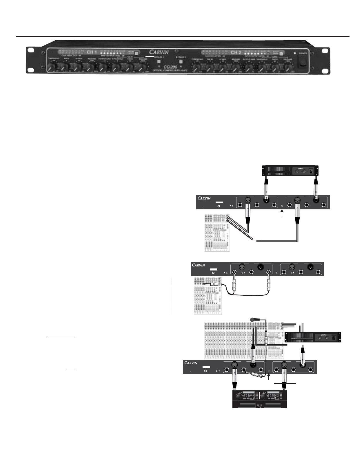
CONNECTING UP
The CG200 can be used in various applications that require different
configuration within a sound system. Fig. 1 shows the CG200
connected between the stereo output of a mixer and the inputs of a
power amp. This is best for compressing or gating an entire main
mix of program material. Fig. 2 depicts a channel insert
connection. This is done with a TRS (tip send, ring return) Y-cable.
The signal is sent out of the channel, compressed/gated and
returned into the channel. This is a typical set-up on most vocal or
drum microphone channels. Fig. 3 depicts a mic channel direct out
to the SIDE CHAIN INPUT. The mic signal triggers the
compressor/gate .
GND
LIFT
1-800-854-2235
www.carvin.com
MADE
AUS
IN THE
CG200
OPTICAL COMPRESSOR/GATE
SERIAL NUMBER
90-250 VAC
INTERNAL FUSE
10 VA 50-60Hz
STEREO
LINK
INPUTS OUTPUTS
SIDE CHAIN
INPUT
0 dBu
+6 dBu
0 dBu
+6 dBu
UNBAL UNBAL
UNBAL
CH1
INPUTS OUTPUTS
SIDE CHAIN
INPUT
UNBAL UNBAL
CH2
PROTECT
∞
5050
3030
2222
1919
1717
1515
1313
1212
1111
1010
9
8
7
6
5
4
3
2
1
0 dB0 dB
DCM1000
1000 Watt Power Amp
CLIP
SIGNAL
∞
5050
3030
2222
1919
1717
1515
1313
1212
1111
1010
9
8
7
6
5
4
3
2
1
0 dB0 dB
POWER
CHANNEL ONE CHANNEL TWO
CLIP
SIGNAL
POWER AMP
L-R OUTPUT
GND
LIFT
1-800-854-2235
www.carvin.com
MADE
AUS
IN THE
CG200
OPTICAL COMPRESSOR/GATE
SERIAL NUMBER
90-250 VAC
INTERNAL FUSE
10 VA 50-60Hz
STEREO
LINK
INPUTS OUTPUTS
SIDE CHAIN
INPUT
0 dBu
+6 dBu
0 dBu
+6 dBu
UNBAL UNBAL
UNBAL
CH1
INPUTS OUTPUTS
SIDE CHAIN
INPUT
UNBAL UNBAL
CH2
∞
50
30
22
19
17
15
13
12
11
10
9
8
7
6
5
4
3
2
1
0 dB
∞
50
30
22
19
17
15
13
12
11
10
9
8
7
6
5
4
3
2
1
0 dB
∞
50
30
22
19
17
15
13
12
11
10
9
8
7
6
5
4
3
2
1
0 dB
∞
50
30
22
19
17
15
13
12
11
10
9
8
7
6
5
4
3
2
1
0 dB
GND
LIFT
1-800-854-2235
www.carvin.com
MADE
AUS
IN THE
CG200
OPTICAL COMPRESSOR/GATE
SERIAL NUMBER
90-250 VAC
INTERNAL FUSE
10 VA 50-60Hz
STEREO
LINK
INPUTS OUTPUTS
SIDE CHAIN
INPUT
0 dBu
+6 dBu
0 dBu
+6 dBu
UNBAL UNBAL
UNBAL
CH1
INPUTS OUTPUTS
SIDE CHAIN
INPUT
UNBAL UNBAL
CH2
PROTECT
∞
5050
3030
2222
1919
1717
1515
1313
1212
1111
1010
9
8
7
6
5
4
3
2
1
0 dB0 dB
DCM1000
1000 Watt Power Amp
CLIP
SIGNAL
∞
5050
3030
2222
1919
1717
1515
1313
1212
1111
1010
9
8
7
6
5
4
3
2
1
0 dB0 dB
POWER
CHANNEL ONE CHANNEL TWO
CLIP
SIGNAL
POWER AMP
L-R OUTPUT
OPEN/CLOSE
CD 1
DUAL CD PLAYER
OPEN/CLOSE
REV FWD
PITCH CONTROL
8%,12%,16%
-SEAMLESS LOOP-
PLAY/PAUSE
TRACK SKIP
RELAY
SHUTTLEJOG
CD1
0
+
-
CD 2
OPEN/CLOSE
REV FWD
PITCH CONTROL
8%,12%,16%
-SEAMLESS LOOP-
PLAY/PAUSE
TRACK SKIP
RELAY
SHUTTLEJOG
CD1
0
+
-
CD Player
Enable the STEREO
LINK switch so both
channels are controlled
by the settings on
Channel 1.
FIG. 1
FIG. 2
FIG. 3
Enable the STEREO
LINK switch so both
channels are controlled
by the settings on
Channel 1.
Connect the CG200 between the CD
player and the mixer. Use a
standard unbalanced 1/4” cable and
“half insert” into the INSERT jack on
the mixer and connect the other end
to the SIDE CHAIN INPUT on the
CG200. Connect a vocal mic to the
same channel as the insert cable on
the mixer. The CG200 will
compress the CD audio whenever
someone speaks into the mic.
c
FREQUENCY RESPONSE: 20Hz TO 20kHz +/- 1dB
DYNAMIC RANGE: 115dB
MAX INPUT LEVEL: +20dBu
THD+N: LESS THAN 0.002% 20Hz TO 20kHz,
NO COMPRESSION/GATING, 0dB INPUT
LESS THAN 0.05%, ANY AMOUNT OF
COMPRESSION, 0dB INPUT
ATTACK AND RELEASE TIMES NOMINAL
INPUT IMPEDANCE: 20K BALANCED XLR
CROSSTALK: <-90dB 20Hz TO 20kHz
OUTPUT GAIN: -∞ TO +12dB
COMPRESSOR
THRESHOLD RANGE: -30bB to +20dB
RATIO: 2:1 TO 20:1
ATTACK TIME: 4mS TO 400mS
RELEASE TIME: 10mS TO 2 SEC
GATE
THRESHOLD RANGE: OFF(OPEN GATE) TO +10dB
RATIO: 1:1(OFF) TO 30:1
RELEASE TIME: 1mS TO 2 SEC
INPUTS AND OUTPUTS: XLR BALANCED AND 1/4” UNBALANCED
SIDECHAIN INPUT: 1/4” UNBALANCED
INPUT LEVEL SELECTION: 0dBu or +6dBu
POWER REQUIREMENTS: 4VA 90-250VAC, 50/60Hz SWITCHING SUPPLY
FUSE: INTERNAL 1.5A FAST BLOW
DIMENSIONS: 1 3/4”H x 19”W x 6”D
SHIPPING WEIGHT: 7 LBS
CG200 SPECIFICATIONS
Page 2

1. GAIN REDUCTION LED METER
Shows how much gain reduction (in dB) that is taking place
whether compression, gating or both.
2. INPUT/OUTPUT LED METER
Shows the incoming signal or output signal level (in dB) depending
on the position of the meter in/out switch.
3. METER IN/OUT SWITCH
When this switch is “IN”, the input/output meter shows the input
signal level. When “OUT”, the meter shows output level.
4. BYPASS SWITCH
With this switch “IN”, the signal passes with no processing. Note:
The OUTPUT GAIN knob will still control the output level even when
the CG200 is set to bypass.
5. BYPASS INDICATOR
This LED illuminates when the unit is bypassed.
6. POWER INDICATOR
This LED illuminates when power to the unit is on.
7. POWER SWITCH
Push this switch to the "ON" position to apply power to the unit. The
power indicator LED will light to show the CG200 is on.
8. THRESHOLD
The THRESHOLD is the signal level where compression begins. All
incoming signals above this threshold will be compressed
according to the RATIO control. If no compression is desired, and
use of the gate is desired by itself, turn the THRESHOLD control
clockwise to "OFF"
9. RATIO:
The RATIOis the amount of compression applied to the signal above
the threshold setting. The numbers 2 through 20 are the dB of input
signal required to achieve a 1 dB output increase. 2:1 is the most
subtle. 20:1 is the most extreme and will produce a more
"squashed" sound. High ratio settings can be used for limiting.
10. ATTACK:
Delay (in milliseconds) is “before compression takes place.” A
short attack time will respond much faster to signal dynamics than
a longer setting. Increase this setting if you want the initial hit
from a snare or punch from a bass to get through before
compressing the signal.
11. RELEASE:
Time (in milliseconds) in which compression is held after the
initial attack. The shorter the release time, the closer the
compressor follows the signal dynamics. Longer release times will
tend to make the sound more "squashed".
12. OUTPUT GAIN:
Output signal level. Use this after setting the compressor to make
up the over all signal level lost due to compression.
13. GATE THRESHOLD:
Signal level where “gating begins.” All incoming signals below this
threshold will be attenuated according to the GATE RATIO control.
Any signals above this threshold will be passed unaffected (unless
compression is on). If no gating is desired, turn this control fully
counter clockwise to the "OFF" position.
14. GATE RATIO:
Amount of attenuation applied to the signal below the gate
threshold level. Setting the GATE RATIO to 1:1 will effectively turn
gating off. A setting of 30:1 will attenuate all incoming signals
below the gate threshold by 30dB.
15. GATE RELEASE:
Amount of time after signal reaches the Gate Threshold before
gating turns on. The shorter the setting, the more "choppy" and
tighter the effect. The longer the time, the smoother the effect but
the more un-wanted noise will pass.
1
3
2
4
5
7
6
FRONT PANEL:
8
9
10
11
12
13
14
15
COMPRESS A STEREO MIX
CONNECTION METHOD: STEREO L-R MIX (see fig. 1)
To compress a stereo mix, depress the STEREO LINK button. Start with a
low RATIO setting. Set the THRESHOLD for a bit of Gain Reduction and
set the ATTACK on a slow setting. Raise the RATIOfor more compression
if needed.
EVEN OUT VARIOUS VOCAL MICS
CONNECTION METHOD: CHANNEL INSERT (see fig. 2)
In a situation where there are various vocalists with different dynamics, it
is best to compress each mic channel before adding each mic to the mix.
Start with a medium ATTACK setting on each mic. Set the RELEASE time
to a slow setting. Set the compression RATIO to 4:1. Set the
THRESHOLD so the GAIN REDUCTION meters show 9dB of gain
reduction. Increase the compression RATIO as needed. Soft vocal signals
may require a higher RATIO setting.
BASS GUITAR, ELECTRIC GUITAR COMPRESSION
CONNECTION METHOD: CHANNEL INSERT (see fig. 2)
To increase Bass sustain and reduce transient spikes, set the
compression RATIO around 4:1, set the THRESHOLD at 9dB of gain
reduction. Use a higher RATIO setting (5:1 or higher) to add sustain to
Guitar signals. Set the THRESHOLD as needed.
Compressor/Gate Applications
Page 3

16. LINE CORD:
The exclusive built-in auto switching power supply allows you to
connect any voltage from 90 to 255v 50-60Hx. Use a 3-conductor
line cord for maximum safety. If the CG200 is to be plugged into a
2-prong outlet, use a quality 3-to-2 prong grounded adapter. Do
not defeat the grounding pin of your AC line cord.
17. GROUND LIFT SWITCH:
This switch lifts the grounds on the inputs and outputs when
depressed. Useful in getting rid of ground loops.
18. UNBALANCED 1/4" INPUT:
This input will accept an unbalanced input from insert patch
cables, amplifier effects sends, etc. The tip is signal, the ring is
shield.
19. LEVEL SWITCH:
Depressing this switch “OUT” gives a 6 dBu boost to the input
signal if a low level signal is to be used.
20. BALANCED XLR INPUT:
This input will increase the gain by 3dB because it is balanced and
that will be most resistant to any induced noise. The connector
wiring is: Pin 1 – ground, Pin 2 – Positive Balance, Pin 3 –
Negative Balance.
21. SIDE CHAIN INPUT:
Use this if an external source is desired to control the compressor
or gate (ducking, de-essing, etc.). For example, if a lower music
level were desired when someone is talking on a microphone, the
microphone signal would be split, and sent into the side-chain
input. The music would be run into the input and back out of the
output of the processor. The music would automatically be turned
down when ever some one spoke into the mic, according to the
compressor settings. The Tip is signal, Ring is shield.
22. BALANCED XLR OUTPUT:
The balanced output is also 3dB hotter out the 1/4” output
because thats what “active balancing” does to the signal. for the
processor. The connector wiring is the same as for the balanced
XLR input.
23. UNBALANCED 1/4" OUTPUT:
This is the unbalanced output for the processor. Use this to return
the processed signal to insert patch cables, or the return on an
amplifier effects loop. The tip is signal, ring is shield.
24. STEREO LINK:
Depressing this switch links channel 2 to channel 1 for stereo
operation. The controls for channel 1 become the master controls
for both channels, with the exception of the Output Level controls
and Level switch, which remain independent. The signals are
effectively processed identically in this mode to give proper stereo
imaging.
REAR PANEL:
16
17
18
19
20
21
22
23
24
COMPRESSING DRUMS
CONNECTION METHOD: CHANNEL INSERT (see fig. 2)
To tighten the sound of a kick drum start with a RATIO around 6:1. Turn
up the THRESHOLD until the GAIN REDUCTION LED’s light up around
12dB. Increase the compression RATIO if needed. These suggested
settings can also be a starting point for snare and tom-toms. Experiment
for the best results.
To gate a drum mic signal so adjacent sounds don’t “false trigger” the
gate, set a fast RELEASE time so the gate closes fairly quick after the
signal falls under the THRESHOLD. This will help tighten up the sound of
a drum kit by eliminating sustained “ring”.
DISTORTION PREVENTION-SPEAKER PROTECTION
CONNECTION METHOD: STEREO L-R MIX (see fig. 1)
A compressor can be used to control audio levels from distorting power
amps and speakers. If the audio mix being sent to the power amps is
loud, a 10:1 or more RATIO setting with the THRESHOLD provide 15dB or
more of compression, which will protect against surprise signal spikes.
For best results in this application, position the compressor before any
EQ’s in the system.
INPUT
OUTPUT
THRESHOLD
RATIO 20:1
RATIO 2:1
CG200 COMPRESSION CURVE
Page 4

CAUTION
RISK OF ELECTRIC SHOCK
DO NOT OPEN
SAFETY INSTRUCTIONS (EUROPEAN)
The conductors in the AC power cord are colored in accordance with the following code.
GREEN & YELLOW—Earth BLUE—Neutral BROWN—Live
U.K. MAIN PLUG WARNING: A molded main plug that has been cut off from the cord is unsafe. NEVER
UNDER ANY CIRCUMSTANCES SHOULD YOU INSERT A DAMAGED OR CUT MAIN PLUG INTO A POWER SOCKET.
IMPORTANT! FOR YOUR PROTECTION, PLEASE READ THE FOLLOWING:
WATER AND MOISTURE: Appliance should not be used near water (near a bathtub, washbowl,
kitchen sink, laundry tub, in a wet basement, or near a swimming pool, etc). Care should be taken
so that objects do not fall and liquids are not spilled into the enclosure through openings.
POWER SOURCES: The appliance should be connected to a power supply only of the type
described in the operating instructions or as marked on the appliance.
GROUNDING OR POLARIZATION: Precautions should be taken so that the grounding or
polarization means of an appliance is not defeated.
POWER CORD PROTECTION: Power supply cords should be routed so that they are not likely to
be walked on or pinched by items placed upon or against them, paying particular attention to
cords at plugs, convenience receptacles, and the point where they exit from the appliance.
SERVICING: The user should not attempt to service the appliance beyond that described in the
operating instructions. All other servicing should be referred to qualified service personnel.
FUSING: If your unit is equipped with a fuse receptacle, replace only with the same type fuse.
Refer to replacement text on the unit for correct fuse type.
REFER SERVICING TO QUALIFIED SERVICE PERSONNEL!
This symbol is intended to alert the user to
the presence of uninsulated “dangerous
voltage” within the product’s enclosure that
may be of sufficient magnitude to
constitute a risk of electric shock to persons.
This symbol is intended to alert the
user to the presence of important
operating and maintenance
(servicing) instructions in the
literature accompanying the appliance.
LIMITED WARRANTY
Your Carvin product is guaranteed against failure for 1 YEAR unless otherwise stated. Carvin
will service and supply all parts at no charge to the customer providing the unit is under
warranty. Shipping costs are the responsibility of the customer. CARVIN DOES NOT PAY FOR
PARTS OR SERVICING OTHER THAN OUR OWN. A COPY OF THE ORIGINAL INVOICE IS
REQUIRED TO VERIFY YOUR WARRANTY. Carvin assumes no responsibility for horn drivers or
speakers damaged by this unit. This warranty does not cover, and no liability is assumed, for
damage due to: natural disasters, accidents, abuse, loss of parts, lack of reasonable care,
incorrect use, or failure to follow instructions. This warranty is in lieu of all other warranties,
expressed or implied. No representative or person is authorized to represent or assume for
Carvin any liability in connection with the sale or servicing of Carvin products.
CARVIN SHALL
NOT BE LIABLE FOR INCIDENTAL OR CONSEQUENTIAL DAMAGES.
When RETURNING merchandise to the factory, you may call for a return authorization
number. Describe in writing each problem. If your unit is out of warranty, you will be charged
the current FLAT RATE for parts and labor to bring your unit up to factory specifications.
MAINTAINING YOUR EQUIPMENT
Avoid spilling liquids or allowing any other foreign matter inside the unit. The panel of
your unit can be wiped from time to time with a dry or slightly damp cloth in order to
remove dust and bring back the new look.
As with all pro gear, avoid prolonged use in
caustic environments (salt air). When used in such an environment, be sure the mixer is
adequately protected by a cover.
CG200 PARTS LIST
03-50250 3 EACH STANDOFF LED .250 X .135 T1
“FOR D3, D17, D217”
03-92521 32 EACH STANDOFF LED .925 x .215 T1
“FOR D1, D2, D4, D6, D7, D8, D9,”
“D10, D12, D13, D14, D15, D18,”
“D21, D5, D22, D201, D202, D204,”
“D205, D206, D207, D208, D209, D210,”
“D212, D213, D214, D215, D218, D221,”
D222
06-40040 2 EACH TERMINAL VERT FEML PC MTG .250
S10
07-01603 4 EACH “KNOB “”6L”” 6x6x17.4mm GREY CAP”
“FOR S3, S4, S5, S205”
15-00300 2 EACH INDUCTOR .3 mH DRUM CORE
“L8, L10”
15-05002 2 EACH LINE FILTER 5mh ASE-1303F B
L3
15-10110 2 EACH INDUCTOR CHOKE 100uH 1.13Amp
“L1, L2”
15-86020G 1 EACH XFORM SWITCHING 20W .3/.6AMP
T1
21-40000 2 EACH XLR FEMALE CONNECTOR W/O GRND
“J5, J205”
21-40001 2 EACH XLR MALE CONNECTOR
“J4, J204”
21-31100 1 EACH RECEPTACLE AC W/FAST-ON CHASS
PL1
21-51345 6 EACH JACK .250 PHONE MONO PLASTIC
“J1, J2, J3, J201, J202, J203”
23-05601 2 EACH FUSE HOLDER BRASS .5 mm
F1
23-10308B 1 EACH “HEADER 8 PIN SIP 1.015”””
H2B
23-11004 6 EACH CONNECT HEADER 4 PIN STRAIGHT
“H3A, H4A, H4B, H5A, H5B, H201A”
23-11008 1 EACH CONNECT HEADER 8 PIN STRAIGHT
H1A
23-12004 2 EACH CONNECT HEADER 4 PIN RT/ANGLE
“H3B, H201B”
23-12008 1 EACH CONNECT HEADER 8 PIN RT/ANGLE
H1B
23-13008 1 EACH CONNECTOR HEADER 8PIN SIP
H2A
25-02201 3 EACH SWITCH DPDT PUSH PC MTG LOCKNG
“S4, S5, S205”
25-02200- 4 EACH ASSEMBLED SWITCH W/5MM CAP
“S1, S2, S201, S202”
25-04201 1 EACH SWITCH 4PDT PUSH PC MTG LOCKNG
S3
30-02200D 1 EACH PCB C200
REV D
42-33042 1 EACH CAP ELEC 33uF 400VOLT
C106
46-10242 1 EACH CAP POLY .0010UF 400VOLT 10%
C171
41-27322 3 EACH CAP POLY FILM .027uF 250VAC 10
“C338, C339, C341”
41-47422 1 EACH CAP MYLR .47uF 250VAC BOX
C282
41-10342 1 EACH CAP POLY .0100UF 400VOLT 10%
C11
46-47412 2 EACH CAP MYLR .4700UF 63VOLT 10%
“C43, C243”
47-10225 4 EACH “CAP ELEC 1,000 MFD 25V 20%”
“C159, C160, C161, C162”
49-10050 10 EACH CAP SMT 1UF 50V ELECTROLITIC
“C28, C29, C39, C40, C42, C228,”
“C229, C239, C240, C242”
49-10312 3 EACH 0.01UF SMT 10% FILM 080550V
“C47, C167, C168”
49-10412 4 EACH 0.1UF SMT +80-20% CERAMIC 0805
“C25, C26, C225, C226”
49-18152 10 EACH 180PF SMT 5% CERAMIC 0805
“C15, C18, C27, C33, C212, C215, C218”
“C227, C233, C12”
49-22035 21 EACH SMT CAP 22uF 35v ELECTROLITIC
“C3, C8, C10, C13, C16, C19, C20, C22”
“C23, C24, C32, C166, C203, C208, C210,”
“C213, C216, C219, C220, C224, C232”
49-27052 4 EACH 27 PF SMT 5% CERAMIC 0805
“C30, C31, C230, C231”
49-39052 22 EACH 39PF SMT 5% CERAMIC 0805
“C1, C2, C4, C5, C6, C7, C9, C14, C34,”
“C36, C37, C201, C202, C204, C205, C206,”
“C207, C209, C214, C234, C236, C237”
49-47212 1 EACH 0.0047uF SMT FILM 0805 50V
C158
58-00035 13 EACH 0.0 SMT JUMPER 1206
“R8, R26, R63, R72, R76, R95, R98,”
“R208, R226, R272, R276, R295, R298”
58-10025 17 EACH 100.5 SMT .25W 1206 1%
“R5, R7, R16, R25, R64, R87, R108,”
“R109, R118, R205, R207, R216, R225,”
“R287, R2108, R2109, R2118”
58-10035 8 EACH 1K SMT .25W 1206 1%
“R55, R57, R100, R103, R255, R257,
R2100, R2103”
58-10045 47 EACH 10K SMT .25W 1206 1%
“R1, R3, R4, R15, R18, R20, R34, R46, R47,”
“R59, R60, R61, R62, R66, R67, R71, R73,”
“R77, R78, R79, R111, R112, R114,”
“R116, R201, R203, R204, R215, R218,”
“R220, R234, R246, R247, R259, R261,”
“R262, R266, R267, R271, R273, R277,”
“R278, R279, R2111, R2112, R2114, R2116”
58-10055 10 EACH 100K SMT .25W 1206 1%
“R10, R14, R28, R93, R113, R210, R214,”
“R228, R293, R2113”
58-10065 2 EACH 1M SMT .25W 1206 1%
“R88, R288”
58-15035 2 EACH 1.5K SMT .25W 1206 1%
“R80, R280”
58-15045 6 EACH 15K SMT .25W 1206 1%
“R27, R32, R58, R227, R232, R258”
58-15055 2 EACH 150K SMT .25W 1206 1%
“R102, R2102”
58-18035 4 EACH 1.8K SMT .25W 1206 1%
“R45, R50, R245, R250”
58-22015 2 EACH 22.1 SMT .25W 1206 1%
“R86, R286”
58-22025 2 EACH 220.5 SMT .25W 1206 1%
“R9, R209”
58-22035 13 EACH 2.2K SMT .25W 1206 1%
“R11, R21, R43, R44, R99, R101, R107, R211,”
“R221, R243, R244, R299, R2101”
58-22045 16 EACH 22K SMT .25W 1206 1%
“R2, R12, R19, R30, R56, R68, R69,”
“R74, R94, R202, R219, R256, R268,
R269,”
“R274, R294”
58-22055 2 EACH 220K SMT .25W 1206 1%
“R65, R265”
58-27045 2 EACH 27K SMT .25W 1206 1%
“R38, R238”
58-33035 8 EACH 3.3K SMT .25W 1206 1%
“R24, R41, R42, R49, R224, R241, R242 , R249”
58-39035 1 EACH 3.9K SMT .25W 1206 1%
R83
58-43045 2 EACH 43K SMT .25W 1206 1%
“R35, R235”
58-47025 4 EACH 470.5 SMT .25W 1206 1%
“R53, R54, R253, R254”
58-47035 7 EACH 4.7K SMT .25W 1206 1%
“R17, R22, R40, R106, R240, R217, R216”
58-47045 12 EACH 47K SMT .25W 1206 1%
“R6, R48, R81, R104, R105, R206, R115,
R248, R281,”
“R2104, R2105, R2115”
58-47055 4 EACH 470K SMT .25W 1206 1%
“R70, R117, R270, R2117”
58-56035 1 EACH 5.6K SMT .25W 1206 1%
R85
58-68015 9 EACH 68.5 SMT .25W 1206 1%
“R23, R33, R51, R84, R97, R223,”
“R233, R251, R297”
58-68035 4 EACH 6.8K SMT .25W 1206 1%
“R36, R82, R236, R282”
58-68045 6 EACH 68K SMT .25W 1206 1%
“R29, R37, R39, R229, R237, R239”
58-91025 2 EACH 910.5 SMT .25W 1206 1%
“R52, R252”
60-20060 1 EACH TRANSIENT VOLT SUPP 200V 600W
Z1
60-22020 1 EACH IC PRIMARY VIPER 20 8P DIP
VP1
60-25011 1 EACH IC OPTO COUPLER ISOLATOR
OP3
60-40002 1 EACH THERMISTOR 40ohm 2amp 20%
TR1
60-50253-1 6 EACH OPTO ISOLATOR VACTROL AXL TEST
“OP1, OP2, OP3, OP201, OP202, OP203”
60-75320 22 EACH LED RED DIFFUSED 3MM T-1.00
“D1, D4, D6, D7, D8, D9, D10,”
“D17, D18, D21, D23, D201, D204, D206,”
“D207, D208, D209, D210, D217,”
“D218, D221, D223”
60-75330 11 EACH LED GREEN DIFFUSED 3MM T-1.00
“D3, D5, D12, D13, D14, D15, D205,”
“D212, D213, D214, D215”
60-75340 4 EACH LED YELLOW DIFFUSED 3MM T-1.00
“D2, D22, D202, D222”
61-47450 1 EACH DIODE ZNR REG 1N4745A 16V 1W
Z2
62-06001 7 EACH DIODE ULTRA FAST 600V 1A SMA
“D25, D26, D27, D31, D32, D33, D34”
62-19140 9 EACH 1N914 HI SPD SMT 250mW DIODE
“D11, D16, D19, D20, D24, D28, D219, D220,
D224”
62-20430 6 EACH NJM2043SMT(TESTED) DUAL HFREQ
“A1, A2, A11, A201, A202, A211”
62-29010 12 EACH NJM2901SMT QUAD COMP
“A5, A6, A7, A8, A10, A12, A204,”
“A205, A206, A207, A208, A212”
62-45650 8 EACH NJM4565 SMT DUAL HI FREQ
“A3, A4, A9, A13, A17, A203, A209, A213”
62-54001 10 EACH MMBT5401LT1 PNP SOT-23 SMT
“Q1, Q2, Q4, Q5, Q7, Q201, Q202, Q204,”
“Q205, Q207”
62-55500 2 EACH MMBT5550 NPN SOT-23
“Q3, Q203”
70-12015 1 EACH FUSE 320 1.50A SLOW 5X 20MM
F1
71-09012 2 EACH POT 9 D-P 25F 10K THREAD
“P2, P202”
71-09210B 2 EACH “POT 9 “”D-P”” 25F 10C10K BLACK”
“P4, P204”
71-09250 2 EACH POT 9 D-P 25F B50K THREAD BLK
“P7, P207”
71-09251A 2 EACH POT 9 D-P 25F B10K THREAD LTGR
“P1, P201”
71-09500 8 EACH POT 9 D-P 25F 500K THREAD
“P3, P5, P8, P9, P203, P205, P208, P209”
71-24450 2 EACH POT VERT TRIMMER 500ohm
“P11, P211”
 Loading...