

Page 1

CAUTION
RISK OF ELECTRIC SHOCK
DO NOT OPEN
SAFETY INSTRUCTIONS (EUROPEAN)
The conductors in the AC power cord are colored in accordance with the following code.
GREEN & YELLOW—Earth BLUE—Neutral BROWN—Live
U.K. MAIN PLUG WARNING: Amolded main plug that has been cut off from the cord is unsafe. NEVER
UNDER ANY CIRCUMSTANCES SHOULD YOU INSERT ADAMAGED OR CUT MAIN PLUG INTO A POWER SOCKET.
IMPORTANT! FOR YOUR PROTECTION, PLEASE READ THE FOLLOWING:
WATER AND MOISTURE: Appliance should not be used near water (near a bathtub, washbowl, kitchen
sink, laundry tub, in a wet basement, or near a swimming pool, etc). Care should be taken so that
objects do not fall and liquids are not spilled into the enclosure through openings.
POWER SOURCES: The appliance should be connected to a power supply only of the type described
in the operating instructions or as marked on the appliance.
GROUNDING OR POLARIZATION: Precautions should be taken so that the grounding or polarization means of an appliance is not defeated.
POWER CORD PROTECTION: Power supply cords should be routed so that they are not likely to
be walked on or pinched by items placed upon or against them, paying particular attention to cords
at plugs, convenience receptacles, and the point where they exit from the appliance.
SERVICING: The user should not attempt to service the appliance beyond that described in the
operating instructions. All other servicing should be referred to qualified service personnel.
FUSING: If your unit is equipped with a fuse receptacle, replace only with the same type fuse. Refer
to replacement text on the unit for correct fuse type.
REFER SERVICING TO QUALIFIED SERVICE PERSONNEL!
REF. Carvin P/N Description
Channel PCB Rev (C) 30-08248
A1 60-20430 Op Amp NJM2043D Linear Dual
A2 60-45580 Op Amp MC4558 CP1 Dual HFREQ
A3 60-45580 Op Amp MC4558 CP1 Dual HFREQ
A4 60-45580 Op Amp MC4558 CP1 Dual HFREQ
A5 60-20430 Op Amp NJM2043D Linear Dual
B1 50-00035 Jumper .35" 0.0Ω
B2 50-00035 Jumper .35" 0.0Ω
B3 50-00035 Jumper .35" 0.0Ω
B4 50-00035 Jumper .35" 0.0Ω
B5 50-00035 Jumper .35" 0.0Ω
B10 50-47005 1/4W Resistor 4.7K 5% Carbon
B12 50-00035 Jumper .35" 0.0Ω
B13 50-00035 Jumper .35" 0.0Ω
B14 50-00035 Jumper .35" 0.0Ω
B15 50-00035 Jumper .35" 0.0Ω
B16 50-00035 Jumper .35" 0.0Ω
B17 50-00035 Jumper .35" 0.0Ω
B18 50-00035 Jumper .35" 0.0Ω
B21 50-00035 Jumper .35" 0.0Ω
B22 50-00035 Jumper .35" 0.0Ω
B23 50-00035 Jumper .35" 0.0Ω
B24 50-00035 Jumper .35" 0.0Ω
B31 50-00035 Jumper .35" 0.0Ω
B32 50-00035 Jumper .35" 0.0Ω
B33 50-00035 Jumper .35" 0.0Ω
B34 50-00035 Jumper .35" 0.0Ω
B41 50-00035 Jumper .35" 0.0Ω
B42 50-00035 Jumper .35" 0.0Ω
B43 50-00035 Jumper .35" 0.0Ω
B44 50-00035 Jumper .35" 0.0Ω
B51 50-00035 Jumper .35" 0.0Ω
B52 50-00035 Jumper .35" 0.0Ω
B53 50-00035 Jumper .35" 0.0Ω
B54 50-00035 Jumper .35" 0.0Ω
B55 50-00035 Jumper .35" 0.0Ω
B61 50-00035 Jumper .35" 0.0Ω
B62 50-00035 Jumper .35" 0.0Ω
B63 50-00035 Jumper .35" 0.0Ω
B64 50-00035 Jumper .35" 0.0Ω
B71 50-00035 Jumper .35" 0.0Ω
B72 50-00035 Jumper .35" 0.0Ω
B73 50-00035 Jumper .35" 0.0Ω
B74 50-00035 Jumper .35" 0.0Ω
B81 50-00035 Jumper .35" 0.0Ω
B82 50-00035 Jumper .35" 0.0Ω
B83 50-00035 Jumper .35" 0.0Ω
B84 50-00035 Jumper .35" 0.0Ω
C1 45-39052 Capacitor 39PF 500 Volt Ceramic 5%
C2 45-39052 Capacitor 39PF 500 Volt Ceramic 5%
C3 47-22051 Capacitor 22µF 50V Electrolytic 20%
C4 47-22051 Capacitor 22µF 50V Electrolytic 20%
C5 46-47312 Capacitor 0.047µF 100V Poly 10%
C6 47-22051 Capacitor 22µF 50V Electrolytic 20%
C7 45-39052 Capacitor 39PF 500 Volt Ceramic 5%
C8 46-47312 Capacitor 0.047µF 100V Poly 10%
C9 46-33312 Capacitor 0.033µF 100V Poly 10%
C10 47-22051 Capacitor 22µF 50V Electrolytic 20%
C11 45-39052 Capacitor 39PF 500 Volt Ceramic 5%
C12 45-39052 Capacitor 39PF 500 Volt Ceramic 5%
C13 47-22051 Capacitor 22µF 50V Electrolytic 20%
C14 47-22051 Capacitor 22µF 50V Electrolytic 20%
C15 47-22051 Capacitor 22µF 50V Electrolytic 20%
C16 46-10312 Capacitor 0.01µF 100V Poly 10%
C17 47-22051 Capacitor 22µF 50V Electrolytic 20%
C18 47-47116 Capacitor 470µF 16V Electrolytic 20%
C19 47-47116 Capacitor 470µF 16V Electrolytic 20%
C20 45-39052 Capacitor 39PF 500 Volt Ceramic 5%
C21 45-56152 Capacitor 560PF 500V Ceramic 10%
C22 45-56152 Capacitor 560PF 500V Ceramic 10%
C23 46-33212 Capacitor 0.0033µF 100V Poly 10%
C24 47-22051 Capacitor 22µF 50V Electrolytic 20%
D1 60-75330 LED Green small #204GD 3mm T-1.0
D2 60-75320 LED Red small #204HD 3mm T-1.0
D10 60-75320 LED Red small #204HD 3mm T-1.0
H1 23-11008 Header 8 Pin Vert SHS 2.5mm
H2 23-11008 Header 8 Pin Vert SHS 2.5mm
H3 23-11008 Header 8 Pin Vert SHS 2.5mm
H11 23-11008 Header 8 Pin Vert SHS 2.5mm
H12 23-11008 Header 8 Pin Vert SHS 2.5mm
H13 23-11008 Header 8 Pin Vert SHS 2.5mm
J1 21-50545 Phone Jack 1/4" 5 pin H= 24mm
J2 21-40000 XLR Jack Female Vert
J3 21-50545 Phone Jack 1/4" 5 pin H= 24mm
P1 71-09253 Potentiometer B50K Vert D Shaft 9 25F
P2 71-09252 Potentiometer B50K C-C D Shaft 9 25F
P3 71-09252 Potentiometer B50K C-C D Shaft 9 25F
P4 71-09252 Potentiometer B50K C-C D Shaft 9 25F
P5 71-09253 Potentiometer B50K D Shaft 9 25F
P6 71-09253 Potentiometer B50K Vert D Shaft 9 25F
P7 71-09253 Potentiometer B50K Vert D Shaft 9 25F
P8 71-09253 Potentiometer B50K Vert D Shaft 9 25F
P9 72-13169 Potentiometer B50Kx2 C-C D 14 25F
P10 71-15065 Fader 25A50K 60mm HT= .215mm
R1 50-56231 1/4W Resistor 5.62 1% Metal
R2 59-10040 1/8W Resistor 10K x4 SIP 2% Carbon
R3 50-10045 1/4W Resistor 10K 5% Carbon
R4 50-15031 1/4W Resistor 1.51K 1% Metal
R5 50-15031 1/4W Resistor 1.51K 1% Metal
R6 50-22131 1/4W Resistor 2.21K 1% Metal
R7 59-10040 1/8W Resistor 10K x4 SIP 2% Carbon
R8 50-47025 1/4W Resistor 470Ω 5% Carbon
R9 50-68045 1/4W Resistor 68K 5% Carbon
R10 59-10040 1/8W Resistor 10K x4 SIP 2% Carbon
R11 50-10045 1/4W Resistor 10K 5% Carbon
R12 50-10045 1/4W Resistor 10K 5% Carbon
R13 50-22035 1/4W Resistor 2.2K 5% Carbon
R14 50-10025 1/4W Resistor 100Ω 5% Carbon
R15 50-12045 1/4W Resistor 12K 5% Carbon
R16 50-10035 1/4W Resistor 1K 5% Carbon
R17 50-22131 1/4W Resistor 2.21K 1% Metal
R18 50-10025 1/4W Resistor 100Ω 5% Carbon
R19 50-47045 1/4W Resistor 47K 5% Carbon
R20 50-10045 1/4W Resistor 10K 5% Carbon
R21 50-47005 1/4W Resistor 4.7K 5% Carbon
R22 50-10055 1/4W Resistor 100K 5% Carbon
R23 50-56231 1/4W Resistor 5.62 1% Metal
R24 50-47045 1/4W Resistor 47K 5% Carbon
R25 50-47005 1/4W Resistor 4.7K 5% Carbon
R26 50-10025 1/4W Resistor 100Ω 5% Carbon
R27 50-33035 1/4W Resistor 3.3K 5% Carbon
R28 50-47045 1/4W Resistor 47K 5% Carbon
R29 50-33035 1/4W Resistor 3.3K 5% Carbon
R30 50-10045 1/4W Resistor 10K 5% Carbon
R31 50-22045 1/4W Resistor 22K 5% Carbon
R32 50-18045 1/4W Resistor 18K 5% Carbon
R33 50-68035 1/4W Resistor 68K 5% Carbon
R34 50-56035 1/4W Resistor 5.6K 5% Carbon
R35 50-10045 1/4W Resistor 10K 5% Carbon
R36 50-10055 1/4W Resistor 100K 5% Carbon
R37 50-56035 1/4W Resistor 5.6K 5% Carbon
R38 50-47055 1/4W Resistor 470K 5% Carbon
R43 50-56035 1/4W Resistor 5.6K 5% Carbon
R47 50-00035 Jumper .35" 0.0Ω
R100 50-22035 1/4W Resistor 2.2K 5% Carbon
R247 50-00035 Jumper .35" 0.0Ω
R347 50-00035 Jumper .35" 0.0Ω
R447 50-00035 Jumper .35" 0.0Ω
R547 50-00035 Jumper .35" 0.0Ω
R647 50-00035 Jumper .35" 0.0Ω
R747 50-00035 Jumper .35" 0.0Ω
R847 50-00035 Jumper .35" 0.0Ω
S1 25-02201 Switch DPDT Push Vert
S2 25-02201 Switch DPDT Push Vert
S5 25-02201 Switch DPDT Push Vert
S6 25-02201 Switch DPDT Push Vert
S10 25-02201 Switch DPDT Push Vert
Z1 61-04734 Diode Zener 5.6V 1N4734A 1W
System Master PCB Rev (C) 30-16214
A1 60-20430 Op Amp NJM2043D Linear Dual
A10 60-45580 Op Amp MC4560 CP1 Dual HFREQ
A11 60-45580 Op Amp MC4560 CP1 Dual HFREQ
A12 60-45580 Op Amp MC4560 CP1 Dual HFREQ
A13 60-20430 Op Amp NJM2043D Linear Dual
A14 60-20430 Op Amp NJM2043D Linear Dual
A15 60-45580 Op Amp MC4560 CP1 Dual HFREQ
A16 60-45580 Op Amp MC4560 CP1 Dual HFREQ
A19 60-20430 Op Amp NJM2043D Linear Dual
A2 60-20430 Op Amp NJM2043D Linear Dual
A20 60-45580 Op Amp MC4560 CP1 Dual HFREQ
A21 60-45580 Op Amp MC4560 CP1 Dual HFREQ
A22 60-45580 Op Amp MC4560 CP1 Dual HFREQ
A23 60-20430 Op Amp NJM2043D Linear Dual
A24 60-20430 Op Amp NJM2043D Linear Dual
A25 60-45580 Op Amp MC4560 CP1 Dual HFREQ
A26 60-45580 Op Amp MC4560 CP1 Dual HFREQ
A28 60-45580 Op Amp MC4560 CP1 Dual HFREQ
A29 60-20430 Op Amp NJM2043D Linear Dual
A3 60-20430 Op Amp NJM2043D Linear Dual
A30 60-45580 Op Amp MC4560 CP1 Dual HFREQ
A31 60-20430 Op Amp NJM2043D Linear Dual
A32 60-20430 Op Amp NJM2043D Linear Dual
A33 60-20430 Op Amp NJM2043D Linear Dual
A35 60-45580 Op Amp MC4560 CP1 Dual HFREQ
A36 60-20430 Op Amp NJM2043D Linear Dual
A4 60-20430 Op Amp NJM2043D Linear Dual
A41 60-29010 IC DIP 14 Comparitor x4 OC
A42 60-29010 IC DIP 14 Comparitor x4 OC
A43 60-29010 IC DIP 14 Comparitor x4 OC
A44 60-29010 IC DIP 14 Comparitor x4 OC
A45 60-29010 IC DIP 14 Comparitor x4 OC
A5 60-20430 Op Amp NJM2043D Linear Dual
A6 60-45580 Op Amp MC4560 CP1 Dual HFREQ
A7 60-45580 Op Amp MC4560 CP1 Dual HFREQ
A8 60-29010 IC DIP 14 Comparitor x4 OC
C1 45-39052 Capacitor 39PF 500V Ceramic 5%
C10 47-22051 Capacitor 22µF 50V Electrolytic 20%
C100 45-39052 Capacitor 39PF 500V Ceramic 5%
C101 45-39052 Capacitor 39PF 500V Ceramic 5%
C103 47-10061 Capacitor 10µF 63V Electrolytic 20%
C104 47-10061 Capacitor 10µF 63V Electrolytic 20%
C105 48-01031 Capacitor 1µF 35V Tant 10%
C11 45-39052 Capacitor 39PF 500V Ceramic 5%
C116 47-10061 Capacitor 10µF 63V Electrolytic 20%
C118 47-10061 Capacitor 10µF 63V Electrolytic 20%
C119 45-39052 Capacitor 39PF 500V Ceramic 5%
C12 47-10061 Capacitor 10µF 63V Electrolytic 20%
C120 45-39052 Capacitor 39PF 500V Ceramic 5%
C122 47-10061 Capacitor 10µF 63V Electrolytic 20%
C124 47-10061 Capacitor 10µF 63V Electrolytic 20%
C125 45-39052 Capacitor 39PF 500V Ceramic 5%
C126 45-39052 Capacitor 39PF 500V Ceramic 5%
C13 47-22051 Capacitor 22µF 50V Electrolytic 20%
C14 47-22051 Capacitor 22µF 50V Electrolytic 20%
C15 47-10061 Capacitor 10µF 63V Electrolytic 20%
C158 47-10061 Capacitor 10µF 63V Electrolytic 20%
C159 47-10061 Capacitor 10µF 63V Electrolytic 20%
C16 45-39052 Capacitor 39PF 500V Ceramic 5%
C168 45-39052 Capacitor 39PF 500V Ceramic 5%
C169 47-10061 Capacitor 10µF 63V Electrolytic 20%
C17 45-39052 Capacitor 39PF 500V Ceramic 5%
C170 47-10061 Capacitor 10µF 63V Electrolytic 20%
C18 45-39052 Capacitor 39PF 500V Ceramic 5%
C19 46-47312 Capacitor 0.047µF 100V Poly 10%
C2 45-39052 Capacitor 39PF 500V Ceramic 5%
C20 45-82052 Capacitor 82PF 500V Ceramic 5%
C203 47-10061 Capacitor 10µF 63V Electrolytic 20%
C21 45-39052 Capacitor 39PF 500V Ceramic 5%
C22 47-10061 Capacitor 10µF 63V Electrolytic 20%
C23 45-39052 Capacitor 39PF 500V Ceramic 5%
C24 46-10212 Capacitor 0.001µF 100V Poly 10%
C25 45-39052 Capacitor 39PF 500V Ceramic 5%
C26 47-10061 Capacitor 10µF 63V Electrolytic 20%
C27 46-47412 Capacitor 0.47µF 100V Poly 10%
C28 46-22312 Capacitor 0.022µF 100V Poly 10%
C29 46-22461 Capacitor 0.22µF 63V Poly 10%
C3 45-39052 Capacitor 39PF 500V Ceramic 5%
C30 46-68312 Capacitor 0.068µF 100V Poly 10%
C31 46-33212 Capacitor 0.0033µF 100V Poly 10%
C32 46-33312 Capacitor 0.033µF 100V Poly 10%
C33 46-10212 Capacitor 0.001µF 100V Poly 10%
C34 46-22312 Capacitor 0.022µF 100V Poly 10%
C35 45-33113 Capacitor 330PF 1000V 10%
C36 46-10212 Capacitor 0.001µF 100V Poly 10%
C37 45-39052 Capacitor 39PF 500V Ceramic 5%
C38 46-10212 Capacitor 0.001µF 100V Poly 10%
C39 45-39052 Capacitor 39PF 500V Ceramic 5%
C4 45-39052 Capacitor 39PF 500V Ceramic 5%
C40 46-22212 Capacitor 0.0022µF 100V Poly 10%
C41 47-10061 Capacitor 10µF 63V Electrolytic 20%
C42 47-10061 Capacitor 10µF 63V Electrolytic 20%
C43 47-10061 Capacitor 10µF 63V Electrolytic 20%
C44 47-10061 Capacitor 10µF 63V Electrolytic 20%
C45 47-10061 Capacitor 10µF 63V Electrolytic 20%
C46 46-10312 Capacitor 0.01µF 100V Poly 10%
C47 46-10412 Capacitor 0.1µF 100V Poly 10%
C48 46-47212 Capacitor 0.0047µF 100V Poly 10%
C49 45-33113 Capacitor 330PF 1000V 10%
C5 47-10061 Capacitor 10µF 63V Electrolytic 20%
C50 45-39052 Capacitor 39PF 500V Ceramic 5%
C51 46-10212 Capacitor 0.001µF 100V Poly 10%
C52 47-22051 Capacitor 22µF 50V Electrolytic 20%
C53 46-10212 Capacitor 0.001µF 100V Poly 10%
C54 46-10212 Capacitor 0.001µF 100V Poly 10%
C55 46-68212 Capacitor 0.0068µF 100V Poly 10%
C56 46-10212 Capacitor 0.001µF 100V Poly 10%
C57 46-47212 Capacitor 0.0047µF 100V Poly 10%
C58 45-39052 Capacitor 39PF 500V Ceramic 5%
C59 45-39052 Capacitor 39PF 500V Ceramic 5%
C6 45-39052 Capacitor 39PF 500V Ceramic 5%
C60 45-39052 Capacitor 39PF 500V Ceramic 5%
C61 47-10061 Capacitor 10µF 63V Electrolytic 20%
C62 45-25152 Capacitor 250PF 500V Ceramic 5%
C63 45-39052 Capacitor 39PF 500V Ceramic 5%
C64 46-47212 Capacitor 0.0047µF 100V Poly 10%
C65 46-22212 Capacitor 0.0022µF 100V Poly 10%
C66 45-33113 Capacitor 330PF 1000V 10%
C67 45-25152 Capacitor 250PF 500V Ceramic 5%
C68 46-10212 Capacitor 0.001µF 100V Poly 10%
C69 45-33113 Capacitor 330PF 1000V 10%
C7 47-10061 Capacitor 10µF 63V Electrolytic 20%
C70 47-47125 Capacitor 470µF 25V Electrolytic 20%
C71 47-10061 Capacitor 10µF 63V Electrolytic 20%
C72 45-39052 Capacitor 39PF 500V Ceramic 5%
C73 46-47412 Capacitor 0.47µF 100V Poly 10%
C74 46-22312 Capacitor 0.022µF 100V Poly 10%
C75 46-22461 Capacitor 0.22µF 63V Poly 10%
C76 46-10312 Capacitor 0.01µF 100V Poly 10%
C77 46-10412 Capacitor 0.1µF 100V Poly 10%
C78 46-47212 Capacitor 0.0047µF 100V Poly 10%
C79 46-68312 Capacitor 0.068µF 100V Poly 10%
C8 45-39052 Capacitor 39PF 500V Ceramic 5%
C80 46-33212 Capacitor 0.0033µF 100V Poly 10%
C81 46-33312 Capacitor 0.033µF 100V Poly 10%
C82 46-10212 Capacitor 0.001µF 100V Poly 10%
C83 46-22312 Capacitor 0.022µF 100V Poly 10%
C84 46-10212 Capacitor 0.001µF 100V Poly 10%
C85 46-68212 Capacitor 0.0068µF 100V Poly 10%
C86 45-33113 Capacitor 330PF 1000V 10%
C87 45-39052 Capacitor 39PF 500V Ceramic 5%
C88 46-10212 Capacitor 0.001µF 100V Poly 10%
C89 47-22051 Capacitor 22µF 50V Electrolytic 20%
C9 47-10061 Capacitor 10µF 63V Electrolytic 20%
C90 47-47125 Capacitor 470µF 25V Electrolytic 20%
C91 46-47312 Capacitor 0.047µF 100V Poly 10%
C92 46-47312 Capacitor 0.047µF 100V Poly 10%
C93 45-82052 Capacitor 82PF 500V Ceramic 5%
C94 45-82052 Capacitor 82PF 500V Ceramic 5%
C95 45-82052 Capacitor 82PF 500V Ceramic 5%
C96 45-82052 Capacitor 82PF 500V Ceramic 5%
C97 45-39052 Capacitor 39PF 500V Ceramic 5%
C98 45-39052 Capacitor 39PF 500V Ceramic 5%
C99 45-39052 Capacitor 39PF 500V Ceramic 5%
D1 60-75320 LED Red small #204HD 3mm T-1.0
D10 60-75340 LED Yellow small #204YD 3mm T-1.0
D11 60-75340 LED Yellow small #204YD 3mm T-1.0
D12 60-75330 LED Green small #204GD 3mm T-1.0
D13 60-75330 LED Green small #204GD 3mm T-1.0
D14 60-75330 LED Green small #204GD 3mm T-1.0
D15 60-75330 LED Green small #204GD 3mm T-1.0
D16 60-75330 LED Green small #204GD 3mm T-1.0
D17 60-75330 LED Green small #204GD 3mm T-1.0
D18 60-75320 LED Red small #204HD 3mm T-1.0
D19 60-75340 LED Yellow small #204YD 3mm T-1.0
D2 61-19140 Diode 1N914 HI SPD 20mA 250mW
D20 60-75340 LED Yellow small #204YD 3mm T-1.0
D21 60-75340 LED Yellow small #204YD 3mm T-1.0
D22 60-75330 LED Green small #204GD 3mm T-1.0
D23 60-75330 LED Green small #204GD 3mm T-1.0
D24 60-75330 LED Green small #204GD 3mm T-1.0
D25 60-75330 LED Green small #204GD 3mm T-1.0
D26 60-75330 LED Green small #204GD 3mm T-1.0
D27 60-75330 LED Green small #204GD 3mm T-1.0
D28 60-75320 LED T-1.750" Lg Red #333HD 5mm
D29 61-19140 Diode 1N914 HI SPD 20mA 250mW
D3 61-19140 Diode 1N914 HI SPD 20mA 250mW
D30 61-19140 Diode 1N914 HI SPD 20mA 250mW
D31 61-19140 Diode 1N914 HI SPD 20mA 250mW
D32 61-19140 Diode 1N914 HI SPD 20mA 250mW
D4 61-19140 Diode 1N914 HI SPD 20mA 250mW
D5 61-19140 Diode 1N914 HI SPD 20mA 250mW
D6 61-19140 Diode 1N914 HI SPD 20mA 250mW
D7 60-75320 LED Red small #204HD 3mm T-1.0
D8 60-75320 LED Red small #204HD 3mm T-1.0
D9 60-75340 LED Yellow small #204YD 3mm T-1.0
E1 25-22203 Rot Encoder Vert 5-bit Vert
H1 23-11008 Header 8 Pin Vert 2.5mm
H2 23-11008 Header 8 Pin Vert 2.5mm
H3 23-11008 Header 8 Pin Vert 2.5mm
H4 23-11008 Header 8 Pin Vert 2.5mm
H5 23-11010 Header 10 Pin Vert 2.5mm
H6 23-11008 Header 8 Pin Vert 2.5mm
J1 21-50545 Phone Jack 1/4" Stereo H=24mm
J10 21-40022 RCA Phono Jack x4
J11 21-50345 Phone Jack 1/4" Mono H=24mm
J12 21-50345 Phone Jack 1/4" Mono H=24mm
J13 21-50345 Phone Jack 1/4" Mono H=24mm
J2 21-50545 Phone Jack 1/4" Stereo H=24mm
J3 21-50345 Phone Jack 1/4" Mono H=24mm
J31 21-40001 XLR Jack Male Vert
J32 21-40001 XLR Jack Male Ver
J33 21-40001 XLR Jack Male Ver
J4 21-50345 Phone Jack 1/4" Mono H=24mm
J5 21-50345 Phone Jack 1/4" Mono H=24mm
J6 21-50345 Phone Jack 1/4" Mono H=24mm
J7 21-50345 Phone Jack 1/4" Mono H=24mm
J8 21-50345 Phone Jack 1/4" Mono H=24mm
J9 21-50545 Phone Jack 1/4" Stereo H=24mm
P1 71-15065 Fader 25A50K 60mm HT=.215
P107 72-13168 Potentiometer B50Kx2 D Shaft 14 25F
P109 72-13168 Potentiometer B50Kx2 D Shaft 14 25F
P11 71-10333 Fader B50K C-C 30mm HT=6.5
P110 72-13168 Potentiometer B50Kx2 D Shaft 14 25F
P12 71-10333 Fader B50K C-C 30mm HT=6.5
P120 72-13168 Potentiometer B50Kx2 D Shaft 14 25F
P13 71-10333 Fader B50K C-C 30mm HT=6.5
P130 72-13168 Potentiometer B50Kx2 D Shaft 14 25F
P14 71-10333 Fader B50K C-C 30mm HT=6.5
P15 71-10333 Fader B50K C-C 30mm HT=6.5
P16 71-10333 Fader B50K C-C 30mm HT=6.5
P17 71-10333 Fader B50K C-C 30mm HT=6.5
P18 71-10333 Fader B50K C-C 30mm HT=6.5
P19 71-10333 Fader B50K C-C 30mm HT=6.5
P2 71-15065 Fader 25A50K 60mm HT=.215
P21 71-10333 Fader B50K C-C 30mm HT=6.5
P22 71-10333 Fader B50K C-C 30mm HT=6.5
P23 71-10333 Fader B50K C-C 30mm HT=6.5
P24 71-10333 Fader B50K C-C 30mm HT=6.5
P25 71-10333 Fader B50K C-C 30mm HT=6.5
P26 71-10333 Fader B50K C-C 30mm HT=6.5
P27 71-10333 Fader B50K C-C 30mm HT=6.5
P28 71-10333 Fader B50K C-C 30mm HT=6.5
P29 71-10333 Fader B50K C-C 30mm HT=6.5
P3 71-15065 Fader 25A50K 60mm HT=.215
P31 71-15065 Fader 25A50K 60mm HT=.215
P32 71-15065 Fader 25A50K 60mm HT=.215
P33 71-09253 Potentiometer B50K D Shaft 9 25F
P4 71-09253 Potentiometer B50K D Shaft 9 25F
P42 71-09253 Potentiometer B50K D Shaft 9 25F
P5 71-09253 Potentiometer B50K D Shaft 9 25F
P6 71-09253 Potentiometer B50K D Shaft 9 25F
P8 71-09253 Potentiometer B50K D Shaft 9 25F
Q1 60-17500 JFET J175 TO-92 P Chnl
Q17 60-45000 Transistor 2N54000 TO-92
Q18 60-45000 Transistor 2N54000 TO-92
Q2 60-17500 JFET J175 TO-92 P Chnl
R1 50-22055 1/4W Resistor 220K 5% Carbon
R10 50-10045 1/4W Resistor 10K 5% Carbon
R100 50-47015 1/4W Resistor 47Ω 5% Carbon
R101 50-22045 1/4W Resistor 22K 5% Carbon
R102 50-10045 1/4W Resistor 10K 5% Carbon
R103 50-22035 1/4W Resistor 2.2K 5% Carbon
R104 50-22035 1/4W Resistor 2.2K 5% Carbon
R105 50-10045 1/4W Resistor 10K 5% Carbon
R106 50-10045 1/4W Resistor 10K 5% Carbon
R107 50-24035 1/4W Resistor 2.4K 5% Carbon
R108 50-15055 1/4W Resistor 150K 5% Carbon
R109 50-22035 1/4W Resistor 2.2K 5% Carbon
R11 50-10045 1/4W Resistor 10K 5% Carbon
R110 50-15035 1/4W Resistor 1.5K 5% Carbon
R111 50-22055 1/4W Resistor 220K 5% Carbon
R112 50-10015 1/4W Resistor 10Ω 5% Carbon
R113 50-22035 1/4W Resistor 2.2K 5% Carbon
R114 50-30055 1/4W Resistor 300K 5% Carbon
R115 50-24035 1/4W Resistor 2.4K 5% Carbon
R116 50-18055 1/4W Resistor 180K 5% Carbon
R117 50-22035 1/4W Resistor 2.2K 5% Carbon
R118 50-36055 1/4W Resistor 360K 5% Carbon
R119 50-12045 1/4W Resistor 12K 5% Carbon
R12 50-10055 1/4W Resistor 100K 5% Carbon
R120 50-20035 1/4W Resistor 2K 5% Carbon
R121 50-13055 1/4W Resistor 130K 5% Carbon
R122 50-22035 1/4W Resistor 2.2K 5% Carbon
R123 50-11055 1/4W Resistor 110K 5% Carbon
R124 50-47035 1/4W Resistor 4.7K 5% Carbon
R125 50-22035 1/4W Resistor 2.2K 5% Carbon
R126 50-11055 1/4W Resistor 110K 5% Carbon
R127 50-18035 1/4W Resistor 1.8K 5% Carbon
R128 50-91045 1/4W Resistor 91K 5% Carbon
R129 50-24035 1/4W Resistor 2.4K 5% Carbon
R13 50-47025 1/4W Resistor 470Ω 5% Carbon
R130 50-22035 1/4W Resistor 2.2K 5% Carbon
R131 50-22035 1/4W Resistor 2.2K 5% Carbon
R132 50-24035 1/4W Resistor 2.4K 5% Carbon
R133 50-22055 1/4W Resistor 220K 5% Carbon
R134 50-30055 1/4W Resistor 300K 5% Carbon
R135 50-91045 1/4W Resistor 91K 5% Carbon
R136 50-10045 1/4W Resistor 10K 5% Carbon
R137 50-10045 1/4W Resistor 10K 5% Carbon
R138 50-10015 1/4W Resistor 10Ω 5% Carbon
R139 50-33035 1/4W Resistor 3.3K 5% Carbon
R14 50-10045 1/4W Resistor 10K 5% Carbon
R140 50-10045 1/4W Resistor 10K 5% Carbon
R141 50-10045 1/4W Resistor 10K 5% Carbon
R142 50-22045 1/4W Resistor 22K 5% Carbon
R143 50-22045 1/4W Resistor 22K 5% Carbon
R144 50-10055 1/4W Resistor 100K 5% Carbon
R145 50-10045 1/4W Resistor 10K 5% Carbon
R146 50-10055 1/4W Resistor 100K 5% Carbon
R147 50-10045 1/4W Resistor 10K 5% Carbon
R148 50-10065 1/4W Resistor 1M 5% Carbon
R149 50-10065 1/4W Resistor 1M 5% Carbon
R15 50-10045 1/4W Resistor 10K 5% Carbon
R150 50-10055 1/4W Resistor 100K 5% Carbon
R16 50-10045 1/4W Resistor 10K 5% Carbon
R160 50-47025 1/4W Resistor 470Ω 5% Carbon
R163 50-47025 1/4W Resistor 470Ω 5% Carbon
R167 50-12045 1/4W Resistor 12K 5% Carbon
R168 50-10045 1/4W Resistor 10K 5% Carbon
R17 59-10040 1/8W Resistor 10Kx4 SIP 2%
R18 50-47045 1/4W Resistor 47K 5% Carbon
R19 50-10045 1/4W Resistor 10K 5% Carbon
R2 50-10045 1/4W Resistor 10K 5% Carbon
R20 50-10045 1/4W Resistor 10K 5% Carbon
R200 50-47005 1/4W Resistor 4.7Ω 5% Carbon
R201 50-47005 1/4W Resistor 4.7Ω 5% Carbon
R21 50-10055 1/4W Resistor 100K 5% Carbon
R210 50-22055 1/4W Resistor 220K 5% Carbon
R22 50-10045 1/4W Resistor 10K 5% Carbon
R227 50-12045 1/4W Resistor 12K 5% Carbon
R228 50-47025 1/4W Resistor 470Ω 5% Carbon
R229 50-47025 1/4W Resistor 470Ω 5% Carbon
R23 50-10045 1/4W Resistor 10K 5% Carbon
R230 50-12045 1/4W Resistor 12K 5% Carbon
R235 50-12045 1/4W Resistor 12K 5% Carbon
R236 50-47035 1/4W Resistor 4.7K 5% Carbon
R237 50-47025 1/4W Resistor 470Ω 5% Carbon
R238 50-10045 1/4W Resistor 10K 5% Carbon
R239 50-43045 1/4W Resistor 43K 5% Carbon
R24 50-10045 1/4W Resistor 10K 5% Carbon
R240 50-47025 1/4W Resistor 470Ω 5% Carbon
R241 50-47025 1/4W Resistor 470Ω 5% Carbon
R242 50-27045 1/4W Resistor 27K 5% Carbon
R243 50-15045 1/4W Resistor 15K 5% Carbon
R245 50-68035 1/4W Resistor 6.8K 5% Carbon
R246 50-39035 1/4W Resistor 39K 5% Carbon
R247 50-18035 1/4W Resistor 1.8K 5% Carbon
R248 50-91025 1/4W Resistor 910Ω 5% Carbon
R249 50-47025 1/4W Resistor 470Ω 5% Carbon
R25 50-47025 1/4W Resistor 470Ω 5% Carbon
R250 50-27025 1/4W Resistor 270Ω 5% Carbon
R251 50-33025 1/4W Resistor 330Ω 5% Carbon
R254 50-22045 1/4W Resistor 22K 5% Carbon
R255 50-22045 1/4W Resistor 22K 5% Carbon
R26 50-22045 1/4W Resistor 22K 5% Carbon
R260 50-12045 1/4W Resistor 12K 5% Carbon
R261 50-12045 1/4W Resistor 12K 5% Carbon
R266 50-22045 1/4W Resistor 22K 5% Carbon
R267 50-22045 1/4W Resistor 22K 5% Carbon
R27 50-47025 1/4W Resistor 470Ω 5% Carbon
R28 50-22045 1/4W Resistor 22K 5% Carbon
R29 50-12045 1/4W Resistor 12K 5% Carbon
R3 50-47035 1/4W Resistor 4.7K 5% Carbon
R30 50-47045 1/4W Resistor 470Ω 5% Carbon
R303 50-00035 Jumper 0.35" 0.0Ω
R31 50-10045 1/4W Resistor 10K 5% Carbon
R32 50-33035 1/4W Resistor 3.3K 5% Carbon
R33 50-10045 1/4W Resistor 10K 5% Carbon
R34 50-10045 1/4W Resistor 10K 5% Carbon
R35 50-10045 1/4W Resistor 10K 5% Carbon
R36 50-10045 1/4W Resistor 10K 5% Carbon
R37 50-36055 1/4W Resistor 360K 5% Carbon
R38 50-10055 1/4W Resistor 100K 5% Carbon
R39 50-22045 1/4W Resistor 22K 5% Carbon
R4 50-47025 1/4W Resistor 470Ω 5% Carbon
R40 50-10045 1/4W Resistor 10K 5% Carbon
R404 50-00035 Jumper 0.35" 0.0Ω
R41 50-10045 1/4W Resistor 10K 5% Carbon
R42 50-22045 1/4W Resistor 22K 5% Carbon
R43 50-10045 1/4W Resistor 10K 5% Carbon
R44 50-22045 1/4W Resistor 22K 5% Carbon
R45 50-47025 1/4W Resistor 470Ω 5% Carbon
R46 50-47025 1/4W Resistor 470Ω 5% Carbon
R47 50-10045 1/4W Resistor 10K 5% Carbon
R48 50-10045 1/4W Resistor 10K 5% Carbon
R49 50-10045 1/4W Resistor 10K 5% Carbon
R5 50-47025 1/4W Resistor 470Ω 5% Carbon
R50 50-10045 1/4W Resistor 10K 5% Carbon
R505 50-00035 Jumper 0.35" 0.0Ω
R51 50-10045 1/4W Resistor 10K 5% Carbon
R52 50-10045 1/4W Resistor 10K 5% Carbon
R53 50-10045 1/4W Resistor 10K 5% Carbon
R54 50-10045 1/4W Resistor 10K 5% Carbon
R55 50-10045 1/4W Resistor 10K 5% Carbon
R56 50-22045 1/4W Resistor 22K 5% Carbon
R57 50-22045 1/4W Resistor 22K 5% Carbon
R58 50-15035 1/4W Resistor 1.5K 5% Carbon
R59 50-47025 1/4W Resistor 470Ω 5% Carbon
R6 50-22055 1/4W Resistor 220K 5% Carbon
R60 50-10045 1/4W Resistor 10K 5% Carbon
R606 50-47025 1/4W Resistor 470Ω 5% Carbon
R61 50-10045 1/4W Resistor 10K 5% Carbon
R62 50-10045 1/4W Resistor 10K 5% Carbon
R63 50-47025 1/4W Resistor 470Ω 5% Carbon
R64 50-22035 1/4W Resistor 2.2K 5% Carbon
R65 50-33035 1/4W Resistor 3.3K 5% Carbon
R66 50-33035 1/4W Resistor 3.3K 5% Carbon
R67 50-10045 1/4W Resistor 10K 5% Carbon
R68 50-12045 1/4W Resistor 12K 5% Carbon
R69 50-47025 1/4W Resistor 470Ω 5% Carbon
R7 50-22055 1/4W Resistor 220K 5% Carbon
R70 50-12045 1/4W Resistor 12K 5% Carbon
R71 50-10045 1/4W Resistor 10K 5% Carbon
R72 50-22045 1/4W Resistor 22K 5% Carbon
R73 50-15055 1/4W Resistor 150K 5% Carbon
R74 50-10045 1/4W Resistor 10K 5% Carbon
R75 50-10045 1/4W Resistor 10K 5% Carbon
R76 50-12045 1/4W Resistor 12K 5% Carbon
R77 50-10045 1/4W Resistor 10K 5% Carbon
R78 50-10045 1/4W Resistor 10K 5% Carbon
R79 50-18055 1/4W Resistor 180K 5% Carbon
R8 50-10045 1/4W Resistor 10K 5% Carbon
R80 50-22035 1/4W Resistor 2.2K 5% Carbon
R808 50-00035 Jumper 0.35" 0.0Ω
R81 50-36055 1/4W Resistor 360K 5% Carbon
R82 50-20035 1/4W Resistor 2K 5% Carbon
R83 50-13055 1/4W Resistor 130K 5% Carbon
R84 50-22035 1/4W Resistor 2.2K 5% Carbon
R85 50-11055 1/4W Resistor 110K 5% Carbon
R86 50-22035 1/4W Resistor 2.2K 5% Carbon
R87 50-11055 1/4W Resistor 110K 5% Carbon
R88 50-18035 1/4W Resistor 1.8K 5% Carbon
R89 50-10045 1/4W Resistor 10K 5% Carbon
R9 50-10055 1/4W Resistor 100K 5% Carbon
R90 50-10045 1/4W Resistor 10K 5% Carbon
R909 50-10015 1/4W Resistor 10Ω 5% Carbon
R91 50-10045 1/4W Resistor 10K 5% Carbon
R92 50-22045 1/4W Resistor 22K 5% Carbon
R93 50-10045 1/4W Resistor 10K 5% Carbon
R94 50-22045 1/4W Resistor 22K 5% Carbon
R95 50-22045 1/4W Resistor 22K 5% Carbon
R96 50-22045 1/4W Resistor 22K 5% Carbon
R97 50-22045 1/4W Resistor 22K 5% Carbon
R98 50-10045 1/4W Resistor 10K 5% Carbon
R99 50-47015 1/4W Resistor 47Ω 5% Carbon
R999 50-00035 Jumper 0.35" 0.0Ω
S1 25-04201 Switch 4PDT Push Vert
S2 25-04201 Switch 4PDT Push Vert
S5 25-02201 Switch DPDT Push Vert
S6 25-02201 Switch DPDT Push Vert
S7 25-02201 Switch DPDT Push Vert
S8 25-02201 Switch DPDT Push Vert
REPLACEMENT PARTS LIST
This symbol is intended to alert the user
to the presence of uninsulated “dangerous
voltage” within the product’s enclosure that
may be of sufficient magnitude to consti-
tute a risk of electric shock to persons.
This symbol is intended to alert the
user to the presence of important
operating and maintenance (servicing) instructions in the literature
accompanying the appliance.
LIMITED WARRANTY
Your Carvin mixer is guaranteed against failure for 1 YEAR unless otherwise stated. Carvin will
service and supply all parts at no charge to the customer providing the unit is under warranty.
Shipping costs are the responsibility of the customer. CARVIN DOES NOT PAY FOR PARTS OR
SERVICING OTHER THAN OUR OWN. A COPY OF THE ORIGINAL INVOICE IS REQUIRED TO
VERIFY YOUR WARRANTY. Carvin assumes no responsibility for horn drivers or speakers damaged by this unit. This warranty does not cover, and no liability is assumed, for damage due to:
natural disasters, accidents, abuse, loss of parts, lack of reasonable care, incorrect use, or failure
to follow instructions. This warranty is in lieu of all other warranties, expressed or implied. No
representative or person is authorized to represent or assume for Carvin any liability in connection with the sale or servicing of Carvin products.
CARVIN SHALL NOT BE LIABLE FOR INCIDEN-
TAL OR CONSEQUENTIAL DAMAGES.
When RETURNING merchandise to the factory, you may call for a return authorization number.
Describe in writing each problem. If your unit is out of warranty, you will be charged the current FLAT RATE for parts and labor to bring your unit up to factory specifications.
MAINTAINING YOUR EQUIPMENT
Avoid spilling liquids or allowing any other foreign matter inside the unit. The panel of your
unit can be wiped from time to time with a dry or slightly damp cloth in order to remove
dust and bring back the new look.
As with all pro gear, avoid prolonged use in caustic
environments such as dust or salt air. When used in such an environment, be sure the
mixer is adequately protected by a cover.
6
Page 2
THREE BAND
CHANNEL TONE
CONTROLS
PAD
GAIN
MID
LOW
MIC
PRE
CHANNEL
FADER
LEFT
TAPE IN
RCA
PAN
RIGHT
CHANNELS
line pad
(-16dB)
PHONES
LEVEL
PHONES
OUTPUT
RIGHT
LEFT
EFFECTS RETURN
3L - 3R
HI
RETURN 3
LEVEL
L - R
METERS
INSERT
MIC
LINE
LO
CUT
MUTE
PFL
MON 4
MON 1
LEFT & RIGHT
BAL OUT
HEADPHONE
AND METER
SWITCHES
L - R
LEFT
RIGHT
EFF 1
EFF 2
PFL
MON 1 - 4
LEVEL
LEFT
FADERS
GROUP 1
MUTE
TAPE OUT
GROUP 2
GROUP 3
GROUP 4
MON
2-3
MON 3
MON 4
MON 1
MON 2
GROUPS 1 - 4
1 - 4
BAL TRS
BAL TRS
SWITCH TO
GRAPHIC EQ
RIGHT
ƒ
REQ EFF
1-2
LEFT
RIGHT
EFFECTS RETURN
4L - 4R
TAPE IN
RTN 4
LEVEL
SWITCH TO
GRAPHIC EQ
MON 1 & 2 ONLY
PFL
MONO MONO
BAL OUT
RIGHT
LEFT
ASSIGN
EFF SNDS
1 & 2
DSP x 2
MON 1 - 4
TO
L & R
TO
MONS 1 - 3
FADERS
LEFT
RIGHT
EFF 1
EFF 2
PFL
GROUP 1
GROUP 2
GROUP 3
GROUP 4
MON 3
MON 4
MON 1
MON 2
SIGPEAK
STEREO
IN 1
IN 2
SOURCE
CARVIN ENGINEERING DATA C844, C1644, C2444, C3244 4-BUS MIXER OPERATING MANUAL
12340 World Trade Drive, San Diego, CA 92128
(800) 854-2235 www.carvin.com
76-02400 1001
CONCERT SERIES SPECIFICATIONS:
Mic Input: Balanced XLR, Mic Imp. 150Ω
Line Input: Balanced 1/4” Jack Imp. 10k/20k bal.
Frequency Response: Mic or Line Inputs: 20Hz-20KHz ±1dB
Total Harmonic Distortion: Less than .01%
Equivalent Input Noise: 150 ohm source: -117dBu
Output Noise: less than -90dBu Master Line Out
Output Headroom: +28dB XLR bal, +20dB 1/4” unbal.
Maximum Gain: Mic in to Master Line Out: 74dB
Crosstalk: Adjacent channels: -60db at 1KHz
Common Mode Rejection: -75db at 1KHz
Phantom Power: All XLR Mic in (channel groups of 8)
Channel EQ.: 3 band active,LOW: 80Hz ±15dB
MID: 100Hz to 5kHz ±15dB
HI: 11.5KHz ±15dB
9 Band Graphic EQ.: ±12dB 63, 125, 250, 500, 1k, 2k, 4k, 16k
Power: 90 to 250VAC 50-60Hz, 20 to 50VA
Size: C844: 14.25”D x 14.5”W x 3.25”H
C1644: 14.25”D x 22.25”W x 3.25”H
C2444: 14.25”D x 30”W x 3.25”H
C3244: 14.25”D x 38.1”W x 3.25”H
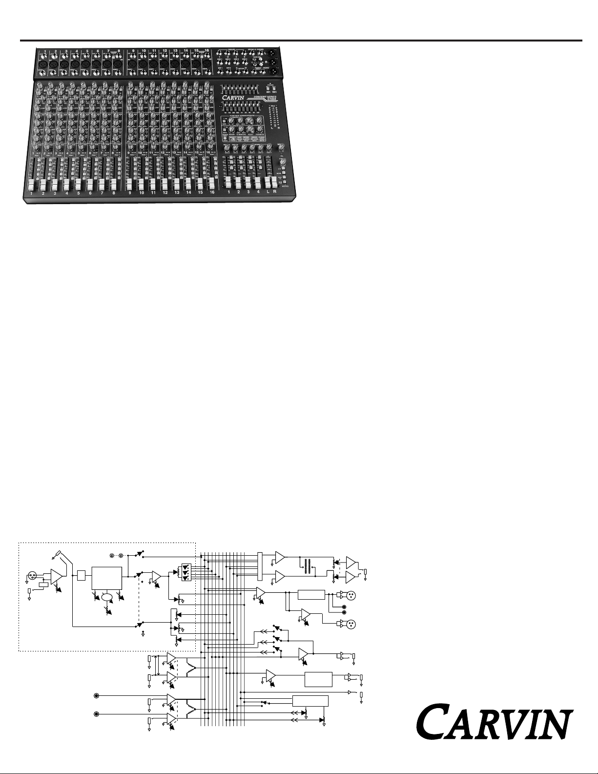
C1644 BLOCK DIAGRAM
C1644
CONCERT 44 SERIES Never before have so many features been packed into such a rugged, compact, American
made mixer. The best feature of the Concert 44 Series is the sound. Sound that is pure and quiet enough for
your digital recording studio! Everything is logically laid out making the powerful features simple to use and
the compact size makes it a breeze to carry. The knobs are not micro size, making adjustments quick and
easy - and the visible pointers show you the status of your mix at a glance. The C844, C1644, C2444 and
C3244 feature 8 to 32 channels with true 4-bus performance.
TRUE 4-BUS DESIGN The Concert 44 Series offers increased mixing flexibility over standard stereo
consoles by letting you assign channels to one of the 4 sub groups or L/R. This allows you to mix the
entire drum, horn, choir section, etc. into one sub group fader, which feeds the L/R faders. This is
an easy way to control the volume of grouped mics or inputs. If you don’t need subgrouping, you can
depress the L/R channel button and the channel goes directly into the L/R output like a standard stereo
console. All 4 sub group outputs have balanced outputs for long cable runs.
TWO EFFECT SENDS / TWO 24-BIT EFFECT PROCESSORS Two built-in 24-Bit effects, each offering
256 stereo effects, is a first in a 4-bus mixing console. Since there are two, you no longer have to
choose between that great vocal reverb with delay and that awesome guitar chorus - you can have
both! Each processor offers lush REVERBS, rich CHORUSES, thick textured FLANGING and pristine
ECHOES with fully adjustable parameters for damping, decay, depth, speed, time and regeneration.
Both processors can be sent back into the monitor mix so the performers can hear exactly what the
audience is hearing.
FOUR MONITOR SENDS Every channel can access any of the 4 MONITOR mixes while still having
access to 2 EFFECTS. The MONITOR 4-ALT EFF2 control not only sends to the MONITOR 4 output but
also sends to the EFFECTS 2 processor for two simultaneous effects per channel. All 4 monitor sends
are balanced.
3 BAND EQ/MID SWEEP The superb EQ system gives extended 15 dB boost and cut tone shaping. The
LOW frequency control builds bass response starting with 20 Hz through 80 Hz for a solid non-flabby
bass. The exclusive offset of the MID FREQ. control ends the confusion of selecting your mid frequency
from 100 Hz to 5kHz. The MID cut and boost control adjusts the gain to the perfect mid-dip or boost
curve to enhance all instruments and vocals. The 11.5k Hz HI treble control adds sparkle to your topend without adding harshness. Both the LOW and HI are “shelving”, which means they are effective
from 20 Hz and up to 20k Hz. The LO CUT switch eliminates stage rumble or other unwanted low frequencies that would normally rob power from your woofers.
TWO 9 BAND EQUALIZERS Precision equalizers provide precise 1 octave adjustments to tune in your
overall sound and control feedback. Unlike one stereo equalizer, two independent 9 bands offers total
flexibility. With two convenient buttons, you can assign either EQ to the R/L outputs or to the 1/2 monitor outputs. Center frequencies are 63, 125, 250, 500, 1k, 2k, 4k, 8k & 16k Hz.
RECEIVING INSPECTION—read before getting started
INSPECT YOUR MIXER FOR ANY DAMAGE which may have occurred during shipping. If any damage
is found, please notify the shipping company and CARVIN immediately.
SAVE THE CARTON & ALL PACKING MATERIALS. In the event you have to re-ship your unit, always
use the original carton and packing material. This will provide the best possible protection during
shipment. CARVIN and the shipping company are not liable for any damage caused by improper
packing.
SAVE YOUR INVOICE. It will be required for warranty service if needed in the future.
SHIPMENT SHORTAGE. If you find items missing, they may have been shipped separately. Please
allow several days for the rest of your order to arrive before inquiring.
RECORD THE SERIAL NUMBER on the enclosed warranty card or below on this manual for your
records. Keep your portion of the card and return the portion with your name and comments to us.
CHANNEL FEATURES Every channel has a full balanced XLR and LINE (1/4”) preamp with an
INSERT jack for a compressor or EQ that also serves as a DIRECT OUT when plugged half way.
The PAN control directs the channel into the L/R output or any of the 4 sub groups after depressing the appropriate ASSIGN switches. A PFL (pre fader listen) switch allows you to hear the
channel before the fader is turned up in the headphones. A solid “on” condition of the PEAK
led indicates that the MUTE switch has been activated which turns the channel off including all
monitor and effect sends. When flashing during use, the PEAK led also lets you know when to
adjust the channel’s GAIN control to prevent channel overloading. The SIGNAL led lets you know
that a signal is coming through the channel starting at –20 dBu. A silky smooth 60mm audio taper
FADER delivers professional fade-outs. The PHANTOM power switches provide power through
the XLR connectors for use with condenser mics like the Carvin CM90E in groups of 8 channels.
MASTER FEATURES Each of the 4 SUB GROUP faders can be switched to the R/L outputs or used
independently through their own balanced output jacks. Each of the sub group’s PFL switches
allow you to listen to the sub groups in your headphones before it is turned up. The R/L MAIN
output faders are independent for added flexibility over a single stereo fader. A MONO control
sums both the R/L outputs together for a center, side fill or subwoofer output. The stereo HEADPHONE control tracks the METER switches which allow you to look and listen from the L/R, MONO,
MONITOR 1/2 and 3/4 outputs and channel PFL switches. The master section also features 2
EFFECT SENDS, 4 RETURNS and RCA TAPE IN/OUT jacks. All 4 SUB GROUPS, 4 MONITORS,
XLR L/R and MONO outputs are balanced. A FOOT SWITCH jack turns both effects processors
on or off remotely with the optional FS22 foot switch.
SWITCHING POWER SUPPLY Our exclusive 125k Hz switching power supply eliminates transformer noise. Like a laptop computer, go anywhere in the world and not worry about power
because you can run on any voltage from 90 to 250VAC.
SUPERB SOUND State-of-the-art low impedance, low noise preamps are featured on every channel. The balanced common mode rejection is better than 70 dB to eliminate cable noise. All
main outputs are balanced to guard against system noise. The near theoretical limit on distortion has been achieved with THD below .01% to guarantee the purity of your sound, ensuring it
will be dynamically open and transparent.
ENGINEERED TO LAST Hidden deep in the heart of these USA made mixers is the SMT construction that utilizes surface mounted components to prevent malfunctions caused by vibrations. Sealed
controls and switches guard against the outside elements while heavy-duty jacks provide a positive connection to your cables. Fire retardant FR-4 military spec circuit cards feature double-sided
copper to eliminate radio frequency interference. Precision 1% tolerance components guarantee your settings will be accurate every time. The Concert 44 Series is built to strict standards.
For your records, you may wish to record the following information. Serial No._________________________ InvoiceDate___________
Optional Accessories:
C844: CB800 Heavy padded bag FS22 foot switch for all models
C1644: CB1600 Heavy padded bag AN1600 Anvil™ hard case
C2444: CB2400 Heavy padded bag AN2400 Anvil™ hard case
C3244:
AN3200 Anvil™ hard case
Page 3

C44 SERIES CONTROLS
CHANNEL FEATURES
1. 1/4” LINE INPUTS
The line connectors are for connecting balanced and unbalanced instruments and line level sources such as drum
machines, keyboards, ETC.
2. XLR MIC INPUTS
The balanced Mic inputs are for connecting microphones that
use XLR connections. Both the LINE and XLR MIC inputs can
be used simultaneously.
3. CHANNEL INSERT/CHANNEL DIRECT OUT
To insert channel effects, compressor, etc. use a 1/4” TRS (Tip
Ring Sleeve) cable (see INSERTS AND DIRECT OUT illustration
on page 5 for TRS details). To achieve a direct out from the channel, insert a standard 1/4” cable to the first “click” (1/2 insert).
4. GAIN
The GAIN controls the input level for the channel. If the GAIN
is set too high, the PEAK LED will flash and distortion may
occur. Decrease the amount of GAIN until the PEAK LED does
not flash. It is important that the gain control should be kept
right under the PEAK LED flash point to maintain the lowest
noise performance of the channel. You can use the channel
PFL switch to monitor the channel input level and use the
meters to adjust the GAIN control to 0dB. This will give you
a good reference point where the GAIN control should be set.
5. LOW CUT SWITCH
A 75 Hz LOW CUT filter helps eliminate unwanted low fre-
quencies. Great for reducing “boom” noise from mic stands
or from acoustic/electric guitars. Turning up the LOW EQ when
using this filter can help create a punchier bass response.
6. ACTIVE 3 BAND EQ
The C44 SERIES mixers provide studio EQ. The ±15 dB boost
or cut gives an overall 30 dB range for powerful EQ control.
The active circuits deliver deep bass from the 20-80 Hz LOW
control. The MID control works at 100Hz to 5kHz, depending on the MID FREQ control. The HI control functions at 1120k for crisp highs.
Start out with all tone controls at their center “zero” posi-
tion. Determine which position your MID FREQ sounds best,
then cut or boost your HI, MID, and LOW frequencies as
needed. If you are trying to mic instruments such as acoustic
guitar or drums, try various mics and mic placement before
adjusting your tone controls. A typical setting may be: HI +6,
MID -4 (MID FREQ set at 700Hz), and LOW +4. Don’t be afraid
to push the HI and LOW controls to get good presence and
depth while reducing the MID’s to clean up your sound. This
is the key to great sound.
7. MID SWEEP
This control allows you to select which frequency (from 100Hz
to 5kHz) that the MID control will boost or cut. Instruments
and singers have various tonal qualities. By adjusting the MID
FREQ, you can select the exact frequency that will best complement these various inputs. 700Hz is a recommended setting for the MID FREQ control for guitar and vocals.
8. 9. 10. MONITOR 1 THRU 4 CONTROLS
The channel MONITOR controls allow you to create four independent monitor mixes. The MONITOR signals (pre-EQ, pre
fader) are routed to the master MON 1, 2, 3 and 4 controls
(#24) respectively before going to the output connectors (#39).
To start, use MON 1. The MON 2/MON 3 control will send
either to MON 2 or MON 3. The center position is OFF. The
MON 4-ALT EFF 2 not only sends to the MON 4 out but also
to the EFF2 if the EFF2/MON 4 switch (#21) is selected in the
master EFFECTS 2 processor. This provides two simultaneous effects per channel and the use of MON 4.
11. EFF 1/EFF 2 CONTROL
The EFF 1/2 control will send a signal to EFFECTS 1 or
EFFECTS 2 and to the EFF 1-2 jacks (#36). The center posi-
tion is OFF. If BOTH effects are desired simultaneously for
all channels, press the MASTER EFFECTS 2 SOURCE
EFF2/MON4 switch (# 21) and use the MON 4 channel send,
which will also send to the MON 4 output (#39).
12. PAN CONTROL
Each channel’s PAN control allows stereo imaging by panning
Left or Right during recordings or live performances. The PAN
control also works for the sub-mix groups. A center position will send a channel’s signal to a pair of sub-group faders
(1-2, 3-4 when assigned). By panning hard left, the signal is
routed to only sub-group fader 1 or 3 when assigned. Panning
hard right routes the signal to sub-mix fader 2 or 4. Dual element pan controls provide 15dB greater separation than
standard pan controls.
13. CHANNEL SIGNAL GREEN LED
The SIGNAL LED is pre-fader and post EQ. This LED helps the
operator verify that the channel is receiving a signal from the
mic or instrument inputs even when the channel fader is off.
14. CHANNEL PEAK RED LED
This peak indicator is pre-fader and post EQ. If the PEAK LED
flashes, the channel needs a reduction with the GAIN control
(#4)to prevent distortion. A “solid” lit PEAK LED indicates that
the channel has been MUTED.
C844, C1644, C2444 & C3244 4-BUS MIXERS
QUICK START UP
If you’re like most new owners, you’re probably in a hurry
to plug your mixer in and use it. Here are some brief instructions to get you going quickly. With the mixer unplugged and
the unit turned off, complete the following procedures:
1. CONNECTING AC POWER TO YOUR MIXER
• The mixer can be used with 120 or 240VAC (it automatically switches internally)
• Use only a grounded (3 prong) power outlet to prevent a
shock hazard. This gives the quietest grounding for your mixer.
2. CONNECTING INPUTS TO YOUR MIXER
• For low level balanced devices such as microphones, plug
into the balanced MIC inputs using a shielded microphone
cable with XLR connectors.
• For high level balanced or unbalanced devices such as
instruments & keyboards, plug into the LINE input jacks using
a shielded cable with 1/4” phone plugs. Adjust the GAIN knob
for the mic or line input being used.
3. TURNING YOUR MIXER ON
• Adjust all channel FADERS and master LEVEL controls to
their OFF
positions
• Adjust all channel’s HI, MID, and BASS controls and the
two master 9 Band GRAPHICS to their center position.
• Adjust the Channel “PAN”controls to their center
position.
• Turn the mixer on by the rear panel POWER SWITCH
and watch for the POWER LED. Your mixer is now ready
to operate.
PHANTOM
CONCERT SERIES
LR
0
1-8
POWER
1
1
LINE
1
MIC
INSERT
MID
HI
C
LR
0
0
0
PAN
PEAK
SIG
010
5
010
5
2/3
MON
4
MON
EFF
1/2
1
MON
050
GAIN
LO
CUT
PFL
MUTE
3-4
1-2
L-R
OFF
MON
3MON 2
99
66
33
OFF
EFF 2EFF 1
99
66
33
LOW
FREQ
EFF
ALT
2
0
-12
-24
-30
-50
+
12
+
6
-6
100 5k
1k
+
15- 15
+
15- 15
+
15- 15
2
2
LINE
2
MIC
INSERT
MID
HI
C
LR
0
0
0
PAN
PEAK
SIG
010
5
010
5
2/3
MON
4
MON
EFF
1/2
1
MON
050
GAIN
LO
CUT
PFL
MUTE
3-4
1-2
L-R
OFF
MON
3MON 2
99
66
33
OFF
EFF 2EFF 1
99
66
33
LOW
FREQ
EFF
ALT
2
0
-12
-24
-30
-50
+
12
+
6
-6
100 5k
1k
+
15- 15
+
15- 15
+
15- 15
3
3
LINE
3
MIC
INSERT
MID
HI
C
LR
0
0
0
PAN
PEAK
SIG
010
5
010
5
2/3
MON
4
MON
EFF
1/2
1
MON
050
GAIN
LO
CUT
PFL
MUTE
3-4
1-2
L-R
OFF
MON
3MON 2
99
66
33
OFF
EFF 2EFF 1
99
66
33
LOW
FREQ
EFF
ALT
2
0
-12
-24
-30
-50
+
12
+
6
-6
100 5k
1k
+
15- 15
+
15- 15
+
15- 15
4
4
LINE
4
MIC
INSERT
MID
HI
C
LR
0
0
0
PAN
PEAK
SIG
010
5
010
5
2/3
MON
4
MON
EFF
1/2
1
MON
050
GAIN
LO
CUT
PFL
MUTE
3-4
1-2
L-R
OFF
MON
3MON 2
99
66
33
OFF
EFF 2EFF 1
99
66
33
LOW
FREQ
EFF
ALT
2
0
-12
-24
-30
-50
+
12
+
6
-6
100 5k
1k
+
15- 15
+
15- 15
+
15- 15
5
5
LINE
5
MIC
INSERT
MID
HI
C
LR
0
0
0
PAN
PEAK
SIG
010
5
010
5
2/3
MON
4
MON
EFF
1/2
1
MON
050
GAIN
LO
CUT
PFL
MUTE
3-4
1-2
L-R
OFF
MON
3MON 2
99
66
33
OFF
EFF 2EFF 1
99
66
33
LOW
FREQ
EFF
ALT
2
0
-12
-24
-30
-50
+
12
+
6
-6
100 5k
1k
+
15- 15
+
15- 15
+
15- 15
6
6
LINE
6
MIC
INSERT
MID
HI
C
LR
0
0
0
PAN
PEAK
SIG
010
5
010
5
2/3
MON
4
MON
EFF
1/2
1
MON
050
GAIN
LO
CUT
PFL
MUTE
3-4
1-2
L-R
OFF
MON
3MON 2
99
66
33
OFF
EFF 2EFF 1
99
66
33
LOW
FREQ
EFF
ALT
2
0
-12
-24
-30
-50
+
12
+
6
-6
100 5k
1k
+
15- 15
+
15- 15
+
15- 15
7
7
LINE
7
MIC
INSERT
MID
HI
C
LR
0
0
0
PAN
PEAK
SIG
010
5
010
5
2/3
MON
4
MON
EFF
1/2
1
MON
050
GAIN
LO
CUT
PFL
MUTE
3-4
1-2
L-R
OFF
MON
3MON 2
99
66
33
OFF
EFF 2EFF 1
99
66
33
LOW
FREQ
EFF
ALT
2
0
-12
-24
-30
-50
+
12
+
6
-6
100 5k
1k
+
15- 15
+
15- 15
+
15- 15
8
8
8
MIC
INSERT
MID
HI
C
LR
0
0
0
PAN
PEAK
SIG
010
5
010
5
2/3
MON
4
MON
EFF
1/2
1
MON
050
GAIN
LO
CUT
PFL
MUTE
3-4
1-2
L-R
OFF
MON
3MON 2
99
66
33
OFF
EFF 2EFF 1
99
66
33
LOW
FREQ
EFF
ALT
2
0
-12
-24
-30
-50
+
12
+
6
-6
100 5k
1k
+
15- 15
+
15- 15
+
15- 15
9
9
LINE
9
MIC
INSERT
MID
HI
C
LR
0
0
0
PAN
PEAK
SIG
010
5
010
5
2/3
MON
4
MON
EFF
1/2
1
MON
050
GAIN
LO
CUT
PFL
MUTE
3-4
1-2
L-R
OFF
MON
3MON 2
99
66
33
OFF
EFF 2EFF 1
99
66
33
LOW
FREQ
EFF
ALT
2
0
-12
-24
-30
-50
+
12
+
6
-6
100 5k
1k
+
15- 15
+
15- 15
+
15- 15
10
10
LINE
10
MIC
INSERT
MID
HI
C
LR
0
0
0
PAN
PEAK
SIG
010
5
010
5
2/3
MON
4
MON
EFF
1/2
1
MON
050
GAIN
LO
CUT
PFL
MUTE
3-4
1-2
L-R
OFF
MON
3MON 2
99
66
33
OFF
EFF 2EFF 1
99
66
33
LOW
FREQ
EFF
ALT
2
0
-12
-24
-30
-50
+
12
+
6
-6
100 5k
1k
+
15- 15
+
15- 15
+
15- 15
11
11
LINE
11
MIC
INSERT
MID
HI
C
LR
0
0
0
PAN
PEAK
SIG
010
5
010
5
2/3
MON
4
MON
EFF
1/2
1
MON
050
GAIN
LO
CUT
PFL
MUTE
3-4
1-2
L-R
OFF
MON
3MON 2
99
66
33
OFF
EFF 2EFF 1
99
66
33
LOW
FREQ
EFF
ALT
2
0
-12
-24
-30
-50
+
12
+
6
-6
100 5k
1k
+
15- 15
+
15- 15
+
15- 15
12
12
LINE
12
MIC
INSERT
MID
HI
C
LR
0
0
0
PAN
PEAK
SIG
010
5
010
5
2/3
MON
4
MON
EFF
1/2
1
MON
050
GAIN
LO
CUT
PFL
MUTE
3-4
1-2
L-R
OFF
MON
3MON 2
99
66
33
OFF
EFF 2EFF 1
99
66
33
LOW
FREQ
EFF
ALT
2
0
-12
-24
-30
-50
+
12
+
6
-6
100 5k
1k
+
15- 15
+
15- 15
+
15- 15
13
13
LINE
13
MIC
INSERT
C
LR
0
0
0
PEA
S
010
5
010
5
050
GAIN
OFF
MMON
2
9
6
3
OFF
EEFF 1
9
6
3
FREQ
0
-12
-24
-30
-50
+
12
+
6
-6
+
15- 15
+
15- 15
+
15- 15
1
19
2
3
4
5
7
6
8
9
10
11
12
13
14
15
16
18
17
6
2
Page 4

15. CHANNEL MUTE SWITCH
Use the MUTE switch to kill the channel. This feature saves
having to reset your faders and monitor sends.
16. CHANNEL PFL SWITCH
This switch allows the operator to listen to a channel (pre
fader listen) in the headphone mix to set tone and gain levels
as well as see the channel at the LED meter output (#32).
17. CHANNEL ASSIGNMENT SWITCHES
These switches assign the channels’ signal to the Master L/R
faders, or to the SUB-GROUP faders 1 & 2, 3 & 4 for submixing in stereo pairs. For mono, PAN fully to the left and
assign a channel to Sub-Group fader 1 or 3 only. PAN fully
to the right and assign a channel to Sub-Group fader 2 or
4. Likewise assigning the L/R switches sends the channel
directly to the main L or R faders.
18. CHANNEL FADER
The CHANNEL FADER adjusts the output level of the channel.
The signal will go to one or more of the Master Faders, depending on both the Channel Assignment switches and the PAN con-
trol. Calibrated 60mm FADERS with audio taper are featured
for smooth fade-outs. Slide all faders down when connecting your inputs. Note: for best board performance, channel
faders should be set slightly higher than the Sub-Groups and
Master L/R faders.
19. MIC PHANTOM POWER SWITCH / RED LED
This switch provides phantom power for condenser mics such
as Carvin’s CM90E in groups of 8 channels. This leaves the
remaining MIC inputs for sources that don’t require phantom
power. The LINE inputs are unaffected by phantom power.
MASTER SECTION
20. TWO STEREO 24-BIT EFFECTS
The internal 24-BIT stereo processors receive signals from
the EFF 1 / EFF 2 channel controls. If the adjacent PK (peak)
LED flashes, reduce the level from the channel EFF 1 / EFF
2 control. A “solid” PK LED will show EFFECTS 1 or 2 have
been muted, either by the MUTE switches or by the optional
FS22 footswitch (#41). The RETURN control will adjust the
volume level of the selected effects. Remember each channel
has its own EFFECT send that will send the signal to the effects
processors. The red PK LED will indicate when the effects signal
from the channel is distorting. Reduce the level of the channel EFFECT control until the PK LED stops flashing.
EFFECT AND PARAMETERS
ECHO: When the SELECT control is at the “7 O-clock” posi-
tion, it is selected to the first ECHO setting where you get a single
repeat echo (minimal regeneration). Turning the PARAMETER
control to 1 will provide the shortest delay time between the original
signal and the echo. Increasing the
PARAMETER control to the right
will increase the time delay between
the original signal and the echo. To
increase the number of echo repeats,
turn the SELECT control clockwise
to “9 O-clock” (maximum regeneration).
REVERB: When the SELECTcontrol
is at the “10 O-clock” position, it is
selected to the first REVERB setting.
Turning the SELECT control clockwise will increase the amount of high
frequencies in the reverb. Turning the
PARAMETER control to 1 will provide minimal decay time of the
reverb. Increasing to the right will
increase the reverb decay time.
CHORUS: When the SELECT control is at the “1 O-clock” position it
is selected to the first CHORUS set-
ting. Turning the SELECT control
clockwise will increase the amount
reverb in the chorus. Turning the
PARAMETER control to 1 will provide a minimal chorus depth setting.
Increasing to the right will increase
the chorus depth.
FLANGE: When the SELECTcontrol
is at the “4 O-clock” position it is
selected to the first FLANGE setting.
Turning the SELECT control clockwise will increase the flanger’s speed.
Turning the PARAMETER control to
1 will provide minimal flanging depth.
Increasing to the right will increase
the flanger’s depth.
To send effects to the monitors,
use the “TO MONITORS” controls,
MON 1/MON 2 & MON 1/MON 3.
The center position on both controls is OFF.
21. SOURCE EFF2/MON4 SWITCH
In the “OUT” position, the EFFECTS 2 processor gets its signal from
the EFF2channel send control. Clicking this switch “IN” will route
the MON 4 mix (#10) to the internal EFFECTS 2 processor. This
allows both effects to be used on each channel simultaneously.
22. RETURN 3 L/R
Receives stereo or 2 mono effect signals from the RETURN 3
L /R jacks. These signals will also be present at MON 1 (#39).
23. RCA TAPE IN/RTN EFF4 JACKS
Receives a signal from the RTN 4 L/R 1/4” jacks (#38) & from the
TAPE IN jacks (#44). These signals will also be present at MON 1.
24. MONITOR 1-4 CONTROLS
These are the master out-
puts for the four monitor sends. These correspond to the balanced 1/4” MON 1-4 output jacks
(#39)
.
25. GROUP/SUB-MIX FADERS 1-4
Once a channel has been assigned to one of these faders, the
mixing process is simplified to using these four faders. If
these faders are not assigned to the Master L-R faders (#27),
then each fader is bused to the corresponding 4 GROUP 1/4”
outputs (#40). By assigning the 4 faders to the Master L-R
faders, the operator can use the faders to sub-mix groups.
26. GROUP PFL SWITCHES
These
PFL
switches allow the operator to monitor the entire
GROUP mix. If
distortion is heard or if
the PFL level is near
PEAK
on the Master L/R METERS, lower the channel faders
assigned to that group. Also check the channel PEAK
LEDs.
27. GROUP ASSIGNMENT SWITCHES
These switches send the sub-group mix to the main L/R faders.
For mono mixing, assign to both L/R.
28. MASTER L/R FADERS
These faders adjust the level of the main stereo output created by
all channels and groups assigned to L/R faders. Output appears
at the L/R balanced XLR connectors
(#45)
.
29. MONO OUTPUT
The C44 SERIES creates an extra mono output from the
L/R
master faders (post) for center, side fill speakers or subwoofers.
The output is at the MONO XLR connector (#46).
30. HEADPHONE AND METER SOURCE
The stereo PHONES control sets the level of the PHONES jack
(#42). The PFL, L/R, MONO, MON 1-2 and MON 3-4 switches
allow for isolation of these sources through the headphones
and the L/R LED METERS (#32).
31. PFL RED LED
Indicates that the headphone & meters are monitoring only
the channels or groups where the PFL is switched on.
32. L/R LED VU METERS
This group of 10 LEDs offer 6 dB increment resolution that give
the operator a visual indication of the mixer’s output levels, selectable by the METER SOURCE or PFL switches
(#30).
33. DUAL PRECISION 9 BAND GRAPHIC EQs
are one octave filters at 60,125, 250, 500, 1k, 2k, 4k, 8k &
16k Hz centers that offer ±12dB adjustment to help eliminate feedback & enhance tone for the main or monitor mix.
34. EQ SWITCH 1 & 2
These switches swap the 9 band EQ’s from the standard L/R main
outputs “OUT” to the MON 1 & MON 2 outputs “IN” respectively.
35. POWER LED Verifies the mixer is on.
36. EFFECTS 1 & 2 OUTPUT JACKS
1/4” outputs drive external effects. Connect your effects
processor’s inputs to these jacks.
37. RETURN 3 L/R INPUT JACKS
Returns a stereo signal from an external effect. Connect your
effects processors’ stereo outputs to these jacks. If only one
RTN 3 jack is used, the mono signal will go to both L/R .
38. RTN 4 L/R INPUT JACKS
Returns a stereo signal from other sources.
39. MONITOR 1-4 OUTPUT JACKS
The C44 SERIES provides balanced 1/4” outputs for long cable
runs. Connect your monitor power amps to these jacks.
40. GROUP 1-4 OUTPUT JACKS
The C44 SERIES provides balanced 1/4” outputs. Connect your
4-track recorder or side fill power amps to these jacks.
41. EFF SW 1-2 FOOTSWITCH JACK
The optional FS22 will remotely shut off EFFECTS 1 or 2.
42. HEADPHONE JACK
1/4” stereo jack for headphone or control room output.
43. RCA L & R TAPE OUT
RCA jacks for connecting to a tape recorder input.
44. RCA L & R TAPE IN
For stereo playback of a tape/CD (parallel with RTN 4 jacks).
45. L/ R XLR OUTPUT CONNECTORS
This set of balanced XLR connectors are for connecting
the main L/R output to power amps or recording gear.
46. MONO XLR OUTPUT CONNECTOR
A balanced XLR output is featured for side fills or subwoofers.
1-2
3-4
MONO
L-R
EQ 1 EQ 2
00
0105010501050105010
5
RTN 3 MON 2MON 1 MON 4RTN 4 MON 3
TAPE INRETURN MONITORS
010
5
PK
PK
MONO
MUTE
MUTE
MON4
EFF2
SOURCE
LR
POWER
PFL
PHONES
LEFT /
MON 1
RIGHT /
MON 2
+18
+12
+6
0
- 6
-12
-18
-24
-30
PEAK
dB
CONCERT SERIES
C1644
010
5
OFF
99
66
33
1MON 2MON
OFF
99
66
33
1MON 3MON
-30
-50
-12
-24
12
6
-30
-50
-12
-24
12
6
-30
-50
-12
-24
12
6
-30
-50
+
-12
-24
12
010
5
LEFT
RIGHT
LEFT
RIGHT
LEFT
RIGHT
LEFT
RIGHT
24-BIT DUAL STEREO EFFECTS
125 250 50063 1K 2K 4K 8K 16K
0
8
4
4
8
±12
+12
0
8
4
4
8
12-
12+
PARAM
ECHO
REGEN
TIME
REVERB
DAMPING
DECAY
FLANGE
SPEED
DEPTH
CHORUS
REV LEVEL
DEPTH
SELECT
SELECT PARAMETER
101
2
3
4567
8
9
101
2
3
4567
8
9
EFFECTS 2
TO MONITORSRETURN
EFFECTS 1
0
8
4
4
8
±12
+12
0
8
4
4
8
12-
12+
L R
TAPE IN
1
L
TAPE OUT
R
MON 1
423
PHONES
EFF 1 3L 3R
RETURN
MONO
MON 2 MON 3
RTN 4
MON 4
EFF 2
GROUPS
100
1
2
3
456
7
8
9
100
1
2
3
4
5
6
7
8
9
METERS
1234LR
PFL PFL PFL PFL
0 0
MON
MON
EFF SW 1 2
-
0
-12
-24
-30
-50
+
12
+6
-6 -6-6 -6 -6
+6
PHANTOM
9-16
POWER
3
MID
HI
PAN
0
0
2/3
MON
4
MON
EFF
1/2
1
MON
LO
CUT
PFL
MUTE
3-4
1-2
L-R
3
9
6
3
9
6
3
LOW
EFF
ALT
2
100 5k
1k
14
14
LINE
14
MIC
INSERT
MID
HI
C
LR
0
0
0
PAN
PEAK
SIG
010
5
010
5
2/3
MON
4
MON
EFF
1/2
1
MON
050
GAIN
LO
CUT
PFL
MUTE
3-4
1-2
L-R
OFF
MON
3MON 2
99
66
33
OFF
EFF 2EFF 1
99
66
33
LOW
FREQ
EFF
ALT
2
0
-12
-24
-30
-50
+
12
+
6
-6
100 5k
1k
+
15- 15
+
15- 15
+
15- 15
15
15
LINE
15
MIC
INSERT
MID
HI
C
LR
0
0
0
PAN
PEAK
SIG
010
5
010
5
2/3
MON
4
MON
EFF
1/2
1
MON
050
GAIN
LO
CUT
PFL
MUTE
3-4
1-2
L-R
OFF
MON
3MON 2
99
66
33
OFF
EFF 2EFF 1
99
66
33
LOW
FREQ
EFF
ALT
2
0
-12
-24
-30
-50
+
12
+
6
-6
100 5k
1k
+
15- 15
+
15- 15
+
15- 15
16
16
16
MIC
INSERT
MID
HI
C
LR
0
0
0
PAN
PEAK
SIG
010
5
010
5
2/3
MON
4
MON
EFF
1/2
1
MON
050
GAIN
LO
CUT
PFL
MUTE
3-4
1-2
L-R
OFF
MON
3MON 2
99
66
33
OFF
EFF 2EFF 1
99
66
33
LOW
FREQ
EFF
ALT
2
0
-12
-24
-30
-50
+
12
+
6
-6
100 5k
1k
+
15- 15
+
15- 15
+
15- 15
39
40
20
32
33
33
35
36
37
38
46
45
21
24
29
31
27
30
22
25
26
28
23
43
41
42
44
3
Page 5

In a live sound reinforcement system, the input signals to the mixer will come from the microphones and instruments. Each microphone or instrument to be amplified by the system must be
connected to one of the mixing console inputs. It is preferred to have as many of the stage instruments as possible plugged into the mixer. This allows for the best overall control of the instruments as they are mixed together and then amplified by the system. The mixer can be operated
on the stage or from a remote location in the audience using a “snake cable” to bring the signals
from the stage to the mixer. The advantage of the remote operation allows the performance to be
mixed from the audience’s perspective. NOTE: Most snake cables are not designed for speaker
connections.
THE SOUND CHECK
The sound check takes some skill, but mostly patience from the performers and especially “you”
0 the system operator. If you get frustrated during the sound check, the sound may suffer due to
things missed in the sound check. The basic sound check follows this format: First test all micro-
phones and other input devices(direct boxes, etc.) before the performers are included in the sound
check. A good thing to also check here is feedback in the monitors from the microphones. Good
positioning of the monitors and the use of a graphic equalizer solves most major monitor feedback problems. Now for a sound check with the performers. First set the level of each performer
individually and in cases where a performer has multiple microphones such as with drummers,
set each drum mic individually then the drum set as a whole. This is also a good time to make
some channel EQ control adjustments to tailor the sound of the individual performers and instruments. After setting each individual, have the performers run through a song. Don’t hesitate to
stop the performers if something needs to be adjusted or a performer or microphone needs to
be heard solo again. Remember the sound check is not a rehearsal, but a system check. It is
always a good idea for the operator to have a microphone to inform the performers of what is
needed during the sound check. If a monitor system is being used, the operator’s microphone
should only be directed through the monitors when addressing the on stage performers, especially if something needs to be checked during the show.
PROTECT
∞
5050
3030
2222
1919
1717
1515
1313
1212
1111
1010
9
8
7
6
5
4
3
2
1
0 dB0 dB
DCM1000
1000 Watt Power Amp
CLIP
SIGNAL
∞
5050
30
2222
1919
1717
1515
1313
1212
1111
1010
9
8
7
6
5
4
3
2
1
0 dB0 dB
POWER
CHANNEL ONE CHANNEL TWO
CLIP
SIGNAL
PROTECT
∞
5050
3030
2222
1919
1717
1515
1313
1212
1111
1010
9
8
7
6
5
4
3
2
1
0 dB0 dB
DCM1000
1000 Watt Power Amp
CLIP
SIGNAL
∞
5050
3030
2222
1919
1717
1515
1313
1212
1111
1010
9
8
7
6
5
4
3
2
1
0 dB0 dB
POWER
CHANNEL ONE CHANNEL TWO
CLIP
SIGNAL
PROTECT
∞
5050
3030
2222
1919
1717
1515
1313
1212
1111
1010
9
8
7
6
5
4
3
2
1
0 dB0 dB
DCM1000
1000 Watt Power Amp
CLIP
SIGNAL
∞
5050
3030
2222
1919
1717
1515
1313
1212
1111
1010
9
8
7
6
5
4
3
2
1
0 dB0 dB
POWER
CHANNEL ONE CHANNEL TWO
CLIP
SIGNAL
PROTECT
∞
5050
3030
2222
1919
1717
1515
1313
1212
1111
1010
9
8
7
6
5
4
3
2
1
0 dB0 dB
DCM1000
1000 Watt Power Amp
CLIP
SIGNAL
∞
5050
3030
2222
1919
1717
1515
1313
1212
1111
1010
9
8
7
6
5
4
3
2
1
0 dB0 dB
POWER
CHANNEL ONE CHANNEL TWO
CLIP
SIGNAL
PHANTOM
1-2
3-4
MONO
L-R
EQ 1 EQ 2
00
0105010501050105010
5
RTN 3 MON 2MON 1 MON 4RTN 4 MON 3
TAPE INRETURN MONITORS
010
5
PK
PK
MONO
MUTE
MUTE
MON4
EFF2
SOURCE
LR
POWER
PFL
PHONES
LEFT /
MON 1
RIGHT /
MON 2
+18
+12
+6
0
- 6
-12
-18
-24
-30
PEAK
dB
CONCERCONCERT SERIEST SERIES
C1644
010
5
OFF
99
66
33
1MON 2MON
OFF
99
66
33
1MON 3MON
-30
-50
-12
-24
12
6
-30
-50
-12
-24
12
6
-30
-50
-12
-24
12
6
-30
-50
+
-12
-24
12
010
5
LEFT
RIGHT
LEFT
RIGHT
LEFT
RIGHT
LEFT
RIGHT
24-BIT DUAL STEREO EFFECTS
125 250 50063 1K 2K 4K 8K 16K
0
8
4
4
8
±12
+12
0
8
4
4
8
12-
12+
PARAM
ECHO
REGEN
TIME
REVERB
DAMPING
DECAY
FLANGE
SPEED
DEPTH
CHORUS
REV LEVEL
DEPTH
SELECT
SELECT PARAMETER
101
2
3
4567
8
9
101
2
3
4567
8
9
EFFECTS 2
TO MONITORSRETURN
EFFECTS 1
0
8
4
4
8
±12
+12
0
8
4
4
8
12-
12+
L R
TAPE IN
1
L
TAPE OUT
R
MON 1
423
PHONES
EFF 1 3L 3R
RETURN
MONO
MON 2 MON 3
RTN 4
MON 4
EFF 2
GROUPS
100
1
2
3
456
7
8
9
100
1
2
3
4
5
6
7
8
9
METERS
1234LR
PFL PFL PFL PFL
0 0
MON
MON
EFF SW 1 2
-
0
-12
-24
-30
-50
+
12
+6
-6 -6-6 -6 -6
+6
1-8
POWER
1
1
LINE
1
MIC
INSERT
MID
HI
C
LR
0
0
0
PAN
PEAK
SIG
010
5
010
5
2/3
MON
4
MON
EFF
1/2
1
MON
050
GAIN
LO
CUT
PFL
MUTE
3-4
1-2
L-R
OFF
MON
3MON 2
99
66
33
OFF
EFF
2EFF 1
99
66
33
LOW
FREQ
EFF
ALT
2
0
-12
-24
-30
-50
+
12
+
6
-6
100 5k
1k
+
15- 15
+
15- 15
+
15- 15
2
2
LINE
2
MIC
INSERT
MID
HI
C
LR
0
0
0
PAN
PEAK
SIG
010
5
010
5
2/3
MON
4
MON
EFF
1/2
1
MON
050
GAIN
LO
CUT
PFL
MUTE
3-4
1-2
L-R
OFF
MON
3MON 2
99
66
33
OFF
EFF
2EFF 1
99
66
33
LOW
FREQ
EFF
ALT
2
0
-12
-24
-30
-50
+
12
+
6
-6
100 5k
1k
+
15- 15
+
15- 15
+
15- 15
3
3
LINE
3
MIC
INSERT
MID
HI
C
LR
0
0
0
PAN
PEAK
SIG
010
5
010
5
2/3
MON
4
MON
EFF
1/2
1
MON
050
GAIN
LO
CUT
PFL
MUTE
3-4
1-2
L-R
OFF
MON
3MON 2
99
66
33
OFF
EFF
2EFF 1
99
66
33
LOW
FREQ
EFF
ALT
2
0
-12
-24
-30
-50
+
12
+
6
-6
100 5k
1k
+
15- 15
+
15- 15
+
15- 15
4
4
LINE
4
MIC
INSERT
MID
HI
C
LR
0
0
0
PAN
PEAK
SIG
010
5
010
5
2/3
MON
4
MON
EFF
1/2
1
MON
050
GAIN
LO
CUT
PFL
MUTE
3-4
1-2
L-R
OFF
MON
3MON 2
99
66
33
OFF
EFF
2EFF 1
99
66
33
LOW
FREQ
EFF
ALT
2
0
-12
-24
-30
-50
+
12
+
6
-6
100 5k
1k
+
15- 15
+
15- 15
+
15- 15
5
5
LINE
5
MIC
INSERT
MID
HI
C
LR
0
0
0
PAN
PEAK
SIG
010
5
010
5
2/3
MON
4
MON
EFF
1/2
1
MON
050
GAIN
LO
CUT
PFL
MUTE
3-4
1-2
L-R
OFF
MON
3MON 2
99
66
33
OFF
EFF
2EFF 1
99
66
33
LOW
FREQ
EFF
ALT
2
0
-12
-24
-30
-50
+
12
+
6
-6
100 5k
1k
+
15- 15
+
15- 15
+
15- 15
6
6
LINE
6
MIC
INSERT
MID
HI
C
LR
0
0
0
PAN
PEAK
SIG
010
5
010
5
2/3
MON
4
MON
EFF
1/2
1
MON
050
GAIN
LO
CUT
PFL
MUTE
3-4
1-2
L-R
OFF
MON
3MON 2
99
66
33
OFF
EFF
2EFF 1
99
66
33
LOW
FREQ
EFF
ALT
2
0
-12
-24
-30
-50
+
12
+
6
-6
100 5k
1k
+
15- 15
+
15- 15
+
15- 15
7
7
LINE
7
MIC
INSERT
MID
HI
C
LR
0
0
0
PAN
PEAK
SIG
010
5
010
5
2/3
MON
4
MON
EFF
1/2
1
MON
050
GAIN
LO
CUT
PFL
MUTE
3-4
1-2
L-R
OFF
MON
3MON 2
99
66
33
OFF
EFF
2EFF 1
99
66
33
LOW
FREQ
EFF
ALT
2
0
-12
-24
-30
-50
+
12
+
6
-6
100 5k
1k
+
15- 15
+
15- 15
+
15- 15
8
8
8
MIC
INSERT
MID
HI
C
LR
0
0
0
PAN
PEAK
SIG
010
5
010
5
2/3
MON
4
MON
EFF
1/2
1
MON
050
GAIN
LO
CUT
PFL
MUTE
3-4
1-2
L-R
OFF
MON
3MON 2
99
66
33
OFF
EFF
2EFF 1
99
66
33
LOW
FREQ
EFF
ALT
2
0
-12
-24
-30
-50
+
12
+
6
-6
100 5k
1k
+
15- 15
+
15- 15
+
15- 15
PHANTOM
9-16
POWER
9
9
LINE
9
MIC
INSERT
MID
HI
C
LR
0
0
0
PAN
PEAK
SIG
010
5
010
5
2/3
MON
4
MON
EFF
1/2
1
MON
050
GAIN
LO
CUT
PFL
MUTE
3-4
1-2
L-R
OFF
MON
3MON 2
99
66
33
OFF
EFF
2EFF 1
99
66
33
LOW
FREQ
EFF
ALT
2
0
-12
-24
-30
-50
+
12
+
6
-6
100 5k
1k
+
15- 15
+
15- 15
+
15- 15
10
10
LINE
10
MIC
INSERT
MID
HI
C
LR
0
0
0
PAN
PEAK
SIG
010
5
010
5
2/3
MON
4
MON
EFF
1/2
1
MON
050
GAIN
LO
CUT
PFL
MUTE
3-4
1-2
L-R
OFF
MON
3MON 2
99
66
33
OFF
EFF
2EFF 1
99
66
33
LOW
FREQ
EFF
ALT
2
0
-12
-24
-30
-50
+
12
+
6
-6
100 5k
1k
+
15- 15
+
15- 15
+
15- 15
11
11
LINE
11
MIC
INSERT
MID
HI
C
LR
0
0
0
PAN
PEAK
SIG
010
5
010
5
2/3
MON
4
MON
EFF
1/2
1
MON
050
GAIN
LO
CUT
PFL
MUTE
3-4
1-2
L-R
OFF
MON
3MON 2
99
66
33
OFF
EFF
2EFF 1
99
66
33
LOW
FREQ
EFF
ALT
2
0
-12
-24
-30
-50
+
12
+
6
-6
100 5k
1k
+
15- 15
+
15- 15
+
15- 15
12
12
LINE
12
MIC
INSERT
MID
HI
C
LR
0
0
0
PAN
PEAK
SIG
010
5
010
5
2/3
MON
4
MON
EFF
1/2
1
MON
050
GAIN
LO
CUT
PFL
MUTE
3-4
1-2
L-R
OFF
MON
3MON 2
99
66
33
OFF
EFF
2EFF 1
99
66
33
LOW
FREQ
EFF
ALT
2
0
-12
-24
-30
-50
+
12
+
6
-6
100 5k
1k
+
15- 15
+
15- 15
+
15- 15
13
13
LINE
13
MIC
INSERT
MID
HI
C
LR
0
0
0
PAN
PEAK
SIG
010
5
010
5
2/3
MON
4
MON
EFF
1/2
1
MON
050
GAIN
LO
CUT
PFL
MUTE
3-4
1-2
L-R
OFF
MON
3MON 2
99
66
33
OFF
EFF
2EFF 1
99
66
33
LOW
FREQ
EFF
ALT
2
0
-12
-24
-30
-50
+
12
+
6
-6
100 5k
1k
+
15- 15
+
15- 15
+
15- 15
14
14
LINE
14
MIC
INSERT
MID
HI
C
LR
0
0
0
PAN
PEAK
SIG
010
5
010
5
2/3
MON
4
MON
EFF
1/2
1
MON
050
GAIN
LO
CUT
PFL
MUTE
3-4
1-2
L-R
OFF
MON
3MON 2
99
66
33
OFF
EFF
2EFF 1
99
66
33
LOW
FREQ
EFF
ALT
2
0
-12
-24
-30
-50
+
12
+
6
-6
100 5k
1k
+
15- 15
+
15- 15
+
15- 15
15
15
LINE
15
MIC
INSERT
MID
HI
C
LR
0
0
0
PAN
PEAK
SIG
010
5
010
5
2/3
MON
4
MON
EFF
1/2
1
MON
050
GAIN
LO
CUT
PFL
MUTE
3-4
1-2
L-R
OFF
MON
3MON 2
99
66
33
OFF
EFF
2EFF 1
99
66
33
LOW
FREQ
EFF
ALT
2
0
-12
-24
-30
-50
+
12
+
6
-6
100 5k
1k
+
15- 15
+
15- 15
+
15- 15
16
16
16
MIC
INSERT
MID
HI
C
LR
0
0
0
PAN
PEAK
SIG
010
5
010
5
2/3
MON
4
MON
EFF
1/2
1
MON
050
GAIN
LO
CUT
PFL
MUTE
3-4
1-2
L-R
OFF
MON
3MON 2
99
66
33
OFF
EFF
2EFF 1
99
66
33
LOW
FREQ
EFF
ALT
2
0
-12
-24
-30
-50
+
12
+
6
-6
100 5k
1k
+
15- 15
+
15- 15
+
15- 15
E
C
H
O
R
E
V
E
R
B
C
H
O
R
U
S
F
L
A
N
G
E
R
E
C
H
O
R
E
V
E
R
B
C
H
O
R
U
S
F
L
A
N
G
E
R
10K
6K 45K
35K
25K
20
10 230
120
50
EQ IN
0
GAIN
PEAK
HI CUT
Hz
LOW CUT
Hz
-
OO
dB +6
31.5 4025 50 63
0dB
+6
+3
-3
-6
15
15
+
-
100 16012580 200 250 400 630500315
1k 1.25k800 1.6k 2k 3.15k 5k4k2.5k
6.3K 8K 12.5K 20K16K10K
10K
6K 45K
35K
25K
20
10 230
120
50
EQ IN
0
GAIN
PEAK
HI CUT
Hz
LOW CUT
Hz
-
OO
dB +6
31.5 4025 50 63
0dB
+6
+3
-3
-6
15
15
+
-
100 16012580 200 250 400 630500315
1k 1.25k800 1.6k 2k 3.15k 5k4k2.5k
6.3K 8K 12.5K 20K16K10K
ON
OFF
EQ2030
40 6325 100 160
0dB
+6
+3
-3
-6
15
15
+
-
400 1K630250 1.6K 2.5K 6.3K 16K10K4K
40 6325 100 160
0dB
+6
+3
-3
-6
15
15
+
-
400 1K630250 1.6K 2.5K 6.3K 16K10K4K
CHANNEL TWOCHANNEL ONE
ON
OFF
EQ2015
10K
6K 45K
35K
25K
20
10 230
120
50
EQ IN
0
GAIN
PEAK
HI CUT
Hz
LOW CUT
Hz
-
OO
dB +6
10K
6K 45K
35K
25K
20
10 230
120
50
EQ IN
0
GAIN
PEAK
HI CUT
Hz
LOW CUT
Hz
-
OO
dB +6
STEREO LIVE SOUND SYSTEM
CHANNEL CONNECTIONS AND SUB-MIXING
MASTER OUTPUTS
The main stereo loudspeakers should contain an overall mix
of all channels. The sub-group faders 1-4 can have certain channels assigned to them before the mix arrives at the master LR faders. This is known as sub-mixing and can improve the
efficiency of mixing a large number of channels (see above).
The four independent monitor mixes should use the MON 1
through MON 4 sends. On the channel these sends are pre-EQ,
pre-fader. The MONO output can be used for a main mono
mix, a center mix or as a subwoofer output.
The sub group outputs can also be used as side or back fill
speakers. Long rooms can have poor sound at the back of the
room. Set up a set of back fill loudspeakers to fill in and add
a digital delay to the main speakers to correct the time delay
from front to back. This can improve the sound of the room
considerably.
PHANTOM
1-2
3-4
MONO
L-R
EQ 1 EQ 2
00
0105010501050105010
5
RTN 3 MON 2MON 1 MON 4RTN 4 MON 3
TAPE INRETURN MONITORS
010
5
PK
PK
MONO
MUTE
MUTE
MON4
EFF2
SOURCE
LR
POWER
PFL
PHONES
LEFT /
MON 1
RIGHT /
MON 2
+18
+12
+6
0
- 6
-12
-18
-24
-30
PEAK
dB
CONCERCONCERT SERIEST SERIES
C1644
010
5
OFF
99
66
33
1MON 2MON
OFF
99
66
33
1MON 3MON
-30
-50
-12
-24
12
6
-30
-50
-12
-24
12
6
-30
-50
-12
-24
12
6
-30
-50
+
-12
-24
12
010
5
LEFT
RIGHT
LEFT
RIGHT
LEFT
RIGHT
LEFT
RIGHT
24-BIT DUAL STEREO EFFECTS
125 250 50063 1K 2K 4K 8K 16K
0
8
4
4
8
±12
+12
0
8
4
4
8
12-
12+
PARAM
ECHO
REGEN
TIME
REVERB
DAMPING
DECAY
FLANGE
SPEED
DEPTH
CHORUS
REV LEVEL
DEPTH
SELECT
SELECT PARAMETER
101
2
3
4567
8
9
101
2
3
4567
8
9
EFFECTS 2
TO MONITORSRETURN
EFFECTS 1
0
8
4
4
8
±12
+12
0
8
4
4
8
12-
12+
L R
TAPE IN
1
L
TAPE OUT
R
MON 1
423
PHONES
EFF 1 3L 3R
RETURN
MONO
MON 2 MON 3
RTN 4
MON 4
EFF 2
GROUPS
100
1
2
3
456
7
8
9
100
1
2
3
4
5
6
7
8
9
METERS
1234LR
PFL PFL PFL PFL
0 0
MON
MON
EFF SW 1 2
-
0
-12
-24
-30
-50
+
12
+6
-6 -6-6 -6 -6
+
6
1-8
POWER
1
1
LINE
1
MIC
INSERT
MID
HI
C
LR
0
0
0
PAN
PEAK
SIG
010
5
010
5
2/3
MON
4
MON
EFF
1/2
1
MON
050
GAIN
LO
CUT
PFL
MUTE
3-4
1-2
L-R
OFF
MON
3MON 2
99
66
33
OFF
EFF
2EFF 1
99
66
33
LOW
FREQ
EFF
ALT
2
0
-12
-24
-30
-50
+
12
+
6
-6
100 5k
1k
+
15- 15
+
15- 15
+
15- 15
2
2
LINE
2
MIC
INSERT
MID
HI
C
LR
0
0
0
PAN
PEAK
SIG
010
5
010
5
2/3
MON
4
MON
EFF
1/2
1
MON
050
GAIN
LO
CUT
PFL
MUTE
3-4
1-2
L-R
OFF
MON
3MON 2
99
66
33
OFF
EFF
2EFF 1
99
66
33
LOW
FREQ
EFF
ALT
2
0
-12
-24
-30
-50
+
12
+
6
-6
100 5k
1k
+
15- 15
+
15- 15
+
15- 15
3
3
LINE
3
MIC
INSERT
MID
HI
C
LR
0
0
0
PAN
PEAK
SIG
010
5
010
5
2/3
MON
4
MON
EFF
1/2
1
MON
050
GAIN
LO
CUT
PFL
MUTE
3-4
1-2
L-R
OFF
MON
3MON 2
99
66
33
OFF
EFF
2EFF 1
99
66
33
LOW
FREQ
EFF
ALT
2
0
-12
-24
-30
-50
+
12
+
6
-6
100 5k
1k
+
15- 15
+
15- 15
+
15- 15
4
4
LINE
4
MIC
INSERT
MID
HI
C
LR
0
0
0
PAN
PEAK
SIG
010
5
010
5
2/3
MON
4
MON
EFF
1/2
1
MON
050
GAIN
LO
CUT
PFL
MUTE
3-4
1-2
L-R
OFF
MON
3MON 2
99
66
33
OFF
EFF
2EFF 1
99
66
33
LOW
FREQ
EFF
ALT
2
0
-12
-24
-30
-50
+
12
+
6
-6
100 5k
1k
+
15- 15
+
15- 15
+
15- 15
5
5
LINE
5
MIC
INSERT
MID
HI
C
LR
0
0
0
PAN
PEAK
SIG
010
5
010
5
2/3
MON
4
MON
EFF
1/2
1
MON
050
GAIN
LO
CUT
PFL
MUTE
3-4
1-2
L-R
OFF
MON
3MON 2
99
66
33
OFF
EFF
2EFF 1
99
66
33
LOW
FREQ
EFF
ALT
2
0
-12
-24
-30
-50
+
12
+
6
-6
100 5k
1k
+
15- 15
+
15- 15
+
15- 15
6
6
LINE
6
MIC
INSERT
MID
HI
C
LR
0
0
0
PAN
PEAK
SIG
010
5
010
5
2/3
MON
4
MON
EFF
1/2
1
MON
050
GAIN
LO
CUT
PFL
MUTE
3-4
1-2
L-R
OFF
MON
3MON 2
99
66
33
OFF
EFF
2EFF 1
99
66
33
LOW
FREQ
EFF
ALT
2
0
-12
-24
-30
-50
+
12
+
6
-6
100 5k
1k
+
15- 15
+
15- 15
+
15- 15
7
7
LINE
7
MIC
INSERT
MID
HI
C
LR
0
0
0
PAN
PEAK
SIG
010
5
010
5
2/3
MON
4
MON
EFF
1/2
1
MON
050
GAIN
LO
CUT
PFL
MUTE
3-4
1-2
L-R
OFF
MON
3MON 2
99
66
33
OFF
EFF
2EFF 1
99
66
33
LOW
FREQ
EFF
ALT
2
0
-12
-24
-30
-50
+
12
+
6
-6
100 5k
1k
+
15- 15
+
15- 15
+
15- 15
8
8
8
MIC
INSERT
MID
HI
C
LR
0
0
0
PAN
PEAK
SIG
010
5
010
5
2/3
MON
4
MON
EFF
1/2
1
MON
050
GAIN
LO
CUT
PFL
MUTE
3-4
1-2
L-R
OFF
MON
3MON 2
99
66
33
OFF
EFF
2EFF 1
99
66
33
LOW
FREQ
EFF
ALT
2
0
-12
-24
-30
-50
+
12
+
6
-6
100 5k
1k
+
15- 15
+
15- 15
+
15- 15
PHANTOM
9-16
POWER
9
9
LINE
9
MIC
INSERT
MID
HI
C
LR
0
0
0
PAN
PEAK
SIG
010
5
010
5
2/3
MON
4
MON
EFF
1/2
1
MON
050
GAIN
LO
CUT
PFL
MUTE
3-4
1-2
L-R
OFF
MON
3MON 2
99
66
33
OFF
EFF
2EFF 1
99
66
33
LOW
FREQ
EFF
ALT
2
0
-12
-24
-30
-50
+
12
+
6
-6
100 5k
1k
+
15- 15
+
15- 15
+
15- 15
10
10
LINE
10
MIC
INSERT
MID
HI
C
LR
0
0
0
PAN
PEAK
SIG
010
5
010
5
2/3
MON
4
MON
EFF
1/2
1
MON
050
GAIN
LO
CUT
PFL
MUTE
3-4
1-2
L-R
OFF
MON
3MON 2
99
66
33
OFF
EFF
2EFF 1
99
66
33
LOW
FREQ
EFF
ALT
2
0
-12
-24
-30
-50
+
12
+
6
-6
100 5k
1k
+
15- 15
+
15- 15
+
15- 15
11
11
LINE
11
MIC
INSERT
MID
HI
C
LR
0
0
0
PAN
PEAK
SIG
010
5
010
5
2/3
MON
4
MON
EFF
1/2
1
MON
050
GAIN
LO
CUT
PFL
MUTE
3-4
1-2
L-R
OFF
MON
3MON 2
99
66
33
OFF
EFF
2EFF 1
99
66
33
LOW
FREQ
EFF
ALT
2
0
-12
-24
-30
-50
+
12
+
6
-6
100 5k
1k
+
15- 15
+
15- 15
+
15- 15
12
12
LINE
12
MIC
INSERT
MID
HI
C
LR
0
0
0
PAN
PEAK
SIG
010
5
010
5
2/3
MON
4
MON
EFF
1/2
1
MON
050
GAIN
LO
CUT
PFL
MUTE
3-4
1-2
L-R
OFF
MON
3MON 2
99
66
33
OFF
EFF
2EFF 1
99
66
33
LOW
FREQ
EFF
ALT
2
0
-12
-24
-30
-50
+
12
+
6
-6
100 5k
1k
+
15- 15
+
15- 15
+
15- 15
13
13
LINE
13
MIC
INSERT
MID
HI
C
LR
0
0
0
PAN
PEAK
SIG
010
5
010
5
2/3
MON
4
MON
EFF
1/2
1
MON
050
GAIN
LO
CUT
PFL
MUTE
3-4
1-2
L-R
OFF
MON
3MON 2
99
66
33
OFF
EFF
2EFF 1
99
66
33
LOW
FREQ
EFF
ALT
2
0
-12
-24
-30
-50
+
12
+
6
-6
100 5k
1k
+
15- 15
+
15- 15
+
15- 15
14
14
LINE
14
MIC
INSERT
MID
HI
C
LR
0
0
0
PAN
PEAK
SIG
010
5
010
5
2/3
MON
4
MON
EFF
1/2
1
MON
050
GAIN
LO
CUT
PFL
MUTE
3-4
1-2
L-R
OFF
MON
3MON 2
99
66
33
OFF
EFF
2EFF 1
99
66
33
LOW
FREQ
EFF
ALT
2
0
-12
-24
-30
-50
+
12
+
6
-6
100 5k
1k
+
15- 15
+
15- 15
+
15- 15
15
15
LINE
15
MIC
INSERT
MID
HI
C
LR
0
0
0
PAN
PEAK
SIG
010
5
010
5
2/3
MON
4
MON
EFF
1/2
1
MON
050
GAIN
LO
CUT
PFL
MUTE
3-4
1-2
L-R
OFF
MON
3MON 2
99
66
33
OFF
EFF
2EFF 1
99
66
33
LOW
FREQ
EFF
ALT
2
0
-12
-24
-30
-50
+
12
+
6
-6
100 5k
1k
+
15- 15
+
15- 15
+
15- 15
16
16
16
MIC
INSERT
MID
HI
C
LR
0
0
0
PAN
PEAK
SIG
010
5
010
5
2/3
MON
4
MON
EFF
1/2
1
MON
050
GAIN
LO
CUT
PFL
MUTE
3-4
1-2
L-R
OFF
MON
3MON 2
99
66
33
OFF
EFF
2EFF 1
99
66
33
LOW
FREQ
EFF
ALT
2
0
-12
-24
-30
-50
+
12
+
6
-6
100 5k
1k
+
15- 15
+
15- 15
+
15- 15
E
C
H
O
R
E
V
E
R
B
C
H
O
R
U
S
F
L
A
N
G
E
R
E
C
H
O
R
E
V
E
R
B
C
H
O
R
U
S
F
L
A
N
G
E
R
00
-30
-50
-12
-24
12
6
-30
-50
-12
-24
12
6
-30
-50
-12
-24
12
6
-30
-50
+
-12
-24
12
LEFT
RIGHT
LEFT
RIGHT
LEFT
RIGHT
LEFT
RIGHT
1234LR
PFL PFL PFL PFL
0 00
-12
-24
-30
-50
+
12
+6
-6 -6-6 -6 -6
+6
CONNECTING UP
The XLR Mic inputs are balanced low impedance inputs. Phantom power
for condenser mics is available in channel groups of eight. This enables
the user to group all mics that require phantom power together, leaving
the rest of the channels available for dynamic microphones or line inputs.
The XLR Mic inputs and balanced 1/4” Line inputs on each channel can
be used simultaneously, however the two signals will be controlled by the
single GAIN control. Adjust the level of the instruments to balance the
mix. For stereo instruments, such as keyboards or drum machines, use
two consecutive channels to connect the Left and Right outputs from the
instrument. Then use
the PAN controls on the
two channels to pan
hard left and right for a
stereo mix. If a pair of
individual channels are
not available, one of the
stereo returns in the
master section can be
used.
Whenever possible, try to group all related instruments or mics near each
other on the mixer. For example: put all drum mics on channels 1 through
8, guitars, bass and keyboards on 9 through 16, and vocals on 17 through
24. This will make mixing, channel assigning and sub-mixing easier to
manage.
SUB-MIXING
The 4 bus section on the C44 mixers can be used for main outputs, surround outputs, side fills, outputs to a multi-track recorder, etc. but the most
common use is for sub mixing. Sub grouping is the process of assigning
multiple channels to a pair of sub group faders in the master section. This
is usually done to decrease the number of faders needed to adjust a group
of channels. For example: a drum kit with 6 or more microphones mixed
in stereo can be assigned to a pair sub-mix faders. If the drums need to
be adjusted in the main mix, only group 2 faders need be adjusted instead
of 6 channel faders. The individual microphones all use different fader
settings, so it is important to get a balanced mix of the entire drum kit
during the sound check. The drum sub-group faders are then assigned
to the L-R main faders. If the drums are to be mixed mono, use the channel pan controls to pan the audio “hard left” and the audio will only be
assigned to sub- group fader 1 or 3. Panning “hard right” will bus the
audio to sub-mix faders 2 or 4. Always keep channel and sub group faders
higher than the master L-R faders. Using the L-R fader or sub group fader
to boost the level of a week channel signal can result in excess noise.
The diagram depicts a standard live sound system
1. Stereo EQ and power amp for the main speakers on the Left/Right outputs.
2. Stereo power amp for two monitor mixes on the MON 1 and MON 2 outputs.
3. Bridged power amp for a subwoofer on the MONO output.
4. Power amp for the use as side fill or back of room fill on the Group outputs.
5. Effects processor in the EFF2 send, EFF3 stereo return loop.
1
2
3
4
5
The illustration shows channels 1-4 assigned to sub-mix faders
1 & 2. The final L-R mix is created by assigning the sub-mix faders
to the L-R faders.
4
Page 6

HALF INSERT DIRECT OUT
The “half” insert connection creates a
send signal without breaking the channels
signal path. The insert in this mode is no
longer used as an insert but it becomes
what is called an “insert direct out”. An
insert direct out functions as a normal
direct out but the plug has to be half
inserted. If an insert is needed on the
same channel, special cabling is required
to perform both functions. The half
insertion connects the tip of the plug
being inserted to the ring of the jack. If
the jack is fully inserted to where the tip
of the plug connects to the tip of the jack,
the internal jack switch will open and the
channel’s signal path will be broken. The
connection will still function as a direct
out but the channel’s signal will stop at
the insert and not continue on to the rest
of the channel. The result of the half insert
is multiple outputs for use in multi-track
recording.
FULL INSERT
The insert jack is a Tip Ring Sleeve (TRS)
1/4” phone jack, where the tip is the send,
the ring is the return and the sleeve is
ground. When used as an insert point or
in full insert mode, the channel is opened
up to allow an external piece of equipment
to be inserted into the channels signal
path. The channel signal coming from the
microphone preamplifier will be forced to
go through the external equipment before
it can continue back through the channel
re-entering before the channel EQ controls.
Most external equipment is not set up for
the TRS plug directly so an adapter cable
is required. The adapter cable will have on
one end the TRS plug and two mono plugs
either male or female on the other end. The
two plugs each have the ground connected
to the sleeve, one has the return on its tip
and the other has the send on its tip. This
allows the send to be connected to the input
of the external equipment and the return
to its output completing the insert loop back
to the channel.
INSERTS AND DIRECT OUTS
CONCER
T SERIES
A multi-track recorder can be connected to the Channel Insert jacks (1/2 plugged).
This set up could be used with a live set up to record a live show.
PHANTOM
1-2
3-4
MONO
L-R
EQ 1 EQ 2
00
0105010501050105010
5
RTN 3 MON 2MON 1 MON 4RTN 4 MON 3
TAPE INRETURN MONITORS
010
5
PK
PK
MONO
MUTE
MUTE
MON4
EFF2
SOURCE
LR
POWER
PFL
PHONES
LEFT /
MON 1
RIGHT /
MON 2
+18
+12
+6
0
- 6
-12
-18
-24
-30
PEAK
dB
CONCERCONCERT SERIEST SERIES
C1644
010
5
OFF
99
66
33
1MON 2MON
OFF
99
66
33
1MON 3MON
-30
-50
-12
-24
12
6
-30
-50
-12
-24
12
6
-30
-50
-12
-24
12
6
-30
-50
+
-12
-24
12
010
5
LEFT
RIGHT
LEFT
RIGHT
LEFT
RIGHT
LEFT
RIGHT
24-BIT DUAL STEREO EFFECTS
125 250 50063 1K 2K 4K 8K 16K
0
8
4
4
8
±12
+12
0
8
4
4
8
12-
12+
PARAM
ECHO
REGEN
TIME
REVERB
DAMPING
DECAY
FLANGE
SPEED
DEPTH
CHORUS
REV LEVEL
DEPTH
SELECT
SELECT PARAMETER
101
2
3
4567
8
9
101
2
3
4567
8
9
EFFECTS 2
TO MONITORSRETURN
EFFECTS 1
0
8
4
4
8
±12
+12
0
8
4
4
8
12-
12+
L R
TAPE IN
1
L
TAPE OUT
R
MON 1
423
PHONES
EFF 1 3L 3R
RETURN
MONO
MON 2 MON 3
RTN 4
MON 4
EFF 2
GROUPS
100
1
2
3
456
7
8
9
100
1
2
3
4
5
6
7
8
9
METERS
1234LR
PFL PFL PFL PFL
0 0
MON
MON
EFF SW 1 2
-
0
-12
-24
-30
-50
+
12
+6
-6 -6-6 -6 -6
+6
1-8
POWER
1
1
LINE
1
MIC
INSERT
MID
HI
C
LR
0
0
0
PAN
PEAK
SIG
010
5
010
5
2/3
MON
4
MON
EFF
1/2
1
MON
050
GAIN
LO
CUT
PFL
MUTE
3-4
1-2
L-R
OFF
MON
3MON 2
99
66
33
OFF
EFF
2EFF 1
99
66
33
LOW
FREQ
EFF
ALT
2
0
-12
-24
-30
-50
+
12
+
6
-6
100 5k
1k
+
15- 15
+
15- 15
+
15- 15
2
2
LINE
2
MIC
INSERT
MID
HI
C
LR
0
0
0
PAN
PEAK
SIG
010
5
010
5
2/3
MON
4
MON
EFF
1/2
1
MON
050
GAIN
LO
CUT
PFL
MUTE
3-4
1-2
L-R
OFF
MON
3MON 2
99
66
33
OFF
EFF
2EFF 1
99
66
33
LOW
FREQ
EFF
ALT
2
0
-12
-24
-30
-50
+
12
+
6
-6
100 5k
1k
+
15- 15
+
15- 15
+
15- 15
3
3
LINE
3
MIC
INSERT
MID
HI
C
LR
0
0
0
PAN
PEAK
SIG
010
5
010
5
2/3
MON
4
MON
EFF
1/2
1
MON
050
GAIN
LO
CUT
PFL
MUTE
3-4
1-2
L-R
OFF
MON
3MON 2
99
66
33
OFF
EFF
2EFF 1
99
66
33
LOW
FREQ
EFF
ALT
2
0
-12
-24
-30
-50
+
12
+
6
-6
100 5k
1k
+
15- 15
+
15- 15
+
15- 15
4
4
LINE
4
MIC
INSERT
MID
HI
C
LR
0
0
0
PAN
PEAK
SIG
010
5
010
5
2/3
MON
4
MON
EFF
1/2
1
MON
050
GAIN
LO
CUT
PFL
MUTE
3-4
1-2
L-R
OFF
MON
3MON 2
99
66
33
OFF
EFF
2EFF 1
99
66
33
LOW
FREQ
EFF
ALT
2
0
-12
-24
-30
-50
+
12
+
6
-6
100 5k
1k
+
15- 15
+
15- 15
+
15- 15
5
5
LINE
5
MIC
INSERT
MID
HI
C
LR
0
0
0
PAN
PEAK
SIG
010
5
010
5
2/3
MON
4
MON
EFF
1/2
1
MON
050
GAIN
LO
CUT
PFL
MUTE
3-4
1-2
L-R
OFF
MON
3MON 2
99
66
33
OFF
EFF
2EFF 1
99
66
33
LOW
FREQ
EFF
ALT
2
0
-12
-24
-30
-50
+
12
+
6
-6
100 5k
1k
+
15- 15
+
15- 15
+
15- 15
6
6
LINE
6
MIC
INSERT
MID
HI
C
LR
0
0
0
PAN
PEAK
SIG
010
5
010
5
2/3
MON
4
MON
EFF
1/2
1
MON
050
GAIN
LO
CUT
PFL
MUTE
3-4
1-2
L-R
OFF
MON
3MON 2
99
66
33
OFF
EFF
2EFF 1
99
66
33
LOW
FREQ
EFF
ALT
2
0
-12
-24
-30
-50
+
12
+
6
-6
100 5k
1k
+
15- 15
+
15- 15
+
15- 15
7
7
LINE
7
MIC
INSERT
MID
HI
C
LR
0
0
0
PAN
PEAK
SIG
010
5
010
5
2/3
MON
4
MON
EFF
1/2
1
MON
050
GAIN
LO
CUT
PFL
MUTE
3-4
1-2
L-R
OFF
MON
3MON 2
99
66
33
OFF
EFF
2EFF 1
99
66
33
LOW
FREQ
EFF
ALT
2
0
-12
-24
-30
-50
+
12
+
6
-6
100 5k
1k
+
15- 15
+
15- 15
+
15- 15
8
8
8
MIC
INSERT
MID
HI
C
LR
0
0
0
PAN
PEAK
SIG
010
5
010
5
2/3
MON
4
MON
EFF
1/2
1
MON
050
GAIN
LO
CUT
PFL
MUTE
3-4
1-2
L-R
OFF
MON
3MON 2
99
66
33
OFF
EFF
2EFF 1
99
66
33
LOW
FREQ
EFF
ALT
2
0
-12
-24
-30
-50
+
12
+
6
-6
100 5k
1k
+
15- 15
+
15- 15
+
15- 15
PHANTOM
9-16
POWER
9
9
LINE
9
MIC
INSERT
MID
HI
C
LR
0
0
0
PAN
PEAK
SIG
010
5
010
5
2/3
MON
4
MON
EFF
1/2
1
MON
050
GAIN
LO
CUT
PFL
MUTE
3-4
1-2
L-R
OFF
MON
3MON 2
99
66
33
OFF
EFF
2EFF 1
99
66
33
LOW
FREQ
EFF
ALT
2
0
-12
-24
-30
-50
+
12
+
6
-6
100 5k
1k
+
15- 15
+
15- 15
+
15- 15
10
10
LINE
10
MIC
INSERT
MID
HI
C
LR
0
0
0
PAN
PEAK
SIG
010
5
010
5
2/3
MON
4
MON
EFF
1/2
1
MON
050
GAIN
LO
CUT
PFL
MUTE
3-4
1-2
L-R
OFF
MON
3MON 2
99
66
33
OFF
EFF
2EFF 1
99
66
33
LOW
FREQ
EFF
ALT
2
0
-12
-24
-30
-50
+
12
+
6
-6
100 5k
1k
+
15- 15
+
15- 15
+
15- 15
11
11
LINE
11
MIC
INSERT
MID
HI
C
LR
0
0
0
PAN
PEAK
SIG
010
5
010
5
2/3
MON
4
MON
EFF
1/2
1
MON
050
GAIN
LO
CUT
PFL
MUTE
3-4
1-2
L-R
OFF
MON
3MON 2
99
66
33
OFF
EFF
2EFF 1
99
66
33
LOW
FREQ
EFF
ALT
2
0
-12
-24
-30
-50
+
12
+
6
-6
100 5k
1k
+
15- 15
+
15- 15
+
15- 15
12
12
LINE
12
MIC
INSERT
MID
HI
C
LR
0
0
0
PAN
PEAK
SIG
010
5
010
5
2/3
MON
4
MON
EFF
1/2
1
MON
050
GAIN
LO
CUT
PFL
MUTE
3-4
1-2
L-R
OFF
MON
3MON 2
99
66
33
OFF
EFF
2EFF 1
99
66
33
LOW
FREQ
EFF
ALT
2
0
-12
-24
-30
-50
+
12
+
6
-6
100 5k
1k
+
15- 15
+
15- 15
+
15- 15
13
13
LINE
13
MIC
INSERT
MID
HI
C
LR
0
0
0
PAN
PEAK
SIG
010
5
010
5
2/3
MON
4
MON
EFF
1/2
1
MON
050
GAIN
LO
CUT
PFL
MUTE
3-4
1-2
L-R
OFF
MON
3MON 2
99
66
33
OFF
EFF
2EFF 1
99
66
33
LOW
FREQ
EFF
ALT
2
0
-12
-24
-30
-50
+
12
+
6
-6
100 5k
1k
+
15- 15
+
15- 15
+
15- 15
14
14
LINE
14
MIC
INSERT
MID
HI
C
LR
0
0
0
PAN
PEAK
SIG
010
5
010
5
2/3
MON
4
MON
EFF
1/2
1
MON
050
GAIN
LO
CUT
PFL
MUTE
3-4
1-2
L-R
OFF
MON
3MON 2
99
66
33
OFF
EFF
2EFF 1
99
66
33
LOW
FREQ
EFF
ALT
2
0
-12
-24
-30
-50
+
12
+
6
-6
100 5k
1k
+
15- 15
+
15- 15
+
15- 15
15
15
LINE
15
MIC
INSERT
MID
HI
C
LR
0
0
0
PAN
PEAK
SIG
010
5
010
5
2/3
MON
4
MON
EFF
1/2
1
MON
050
GAIN
LO
CUT
PFL
MUTE
3-4
1-2
L-R
OFF
MON
3MON 2
99
66
33
OFF
EFF
2EFF 1
99
66
33
LOW
FREQ
EFF
ALT
2
0
-12
-24
-30
-50
+
12
+
6
-6
100 5k
1k
+
15- 15
+
15- 15
+
15- 15
16
16
16
MIC
INSERT
MID
HI
C
LR
0
0
0
PAN
PEAK
SIG
010
5
010
5
2/3
MON
4
MON
EFF
1/2
1
MON
050
GAIN
LO
CUT
PFL
MUTE
3-4
1-2
L-R
OFF
MON
3MON 2
99
66
33
OFF
EFF
2EFF 1
99
66
33
LOW
FREQ
EFF
ALT
2
0
-12
-24
-30
-50
+
12
+
6
-6
100 5k
1k
+
15- 15
+
15- 15
+
15- 15
E
C
H
O
R
E
V
E
R
B
C
H
O
R
U
S
F
L
A
N
G
E
R
E
C
H
O
R
E
V
E
R
B
C
H
O
R
U
S
F
L
A
N
G
E
R
MULTI-TRACK RECORDING
Follow this set up for mixing down to a two track recorder.
Connect the Multi-track recorders’ outputs to the line inputs
of the channels. Use the headphones or connect a professional power amplifier (Carvin’s DCM power amps) and high
quality studio monitors (Carvin’s SRS6.5) to your main L/R
outputs to monitor your mixdown sessions. Mixing is a practiced skill. A trained ear will know when to add EQ, effects,
compression, gate. Listen to your favorite CD through the
same headphones or monitoring system you plan to mix
through. Note each instrument’s level and position in the
stereo mix. Use this as a guide to help mix your project.
MULTI-TRACK MIXDOWN
5
ADJUSTING THE 9-BAND EQ
When the 9 band graphic EQ sliders are in their “center” position, they do not affect the
audio signal. When the EQ sliders are raised or lowered from this position, they boost
or cut respectively a narrow band of frequencies. To reduce feedback in the low frequency
range try lowering one of the 63, 125 or 250 Hz sliders. High frequency feedback is reduced
by lowering one of the 2k or 4k Hz sliders. To help with feedback reduction, the main speaker
should always be placed in front of the microphones.
For tone enhancement, you may want to raise the 63, 125 (for deeper bass) and the 4, 8
and 16k (for crisper highs). At the same time you may want to reduce the mid frequency at
1k forming a “smile” curve as shown.
LINE
MIC
GAIN
HI
MID
LOW
INSERT
5
4
3
2
1
010
- 0 +
3
6
9129
12
- 0 +
3
6
9
12
- 0 +
3
6
9
12
1
6
3
3
12
3
12
FULL INSERT
MIC Pre-Amp
PIN 2 (+)
PIN 3 (–)
GAIN
7
8
9
6
6
9
6
9
SEND RETURN
TO EFFECTS
TIP: SEND
RING: RETURN
SLEEVE: GROUND
INSERT JACK
STEREO PLUG
LINE
MIC
GAIN
HI
MID
LOW
INSERT
4
3
2
1
010
- 0 +
3
6
9129
12
- 0 +
3
6
9
12
- 0 +
3
6
9
12
1/2 INSERT
1
PIN 2 (+)
PIN 3 (–)
5
6
7
8
9
3
6
3
6
9
12
3
6
9
12
MIC Pre-Amp
GAIN
TO RECORDER
TIP: SIGNAL
SLEEVE: GROUND
INSERT JACK
MONO PLUG
GRAPHIC EQ
1
2
3
4
5
6
7
8
9
10
11
12
13
PHANTOM
LINE
LINE
LINE
+
125 25063
12
500 1K
8
4
0
4
8
12
-
4K 16K8K2K
+
12
8
4
0
4
8
12
-
LINE
MIC
MIC
MIC
MIC
INSERT
INSERT
INSERT
INSERT
LO
LO
LO
CUT
CUT
CUT
050
050
050
GAIN
GAIN
GAIN
0
0
0
HI
HI
HI
+
+
+
15- 15
15- 15
15- 15
1k
1k
1k
FREQ
FREQ
FREQ
0
0
0
1005k
1005k
1005k
MID
MID
MID
+
+
+
15- 15
15- 15
15- 15
0
0
0
LOW
LOW
LOW
+
+
+
15- 15
15- 15
15- 15
5
5
5
MON
MON
MON
1
1
1
010
010
010
MON
MON
MON
OFF
OFF
OFF
2/3
2/3
2/3
33
33
33
66
66
66
99
99
99
MON
MON
MON
3MON 2
3MON 2
3MON 2
5
MON
5
MON
5
MON
4
4
4
ALT
ALT
ALT
EFF
EFF
EFF
2
2
2
010
010
010
EFF
EFF
EFF
OFF
OFF
OFF
1/2
1/2
1/2
33
33
33
66
66
66
99
99
99
2EFF 1
2EFF 1
2EFF 1
EFF
EFF
EFF
PAN
PAN
PAN
C
C
C
LR
LR
LR
SIG
SIG
SIG
1
2
3
4
PEAK
PEAK
PEAK
12
12
12
12
+
+
+
+
MUTE
MUTE
MUTE
PFL
PFL
PFL
+
+
+
+
6
6
6
6
0
0
0
0
1-2
1-2
1-2
-6
-6
-6
-6
3-4
3-4
3-4
-12
-12
-12
-12
L-R
L-R
L-R
-24
-24
-24
-24
-30
-30
-30
-30
-50
-50
-50
-50
1
2
3
POWER
LINE
LINE
LINE
LINE
LINE
1-8
MIC
MIC
MIC
MIC
MIC
INSERT
INSERT
LO
LO
CUT
CUT
CUT
050
050
050
GAIN
GAIN
GAIN
0
0
0
HI
HI
HI
+
+
+
15- 15
15- 15
15- 15
1k
1k
FREQ
FREQ
FREQ
0
0
0
1005k
1005k
1005k
MID
MID
MID
+
+
+
15- 15
15- 15
15- 15
0
0
0
LOW
LOW
LOW
+
+
+
15- 15
15- 15
15- 15
5
5
5
MON
MON
MON
1
1
010
010
010
MON
MON
MON
OFF
OFF
OFF
2/3
2/3
2/3
33
33
33
66
66
66
99
99
99
MON
MON
MON
3MON 2
3MON 2
5
MON
5
MON
5
MON
4
4
ALT
ALT
EFF
EFF
2
2
010
010
010
EFF
EFF
EFF
OFF
OFF
OFF
1/2
1/2
1/2
33
33
33
66
66
66
99
99
99
2EFF 1
2EFF 1
EFF
EFF
EFF
PAN
PAN
PAN
C
C
C
LR
LR
LR
SIG
SIG
SIG
5
6
PEAK
PEAK
PEAK
12
12
+
+
MUTE
MUTE
MUTE
PFL
PFL
PFL
+
+
6
6
0
0
1-2
1-2
-6
-6
3-4
3-4
-12
-12
L-R
L-R
L-R
-24
-24
-30
-30
-50
-50
4
5
6
MIC
INSERT
INSERT
INSERT
INSERT
LO
LO
LO
LO
CUT
CUT
CUT
050
050
050
050
GAIN
GAIN
GAIN
GAIN
0
0
0
0
HI
HI
HI
+
+
+
+
15- 15
15- 15
15- 15
1k
1
3MON 2
4
ALT
EFF
2
2EFF 1
+
+
1-2
-6
3-4
-12
-24
-30
-50
15- 15
1k
1k
1k
FREQ
FREQ
FREQ
FREQ
0
0
0
0
1005k
1005k
1005k
MID
MID
MID
+
+
+
+
15- 15
15- 15
15- 15
15- 15
0
0
0
0
LOW
LOW
LOW
LOW
+
+
+
+
15- 15
15- 15
15- 15
15- 15
5
5
5
5
MON
MON
MON
1
1
1
010
010
010
010
MON
MON
MON
OFF
OFF
OFF
OFF
2/3
2/3
2/3
33
33
33
33
66
66
66
99
99
99
MON
MON
MON
MON
3MON 2
3MON 2
3MON 2
5
MON
5
MON
5
MON
5
4
4
4
ALT
ALT
ALT
EFF
EFF
EFF
2
2
2
010
010
010
010
EFF
EFF
EFF
OFF
OFF
OFF
OFF
1/2
1/2
1/2
33
33
33
33
66
66
66
99
99
99
2EFF 1
2EFF 1
2EFF 1
EFF
EFF
EFF
EFF
PAN
PAN
PAN
C
C
C
C
LR
LR
LR
LR
SIG
SIG
SIG
7
12
6
0
SIG
8
9
10
PEAK
PEAK
PEAK
PEAK
12
12
12
+
+
+
MUTE
MUTE
MUTE
PFL
PFL
PFL
+
+
+
6
6
6
0
0
0
1-2
1-2
1-2
-6
-6
-6
3-4
3-4
3-4
-12
-12
-12
L-R
L-R
L-R
-24
-24
-24
-30
-30
-30
-50
-50
-50
7
8
9
10
14
LINE
LINE
LINE
LINE
MIC
MIC
MIC
MIC
INSERT
INSERT
INSERT
INSERT
LO
LO
LO
LO
CUT
HI
1k
1005k
MID
MON
1
MON
2/3
66
99
3MON 2
MON
4
ALT
EFF
2
EFF
1/2
66
99
2EFF 1
PAN
MUTE
PFL
1-2
3-4
L-R
LO
CUT
CUT
CUT
CUT
050
050
050
050
GAIN
GAIN
GAIN
GAIN
0
0
0
0
HI
HI
HI
HI
+
+
+
+
15- 15
15- 15
15- 15
15- 15
1k
1k
1k
1k
FREQ
FREQ
FREQ
FREQ
0
0
0
0
1005k
1005k
1005k
1005k
MID
MID
MID
MID
+
+
+
+
15- 15
15- 15
15- 15
15- 15
0
0
0
0
LOW
LOW
LOW
LOW
+
+
+
+
15- 15
15- 15
15- 15
15- 15
5
5
5
5
MON
MON
MON
MON
1
1
1
1
010
010
010
010
MON
MON
MON
MON
OFF
OFF
OFF
OFF
2/3
2/3
2/3
2/3
33
33
33
33
66
66
66
66
99
99
99
99
MON
MON
MON
MON
3MON 2
3MON 2
3MON 2
3MON 2
5
MON
5
MON
5
MON
5
MON
4
4
4
4
ALT
ALT
ALT
ALT
EFF
EFF
EFF
EFF
2
2
2
2
010
010
010
010
EFF
EFF
EFF
EFF
OFF
OFF
OFF
OFF
1/2
1/2
1/2
1/2
33
33
33
33
66
66
66
66
99
99
99
99
2EFF 1
2EFF 1
2EFF 1
2EFF 1
EFF
EFF
EFF
EFF
PAN
PAN
PAN
PAN
C
C
C
C
LR
LR
LR
LR
SIG
SIG
SIG
SIG
11
12
13
14
PEAK
PEAK
PEAK
PEAK
12
12
12
12
+
+
+
+
MUTE
MUTE
MUTE
MUTE
PFL
PFL
PFL
PFL
+
+
+
+
6
6
6
6
0
0
0
0
1-2
1-2
1-2
1-2
-6
-6
-6
-6
3-4
3-4
3-4
3-4
-12
-12
-12
-12
L-R
L-R
L-R
L-R
-24
-24
-24
-24
-30
-30
-30
-30
-50
-50
-50
-50
11
12
13
14
15
PHANTOM
POWER
LINE
9-16
MIC
INSERT
INSERT
LO
CUT
050
GAIN
0
HI
+
15- 15
1k
FREQ
0
1005k
MID
+
15- 15
0
LOW
+
15- 15
5
MON
1
010
MON
OFF
2/3
33
66
99
MON
3MON 2
5
MON
4
ALT
EFF
2
010
EFF
OFF
1/2
33
66
99
2EFF 1
EFF
PAN
C
LR
SIG
15
PEAK
12
12
+
+
MUTE
PFL
+
+
6
6
0
0
1-2
-6
-6
3-4
-12
-12
L-R
-24
-24
-30
-30
-50
-50
15
16
1
MIC
MON 1
MON 2 MON 3
EFF 2
EFF 1 3L 3R
+12
LO
8
CUT
050
4
GAIN
0
0
4
8
HI
±12
+
15- 15
1k
FREQ
0
1005k
+12
MID
8
+
15- 15
4
0
0
LOW
4
8
±12
+
15- 15
125 250 50063 1K 2K 4K 8K 16K
5
MON
1
24-BIT DUAL STEREO EFFECTS
010
PK
4
3
MON
OFF
2/3
33
2
66
1
MUTE
99
MON
3MON 2
PK
456
5
MON
3
4
2
ALT
1
EFF
MUTE
2
010
SOURCE
EFF
OFF
EFF2
1/2
33
SELECT
66
99
MON4
PARAM
2EFF 1
EFF
PAN
C
5
LR
010
SIG
16
RTN 3 MON 2MON 1 MON 4RTN 4 MON 3
PEAK
LEFT
12
+
MUTE
RIGHT
PFL
+6
0
1-2
PFL PFL PFL PFL
-6 -6-6 -6 -6
3-4
-12
-12
L-R
-24
-24
-30
-30
-50
-50
1234LR
16
GROUPS
TAPE OUT
423
MON 4
L R
RETURN
CONCER
EFFECTS 1
E
R
C
E
OFF
5
H
G
6
33
O
N
4567
7
A
L
66
F
3
8
R
E
99
2
S
V
9
E
U
R
R
1MON 2MON
100
B
O
H
C
EFFECTS 2
E
R
C
E
OFF
H
G
33
O
N
4567
7
A
66
L
3
F
8
R
E
99
2
9
S
V
E
U
1MON 3MON
R
R
100
B
O
H
C
SELECT PARAMETER
TO MONITORSRETURN
ECHO
REVERB
FLANGE
CHORUS
REGEN
DAMPING
SPEED
REV LEVEL
TIME
DECAY
DEPTH
DEPTH
TAPE INRETURN MONITORS
0105010501050105010
LEFT
LEFT
LEFT
12
12
12
RIGHT
RIGHT
RIGHT
6
6
6
00
0 0
-12
-12
-24
-24
-30
-30
-50
-50
L
R
TAPE IN
MONO
RTN 4
POWER
12+
8
EQ 1 EQ 2
4
0
4
LEFT /
RIGHT /
8
MON 1
MON 2
12-
T SERIES
C1644
12+
8
4
PEAK
0
4
+18
8
12-
+12
+6
0
- 6
-12
-18
8
9
-24
101
-30
dB
LR
8
9
101
MONO
5
5
010
PFL
12
+
PHONES
5
+6
010
L-R
-12
MONO
-24
MON
-30
1-2
MON
-50
3-4
METERS
PHONES
EFF SW 1 2
 Loading...